Integrating automation and robotics has revolutionized modern industrial processes, particularly material handling. The EasyPLC Machine Simulator Robot Loader, which loads boxes onto skids in manufacturing facilities, can be used to help learn PLC programming.
This 3D simulation robot loader communicates with a Click PLC through Modbus TCP (Ethernet) communication, enabling seamless coordination and control. The Click PLC utilizes a Drum instruction to execute sequence control, ensuring optimal performance and precision.
To ensure a successful implementation of the EasyPLC Robot Loader, we will follow the five essential steps for PLC program development. This comprehensive approach will guide you in creating a seamless operation that maximizes efficiency and productivity.
So, let’s dive in and explore the exciting possibilities of how to program the EasyPLC Robot Loader!
Learn PLC programming the easy way. See below for a 10% discount on this cost-effective learning tool. Invest in yourself today.
Previously we have done the following:
Easy PLC Installing the Software – Video
EasyPLC Software Suite – Quick Start – Video
Click PLC – Easy Transfer Line Programming – Video
Productivity PLC Simulator – Chain Conveyor MS – Video
Do-More PLC – EasyPLC Box Selection Program – Video
Click PLC EasyPLC Gantry Simulator – Video
Click PLC Simple Conveyor EasyPLC – Video
EasyPLC Paint Line Bit Shift – BRX Do-More PLC – Video
Click PLC – EasyPLC PLC Mixer Programming – Video
Click PLC EasyPLC Warehouse Stacker Example – Video
– Operation Video
EasyPLC Machine Simulator Productivity PLC Robotic Cell – Video
EasyPLC Simulator Robotic Cell Click PLC – Video
EasyPLC Simulator Robotic Cell BRX Do-More PLC – Video
– EasyPLC Factory Editor Robotic Cell Additions Video
4 Way Traffic Light PLC Program EasyPLC – Video
Rock Crusher Plant EasyPLC BRX Do-More – Video
Freight Carrier Weighing and Distribution EasyPLC – Video
EasyPLC Machining Center Loading Robots – Video
EasyPLC Palletizing Robot Programming Click PLC – Video
EasyPLC Machine Editor – Design a Simulation – Video
PLC Programming Mixing Tank – EasyPLC / Do-More – Video
EasyPLC Solder Robot PLC Programming – Video
PLC Programming – A Tutorial for Beginners – Video
Automated Parking Demo Video
Parking Cars Simulator PLC Programming Part 1 – Video
Parking Cars Simulator PLC Programming Part 2 – Video
PLC Programming with Pneumatic Synchronization – Video
The Ultimate Guide to PLC Programming for Sorting Operations – Video
Optimizing Batch Processing with PLC Systems – Video
PLC Multi Conveyor Feed Control Demystified! – Video
Define the task: (Step 1 – EasyPLC Robot Loading – Click PLC)
The initial phase of developing a PLC program involves defining the task and determining the necessary steps to accomplish it. The EasyPLC software suite offers a variety of machine simulators, including a robot loading example, to aid in the learning and developing of PLC programming skills.
To access the EasyPLC Machine Simulator (MS), navigate to the main page and select the “start” button or choose “machines” from the top menu within the simulator window. With this powerful tool at your disposal, you can confidently tackle any PLC programming challenge that comes your way.
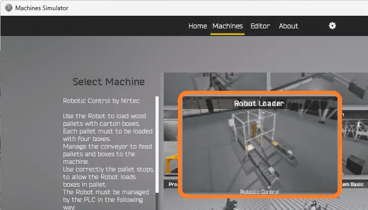
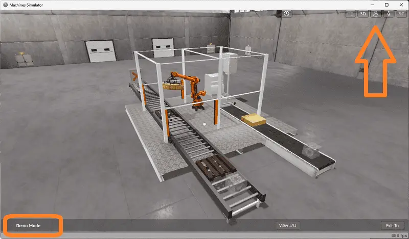
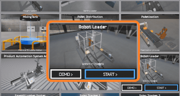
All the available machines will now be displayed. Click on the “Robot Loader.”
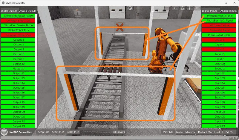
This is the example that we will be programming. To the left of the screen, information will be displayed on how this process needs to function.
Use the robot to load wood pallets with carton boxes. Each pallet must be loaded with four boxes. Manage the conveyors to feed pallets and boxes to the machine. Use the pallet stops to allow the robot to load boxes on the pallet correctly.
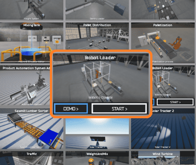
The machine simulator has a demo mode for the built-in machines. This will allow you to watch the operation of the robot loader machine. Select the demo mode.
The EasyPLC demo mode on the machine simulator will operate, showing you the basics of operation.
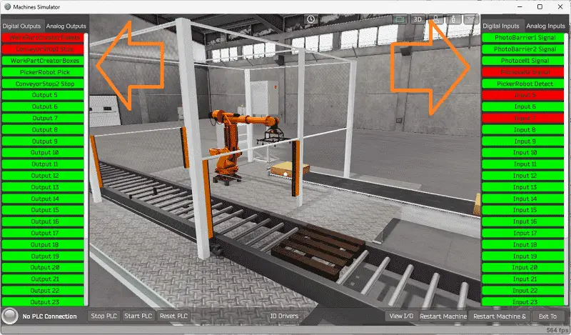
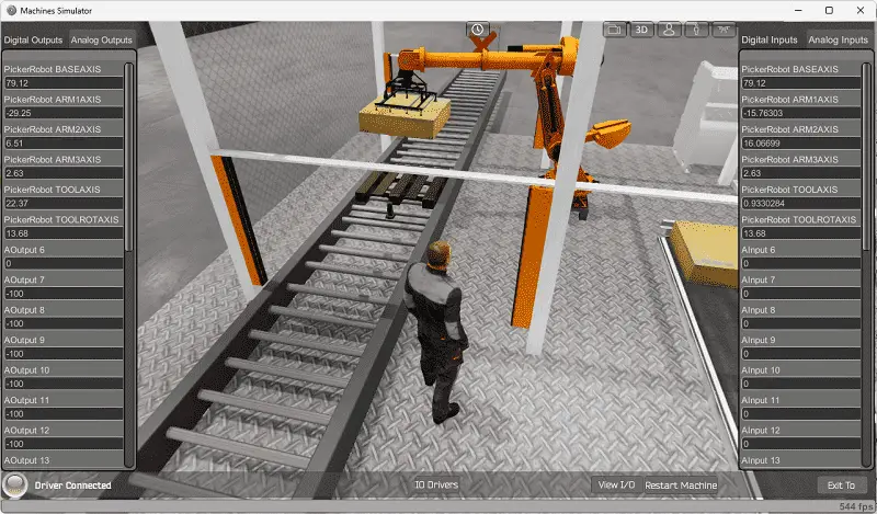
Move around the 3D virtual environment. The icons on the top of the window will allow you to move around this 3D environment.
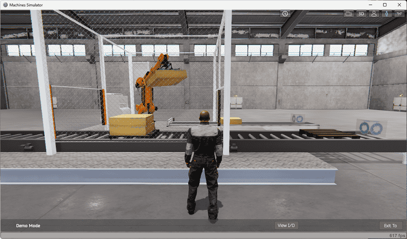
The first icon is the default selection. This will enable you to move around without bumping into the components. The first-person mode will mimic a person in your 3D learning world. The third person is used to show the operator’s relationship to the machine. The last icon will automatically show you around this virtual environment. Once we understand what must be done, we can move on to the next step in our PLC program development.
Define the Inputs and Outputs: (Step 2 – EasyPLC Robot Loading – Click PLC)
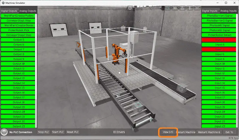
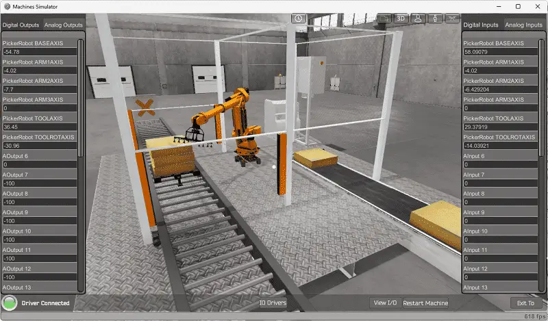
The View IO at the bottom of the machine simulator window will display the inputs and outputs required for this robot loader example. While still in demo mode, you can see the operation of the inputs and outputs.
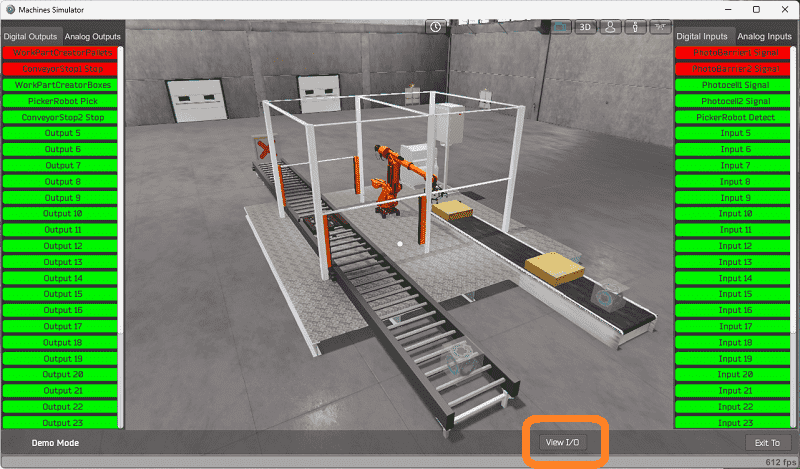
The EasyPLC robot loader example will require five digital outputs and five digital inputs. Select the analog inputs and outputs.
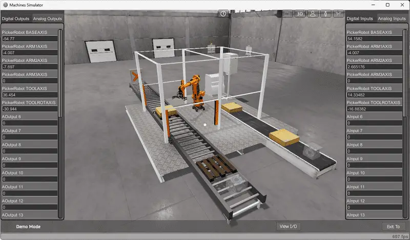
Six analog outputs will control the robot’s position, and six analog inputs will indicate the robot’s current position (feedback). Make a note of each of the positions that we will require for the robot movement.
The EasyPLC start mode will allow you to control this robot loader manually. Exit the demo mode and enter the start mode for this machine.
This is ideal if you need clarification on what output or input is doing.
Select the View IO on the bottom middle of the machine simulator window. You can manually run the machine simulator without any control or PLC connection.
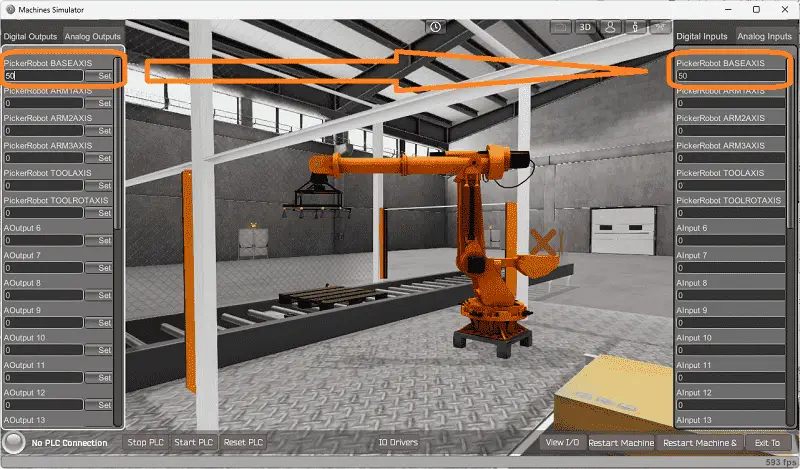
You can now select the robot loader feed digital outputs on the left side of the screen by clicking on them with the mouse. The right side will show you the corresponding digital inputs. Select the analog input and outputs. Change the values to ensure you know how the robot and feedback positions work.
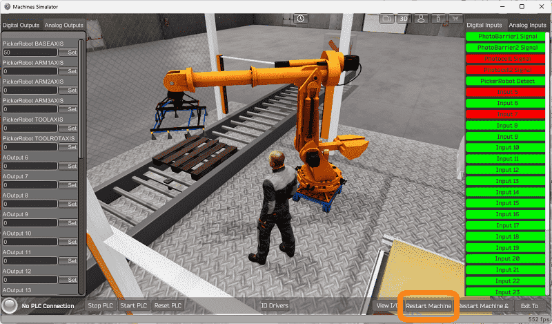
The restart button on the bottom of the machine simulator window will reset the scene back to the start.
Move around the 3D environment and ensure you know what each input and output represents.
The following table will define the inputs and outputs (IO) and Modbus addresses in the Click PLC we will use for this program.
| Digital Type | Description | Click PLC Modbus Address | Machine Simulator Modbus Address |
| PLC Output – MS Input | Work Part Creator Pallets | C101 – 16485 | 16484 |
| PLC Output – MS Input | Conveyor Stop 1 | C102 – 16486 | 16485 |
| PLC Output – MS Input | Work Part Creator Boxes | C103 – 16487 | 16486 |
| PLC Output – MS Input | Picker Robot Pick | C104 – 16488 | 16487 |
| PLC Output – MS Input | Conveyor Stop 2 | C105 – 16489 | 16488 |
| PLC Input – MS Output | Photo Barrier 1 Signal | C201 – 16585 | 16584 |
| PLC Input – MS Output | Photo Barrier 2 Signal | C202 – 16586 | 16585 |
| PLC Input – MS Output | Photocell 1 Signal | C203 – 16587 | 16586 |
| PLC Input – MS Output | Photocell 2 Signal | C204 – 16588 | 16587 |
| PLC Input – MS Output | Picker Robot Detect | C205 – 16589 | 16588 |
| PLC Analog Output – MS Analog Input | Robot Base Axis | DS1 – 400001 | 0 |
| PLC Analog Output – MS Analog Input | Robot Arm 1 Axis | DS2 – 400002 | 1 |
| PLC Analog Output – MS Analog Input | Robot Arm 2 Axis | DS3 – 400003 | 2 |
| PLC Analog Output – MS Analog Input | Robot Arm 3 Axis | DS4 – 400004 | 3 |
| PLC Analog Output – MS Analog Input | Robot Tool Axis | DS5 – 400005 | 4 |
| PLC Analog Output – MS Analog Input | Robot Tool Rotate Axis | DS6 – 400006 | 5 |
| PLC Analog Input – MS Analog Output | Robot Base Axis Feedback | DS101 – 400101 | 100 |
| PLC Analog Input – MS Analog Output | Robot Arm 1-Axis Feedback | DS102 – 400102 | 101 |
| PLC Analog Input – MS Analog Output | Robot Arm 2-Axis Feedback | DS103 – 400103 | 102 |
| PLC Analog Input – MS Analog Output | Robot Arm 3-Axis Feedback | DS104 – 400104 | 103 |
| PLC Analog Input – MS Analog Output | Robot Tool Axis Feedback | DS105 – 400105 | 104 |
| PLC Analog Input – MS Analog Output | PRobot Tool Rotate Axis Feedback | DS106 – 400107 | 105 |
Note: The machine simulator will be offset by one on the Modbus Addresses. See the video below for the demo mode and determining inputs and outputs.
Develop a logical sequence of operation: (Step 3 – EasyPLC Robot Loading – Click PLC)
A PLC programmer must know everything about the sequence and operation of the machine before programming. The sorting operation simulator is an excellent way to learn to program. Flow charts or sequence tables can be used to understand the process that needs to be controlled thoroughly. It must also answer questions like the following:
What happens when electrical power or pneumatic air is lost? What happens when the input/output devices fail? Do we need redundancy?
This step is where you will spend most of your time. Understanding everything about the operation will save you time. It will help prevent you from continuously re-writing the PLC program logic. Knowing all these answers to how the system reacts is vital in developing the PLC program. This does not have to be a formal document. You must have a method to account for every condition in the machine being programmed.
The robot loader has two conveyors. The belt conveyor will contain the boxes. It will operate when there is not a photocell 2 signal.
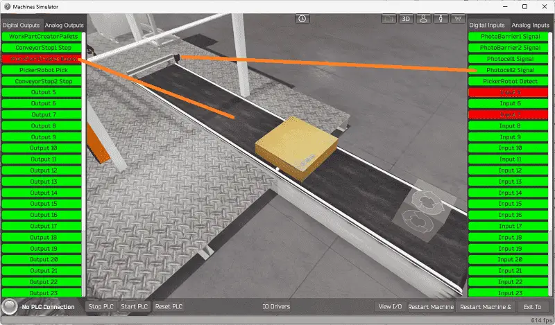
When the conveyor is on, it will automatically create another box. Photocell 2 will stop the conveyor from operating. The boxes will always be made while the robot loader is running.
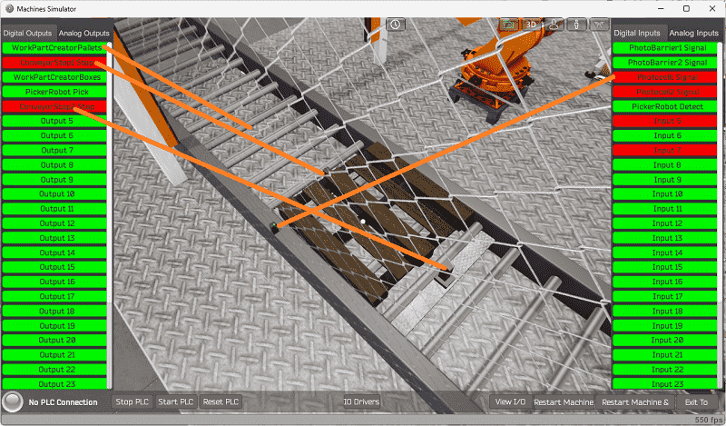
The roller conveyor contains the pallets. When it is running, new pallets are created automatically. Conveyor stopper 1 will activate to position the pallet to accept boxes. Stopper 2 is used to prevent other pallets into the stacking location.
If photocell 1 is not seen, stopper one will be activated, and the roller conveyor will turn on. When the photocell sees the pallet, the conveyor will stop, and stopper 2 will activate.
Once the pallet has 4 boxes, stopper 1 will deactivate, and the roller conveyor will start. This will allow the full pallet to exit the machine. Stopper 2 then deactivates and enables the next pallet to be loaded.
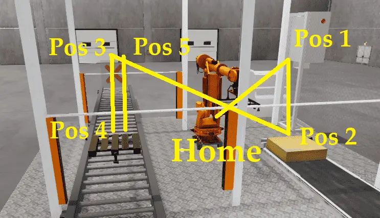
Our machine has a robot that will have 5 positions for each box that is loaded onto the pallet. It will also have a home position that will be used after a full pallet is complete.
Position 1 is above the box on the belt conveyor. Position 2 is when the box will get picked up by the robot. Position 3 is the location above the pallet.
Position 4 will be the robot’s location for each of the four boxes. The final fifth position is the same as position 3 above the pallet.
The robot loader also has two light curtains. These are located at the entrance and exit of the pallet roller conveyor. If the light curtain is tripped while the robot is moving, this will stop all movement.
The system will then need to be reset to start the operation again.
A PLC programmer must know how everything about the sequence and operation of the machine before programming.
Ensuring you know what must happen will help clarify what is required in the PLC program. Ask questions or view existing documentation to ensure you understand the logical steps to the machine’s operation. This may involve speaking with the manufacturer, operators, engineers, etc. Create your sequence of operations based on the information above.
Develop the Click PLC program: (Step 4 – EasyPLC Robot Loading – Click PLC)
Using the information from the previous steps, we can now program our Click PLUS PLC. The Click PLC Series will take you through installing the program, communicating with the controller, providing instructions, and addressing the controller.
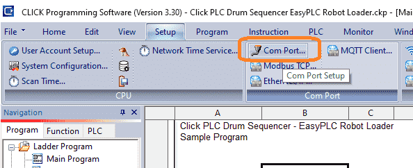
Select Com Port… in the Setup tab on the main menu.
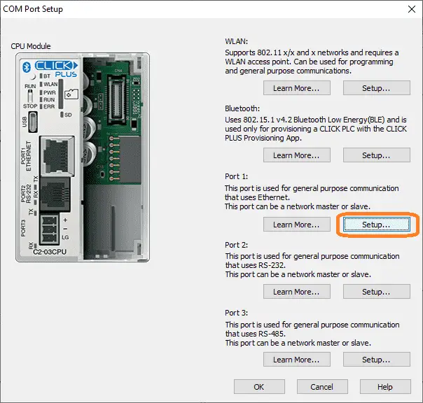
The COM Port Setup window will allow you to select the different port setups on your Click PLC. Select setup under Port 1.
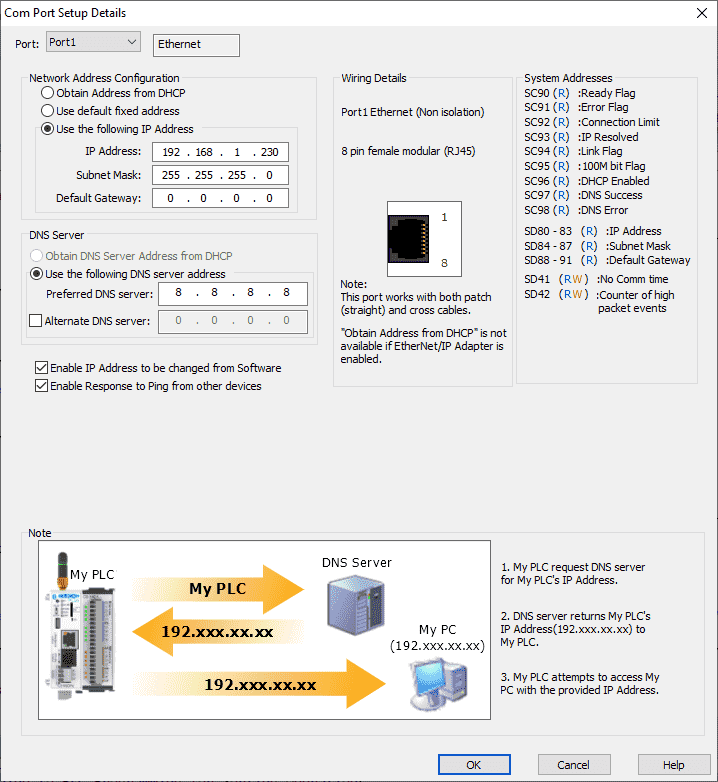
The Com Port Setup Details window will now be displayed. Alternatively, you can access this window by selecting Com Port1 Setup under the Function tab in the navigation menu. We have manually set up the Ethernet port with an IP address for our network.
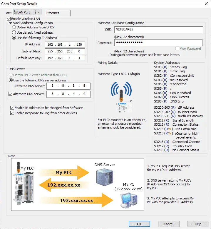
Select the WLAN Port. This is also set up manually for our network using Wi-Fi.
Our PLC is a Modbus TCP Server to the EasyPLC Modbus TCP Client. Please note these static IP addresses we use for the Click PLC. This will be used later to connect to the EasyPLC machine simulator.
We can now look at the ladder logic program of our Click PLC for our robot loader machine. This will also explain the logic as we look at the program.
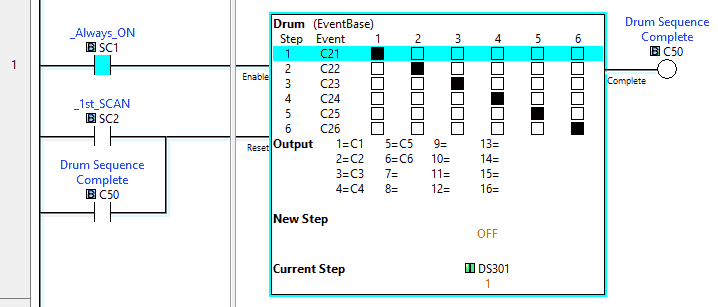
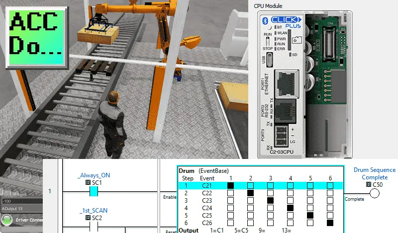
The drum instruction in the click has 6 steps and 6 outputs. Event input bits will determine the end of the step and continue with the next step. Outputs C1 to C6 will determine the sequence step that we are currently running.
C1 – Load Pallet
C2 – Robot to load box 1 onto a pallet
C3 – Robot to load box 2 onto a pallet
C4 – Robot to load box 3 onto a pallet
C5 – Robot to load box 4 onto a pallet
C6 – Exit Full Pallet

This rung will control boxes. If Photocell 2 is not on, activate the belt conveyor to get another box.
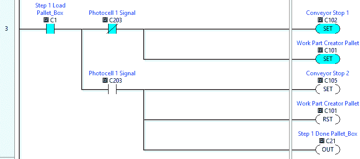
Step 1 load pallet will set the conveyor stop 1 and start the roller conveyor to bring in a pallet. When the pallet is seen by photocell 1, set conveyor stop 2, and reset the roller conveyor. C21 is the event to indicate that step 1 is complete and move to step 2 in the drum sequence.
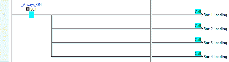
The next run will call up the loading subroutine for each of the 4 boxes to load on the conveyor.
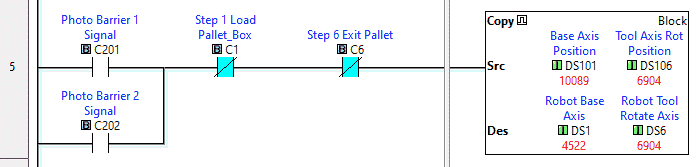
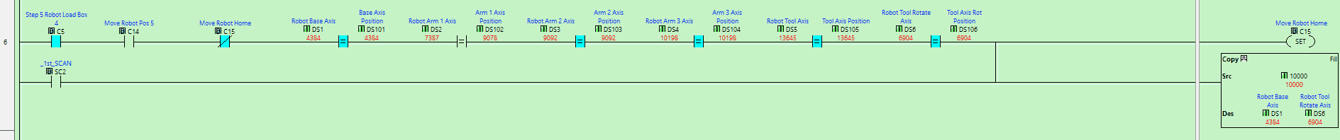
If we are on step 1 or step 6, move the robot’s current position into the robot’s set position. This will stop all movement of the robot. This will also happen if the photo barrier (safety curtain) is triggered at the entrance or exit of the roller conveyor.
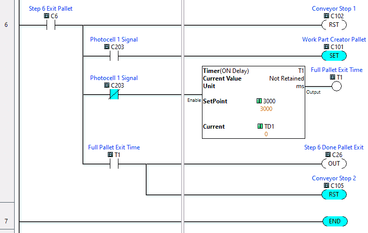
Rung 6 of the main ladder logic will control step 6 of the drum sequence. When step 6 is triggered, the conveyor stop 1 will reset, and the roller conveyor will start removing the full pallet of boxes. A timer ensures that the pallet is out of the machine. Then the conveyor stop 2 will reset, and then signal for the end of the step is activated.
This is the end of the main program.
The subroutine logic is all similar except for box 4 loading. This will add an extra step to the robot to home before moving to step 6 and exiting the full pallet.
Step 2 – Load Box 1 onto the Pallet
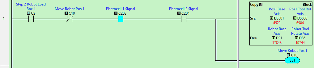
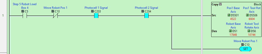
Once we enter step 2 and the pallet and box are in position, we will set the robot coordinates for position 1. We then set a bit to indicate that this step has been executed. (C10)
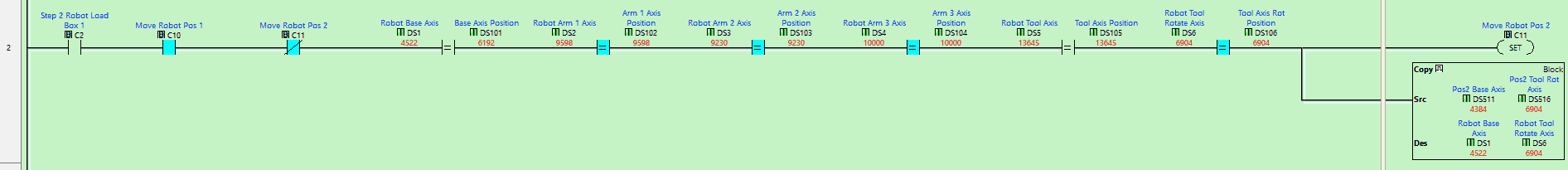
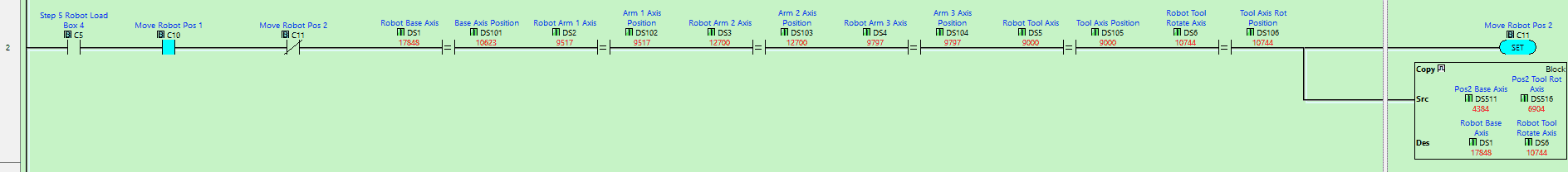
When in step 2 and the robot has been set for position 1, compare the 6 axes of the current position to the set positions. If they are the same, set position 2 for the robot and set a bit (C11) that indicates the robot’s movement.
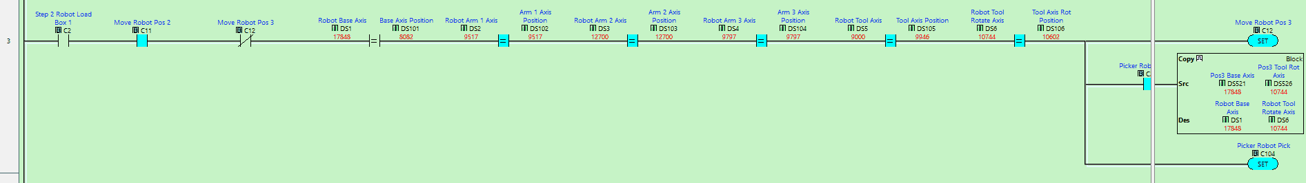
When in step 2 and the robot has been set for position 2, compare the 6 axes of the current position to the set positions. If they are the same, set the robot picker, set position 3 and set a bit (C12) that indicates the robot moves to position 3.
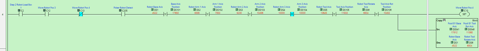
When in step 2 and the robot has been set for position 3, compare the 6 axes of the current position to the set positions. If they are the same, then set the robot for position 4 and set a bit (C13) that indicates the robot’s movement to position 4.
Note: Position 4 will have different coordinates for each box.
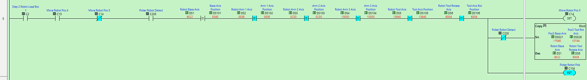
When in step 2 and the robot has been set for position 4, compare the 6 axes of the current position to the set positions. If they are the same, then set the robot for position 5, reset the robot picker and set a bit (C14) that indicates the robot’s moves to position 5.
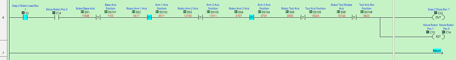
When in step 2 and the robot has been set for position 5, compare the 6 axes of the current position to the set positions. If they are the same, reset the robot position bits C10 to C14 and turn on the step done bit.
The program will then repeat steps 3 and step 4 for boxes 2 and 3. Logically these are identical.
Step 5 – Load Box 4 onto the Pallet
Once we enter step 5 and the pallet and box are in position, we will set the robot coordinates for position 1. We then set a bit to indicate that this step has been executed. (C10)
When in step 5 and the robot has been set for position 1, compare the 6 axes of the current position to the set positions. If they are the same, set position 2 for the robot and set a bit (C11) that indicates the robot’s movement.
When in step 5 and the robot has been set for position 2, compare the 6 axes of the current position to the set positions. If they are the same, set the robot picker, set position 3 and set a bit (C12) that indicates the robot moves to position 3.
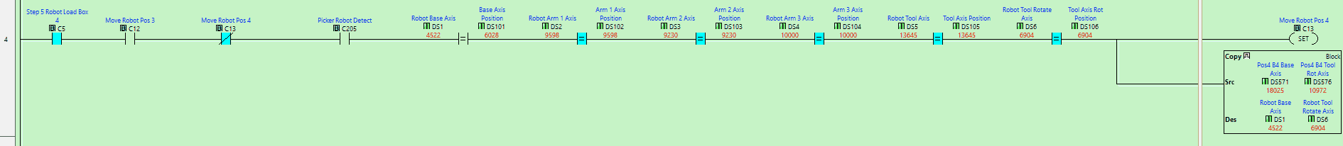
When in step 5 and the robot has been set for position 3, compare the 6 axes of the current position to the set positions. If they are the same, set the robot for position 4 and set a bit (C13) that indicates the robot’s movement to position 4.
Note: Position 4 will have different coordinates for each box.
When in step 5 and the robot has been set for position 4, compare the 6 axes of the current position to the set positions. If they are the same, then set the robot for position 5, reset the robot picker and set a bit (C14) that indicates the robot’s movement to position 5.
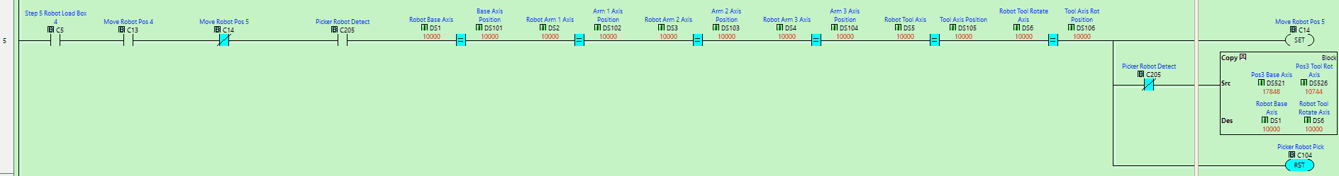
When in step 5 and the robot has been set for position 5, compare the 6 axes of the current position to the set positions. If they are the same, set the robot for the home position. Set bit C15 to indicate the robot’s movement to the home position.
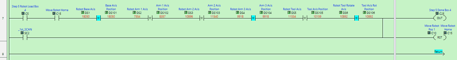
When in step 5 and the robot has been set for the home position, compare the 6 axes of the current position to the set positions. If they are the same, reset the robot position bits C10 to C15 and turn on the step done bit.
Our ladder logic PLC program is complete. Download this to the click PLC with the Click Programming Software and ensure that the PLC is in run mode.
Watch the video below to see this Click PLC program in action.
Test the program: (Step 5 – EasyPLC Robot Loading – Click PLC)
We will use Modbus TCP on our Click PLC to communicate with the EasyPLC Machine Simulator.
Call up the “Robot Loader” machine in start mode.
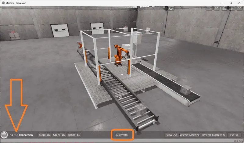
The status of the machine simulator will be at the bottom of the screen. Currently, we have no PLC connected. Select IO Drivers on the bottom middle of the screen.
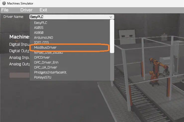
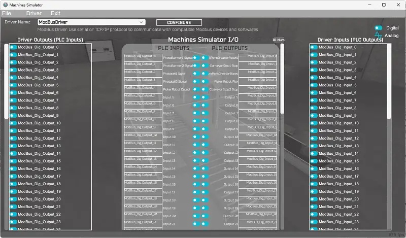
The EasyPLC driver is selected by default. Under the driver pull-down menu, select “ModBusDriver.” This driver will communicate Modbus TCP (Ethernet) and Modbus RTU (Serial).
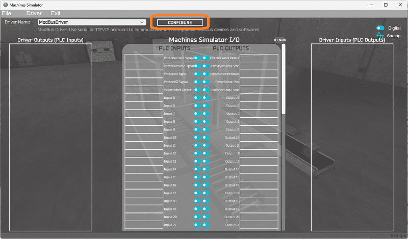
Select the configure button.
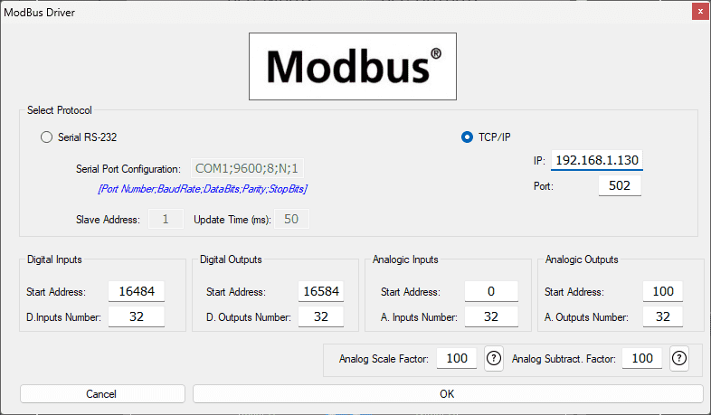
We can now enter the information for our Modbus driver. Select TCP/IP. This means the Ethernet port on the computer will communicate with the PLC.
The digital inputs from MS to the Click PLC will be C101 to C105. This will start at address 16484 due to the offset of 1. Digital outputs from MS to the Do-More PLC will be C201 to C205. This will begin at address 16494 due to the offset of 1. We are indicating 32 digital inputs and outputs. This is fine because it is more than our EasyPLC machine simulator will require.
Analog inputs from MS to the Click PLC will be DS1 to DS6. This will start at address 0 due to the offset of 1. Analog outputs from MS to the Do-More PLC will be DS101 to DS106. This will begin at address 100 due to the offset of 1. Select the OK button.
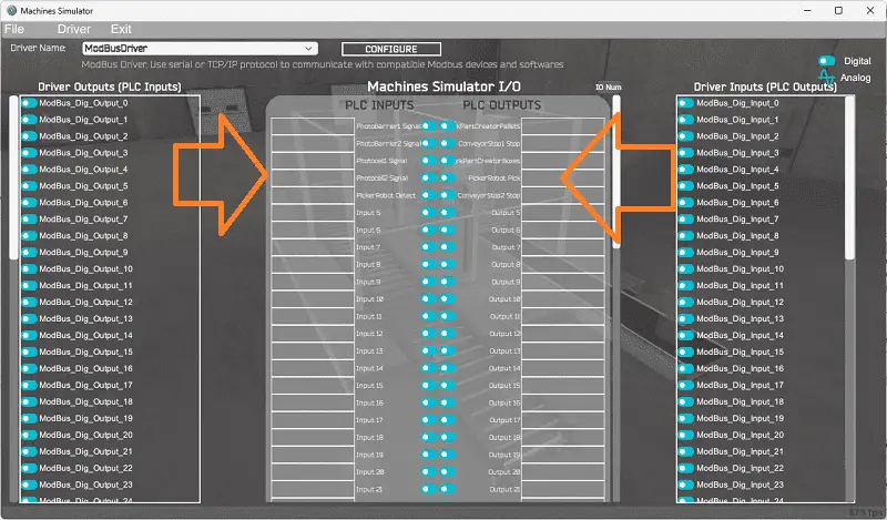
You will now see the inputs and outputs specified for the Modbus driver. We can manually assign the driver outputs to the PLC inputs and the driver inputs to the PLC outputs. However, the automatic assignment works well and will save you time.
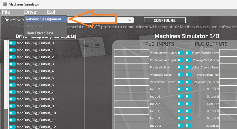
Select Automatic Assignment from the driver option in the main menu.
This will automatically assign the PLC IO to the Machine Simulator IO.
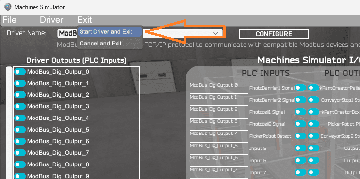
Select start driver and exit from the main menu.
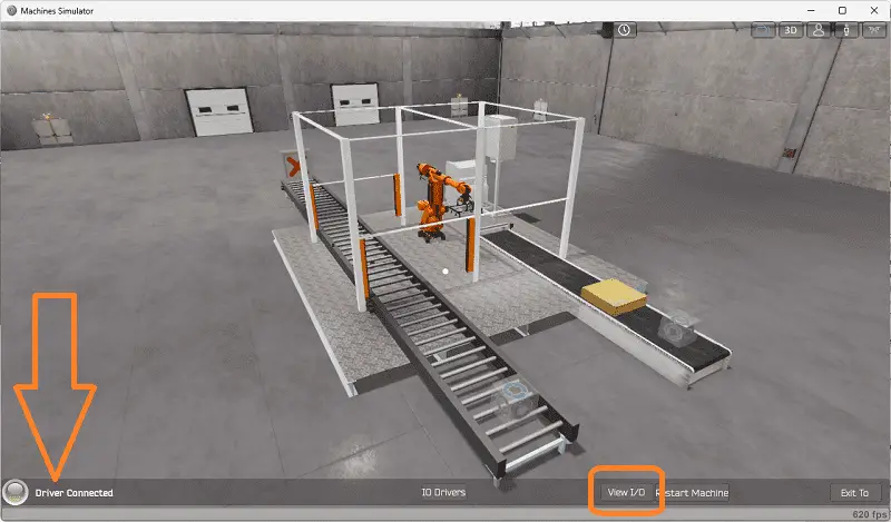
On the bottom left side of the window, you will see that the driver communicates to the PLC with the green light. Select view IO to know the input and output status of the machine simulator.
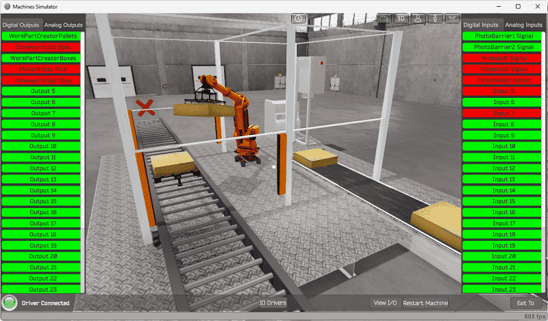
Ensure that the PLC is in run mode. We can now test and operate our EasyPLC robot loader machine.
Move around this virtual environment while you are testing the program.
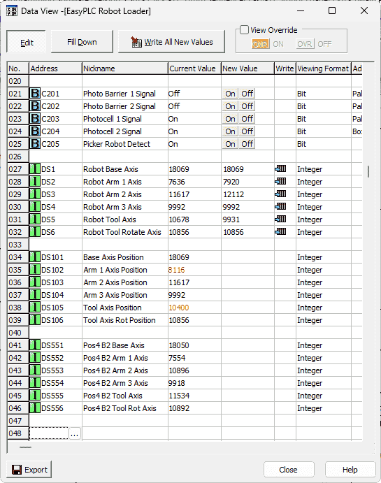
Using the Data View window of the Click PLC programming software, we can also watch the inputs and outputs operate.
Watch the video below to see this operation.
If your program works correctly, it’s time to move on. If not, you’ll need to debug. Monitoring and viewing what is happening in the logic is critical. Looking back on the programming steps, you might have to change your logical sequence and program and test again. This is just part of the process.
When using EasyPLC, debugging is quickly done without damaging any equipment. You may modify your logic several times before you get everything right! To learn more about developing logic, check out our tutorials on the five steps to PLC program development.
You can practice your modification and debug by modifying the robot loader operation in the following way:
– Add a control panel with start and stop buttons
– Add an emergency stop condition that will trigger if the robot moves and the light curtains are tripped. An additional reset button on the control panel must be selected before starting the machine again.
– Calculate the rate of full pallets coming out of the robot loader machine in pallets per hour.
Let me know how you make out in the comments below.
Download the Click PLC sample program and robot positions here.
Watch the video below to see the five steps of program development applied to the robot loading machine. The machine simulator is one of the best applications to help you learn PLC programming.
EasyPLC Software Suite is a complete PLC, HMI, and Machine Simulator package. This PLC learning package includes the following:
Easy PLC – PLC Simulation allows programming in Ladder, Grafcet, Logic Blocks, or Script.
HMI System – Easily create a visual human-machine interface (HMI)
Machine Simulator – A virtual 3D world with real-time graphics and physical properties. PLC programs can be tested using EasyPLC or through other interfaces. (Modbus RTU, TCP, etc.)
Machine Simulator Lite – Designed to run on Android Devices.
Machine Simulator VR – Virtual Reality comes to life so you can test, train or practice your PLC programming.
Purchase your copy of this learning package for less than USD 75 for a single computer install or less than USD 100 to allow different computers.
Receive 10% off the price by typing in ACC in the comment section when you order. http://www.nirtec.com/index.php/purchase-price/
Learn PLC programming the easy way. Invest in yourself today.
Watch on YouTube: PLC Program Sequence for Efficient Robot Loading Operations
If you have any questions or need further information, please contact me.
Thank you,
Garry
If you’re like most of my readers, you’re committed to learning about technology. Numbering systems used in PLCs are not challenging to learn and understand. We will walk through the numbering systems used in PLCs. This includes Bits, decimals, Hexadecimal, ASCII, and Floating points.
To get this free article, subscribe to my free email newsletter.
Use the information to inform other people how numbering systems work. Sign up now.

The ‘Robust Data Logging for Free’ eBook is also available for free download. The link is included when you subscribe to ACC Automation.