Master cylinder control with programmable 500-step sequences! Learn to build a 7-cylinder sequencer using AdvancedHMI and Modbus TCP. Full tutorial included.
We will continue the series by looking at a sequencer controlling seven cylinders that can be taught. The cylinders can be programmed by the operator from the AdvancedHMI screen. You will be able to select what cylinders to activate at each step and program in 500 steps. Our PLC will be a Do-More from AutomationDirect.
Here is a quick review of the programming series so far. If you are new to the site, we recommend reviewing the other parts in the series first.
In part 1 we looked at writing PLC programs to control a traffic light using discrete bits and then using timed sequencing using indirect addressing.
Part 2 used indirect addressing for inputs as well as output to control the sequence of pneumatic (air) cylinders in the program. Part 3 and 4 we returned to the traffic light application and expand our program significantly. We looked at the sequence of operations using Input, output, and mask tables.
In part 5 we used the AdvancedHMI software to create the game of Simon. A round in the game consists of the device lighting up one or more buttons in a random order, after which the player must reproduce that order by pressing the buttons. As the game progresses, the number of buttons to be pressed increases.
Sequence of Operation – Building a PLC Program 6
We will be using AdvancedHMI to communicate Modbus TCP to the Automation Direct Do-More Designer Software Simulator. The following is the sequence of operation:
Watch on YouTube: Running the Cylinder Sequence (PLC / HMI)
Note: All of the programs used are provided free of charge and are an excellent way to learn PLC / HMI programming.
The following table is the Modbus TCP memory map to the Do-More PLC:
| Coil/Register Numbers | Data Addresses | Type | Do-More PLC | Table Name |
| 00001-09999 | 0000 to 270E | Read-Write | MC1 to MC1023 | Discrete Output Coils |
| 10001-19999 | 0000 to 270E | Read-Only | MI1 to MI1023 | Discrete Input Contacts |
| 30001-39999 | 0000 to 270E | Read-Only | MIR1 to MIR2047 | Analog Input Registers |
| 40001-49999 | 0000 to 270E | Read-Write | MHR1 to MHR2047 | Analog Output Holding Registers |
Here are the inputs and outputs we will be using for our program:
| Device | Data Addresses | Type | Do-More PLC | Description |
| Start Pushbutton | 00011 | Input | MC11 | |
| Stop Pushbutton | 00012 | Input | MC12 | |
| Jog Pushbutton | 00013 | Input | MC13 | |
| Reset Pushbutton | 00014 | Input | MC14 | |
| Run/ Jog Selector | 00008 / 00015 | Input/ Output | MC8 / MC15 | MC8 is the value and MC15 is the click |
| Light Stack | 00010 / 00009 / 00008 | Output | MC10 / MC9 / MC8 | Red / Green / Amber |
| Set Pushbutton | 00071 | Input | MC71 | |
| Jog / Teach Selector | 00070 | Input | MC70 | MC70 on is teach mode |
| Sequence Step (Panel Meter) | 40001 | Output | MHR1 | Current step in the sequence |
| Inputs Actual | 40002 | Input | MHR2 | Show the actual inputs in binary format |
| Output Sequence | 40003 | Output | MHR3 | Show the actual outputs in a binary format |
| Input Sequence | 40004 | Input | MHR4 | Show the input sequence bits in a binary format |
| Cylinder 1 to 7 – value | 00001 to 00007 | Output | MC1 to MC7 | Determine if cylinder is on/off |
| Cylinder 1 to 7 – set (click) | 00041 to 00047 | Input | MC41 to MC47 | Set the cylinder button |
| Cylinder 1 to 7 – retract indicators | 00021 to 00027 | Input | MC21 to MC27 | Indicate cylinder has retracted |
| Cylinder 1 to 7 – extend indicators | 00031 to 00037 | Input | MC31 to MC37 | Indicate cylinder has extended |
| Cylinder 1 to 7 – extend / retract error indicators | 00050 to 00063 | Output | MC50 to MC63 | Indicate cylinder input error when jogging |
HMI Design – Building a PLC Program 6
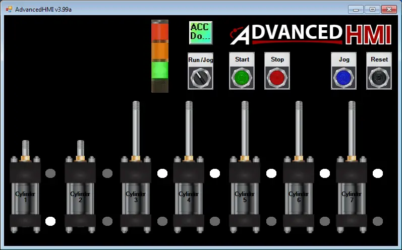
The first thing we will do is design the HMI. We have three main areas on the screen. Basic Controls, Cylinder Visualization, and the Sequence Step/Teach area. Please refer to the above reference chart for the inputs and outputs programmed on the screen.
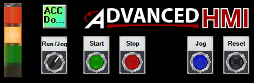
Basic Controls:
This area will allow us to see what mode we are in via the stack light. Red – Stop
Yellow – Jog / Teach Mode – Troubleshooting
Green – Run
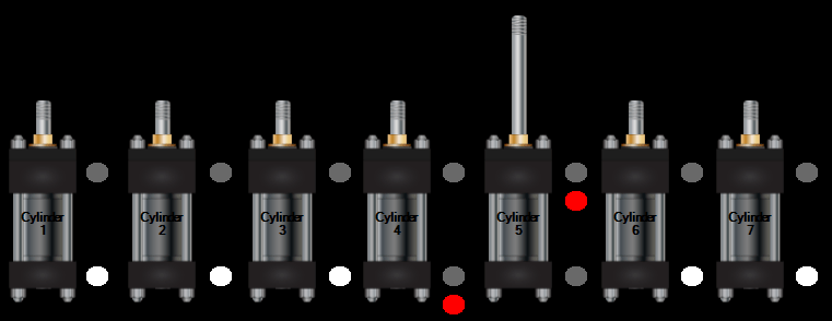
Cylinder Visualization:
Each cylinder will have indication lights to determine the status of the cylinder. (Extended / Retracted)
The cylinder will also have red indication lights to reflect the differences between the current sequence and the next sequence step. This is visible when we are in jog mode.
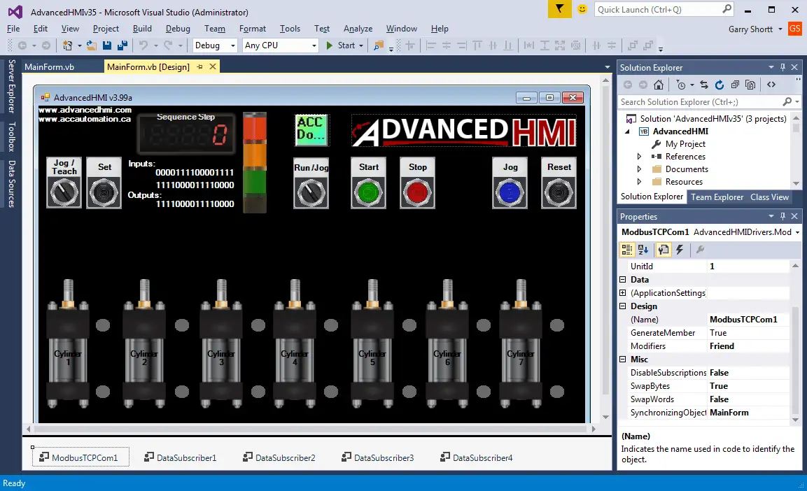
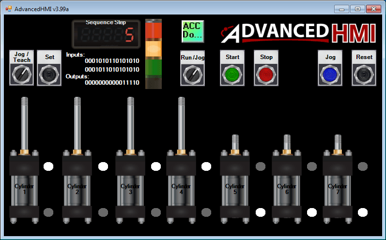
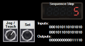
Sequence Step/Teach – Building a PLC Program 6
When in a jog or teach mode the sequence step is visible, which indicates the current step that we are on. The inputs and outputs are displayed as a binary value which represents the actual inputs and outputs. This is valuable when troubleshooting and finding errors in the system. The set button is visible when in teach mode. When pushed the outputs and inputs are set for that step and the sequence will then increment.
The following is the code for each of the words that the DataScribers are reading. This includes the code to change the word into a 16-bit binary value.
Private Sub DataSubscriber1_DataChanged(sender As Object, e As Drivers.Common.PlcComEventArgs) Handles DataSubscriber1.DataChanged
'Label1.Text = Hex(DataSubscriber1.Value)Dim i As Integer = DataSubscriber1.Value
Label1.Text = Convert.ToString(i, 2).PadLeft(16, "0") '16 bits
End Sub
Private Sub DataSubscriber2_DataChanged(sender As Object, e As Drivers.Common.PlcComEventArgs) Handles DataSubscriber2.DataChanged
'Label2.Text = Hex(DataSubscriber2.Value)
Dim i As Integer = DataSubscriber2.Value
Label2.Text = Convert.ToString(i, 2).PadLeft(16, "0") '16 bits
End Sub
Private Sub DataSubscriber3_DataChanged(sender As Object, e As Drivers.Common.PlcComEventArgs) Handles DataSubscriber3.DataChanged
Dim i As Integer = DataSubscriber3.Value
Label3.Text = Convert.ToString(i, 2).PadLeft(16, "0") '16 bits
End Sub
Private Sub DataSubscriber4_DataChanged(sender As Object, e As Drivers.Common.PlcComEventArgs) Handles DataSubscriber4.DataChanged
If DataSubscriber4.Value = True Then
     Label1.Visible = True
     Label2.Visible = True
     Label3.Visible = True
     Label4.Visible = True
     Label5.Visible = True
Else
     Label1.Visible = False
     Label2.Visible = False
     Label3.Visible = False
     Label4.Visible = False
     Label5.Visible = False
End If
End Sub
We will now look at the PLC ladder program. The program is broken down into several parts as follows:
ACC Automation Sample PLC Program – Building a PLC Program 6
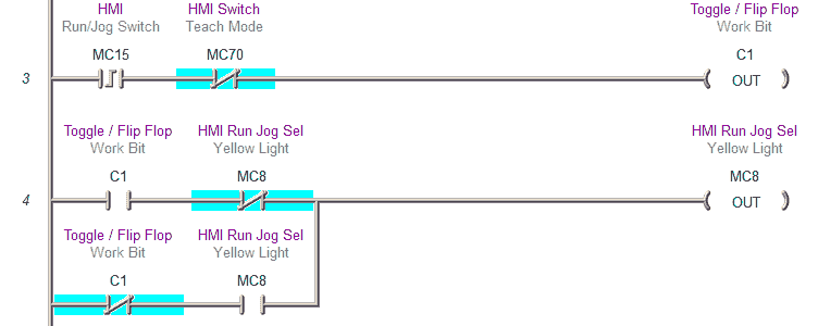
This is the main start / stop circuit of the program.
If we are in run mode the green light will be on. (MC9)
If we are not in jog mode (MC8) this circuit will be functional.
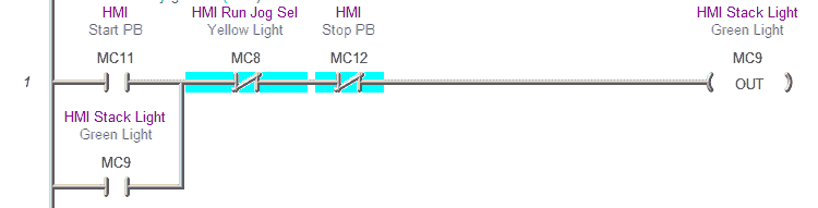
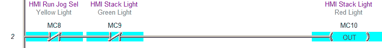
If we are not run mode (MC9) or in jog mode (MC8) then the stop mode is active.
This will turn on the red light. (MC10)
Run / Jog – Toggle Circuit
Flip Flop circuit to set the jog function
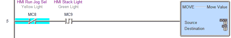
Move the outputs to the physical outputs when we go to run mode.
Indirect Addresses for the Program
V0 – Input pointer – 100 – 499
V1 – Output pointer – 500 – 999
V2 – Input pointer last step in the sequence
V3 – Output pointer last step in the sequence
V10 – Inputs to the sequencer
V20 – Outputs from the sequencer
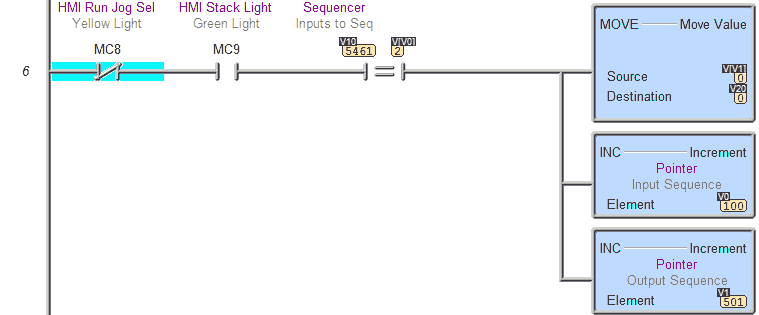
Jog Mode – Jog Pushbutton
Reset the sequencer pointers. This will happen automatically in run mode or by hitting the reset button in jog or stop mode.
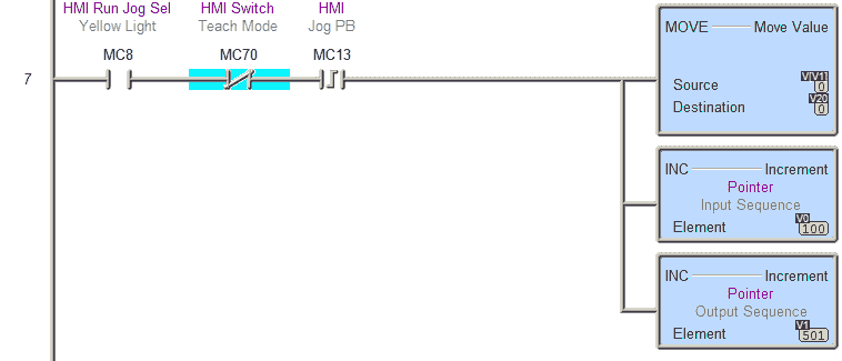
Teach Function – Building a PLC Program 6
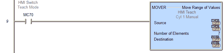
This first rung will activate the values so we can manually turn them off/on with the HMI screen.
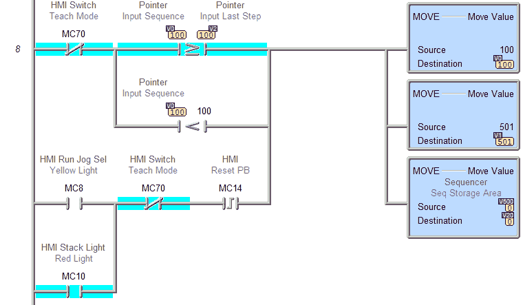
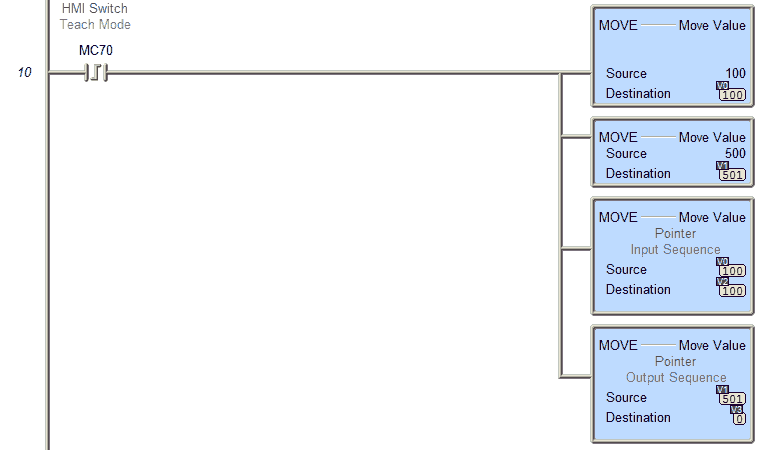
This will reset the pointers when going into teach mode.
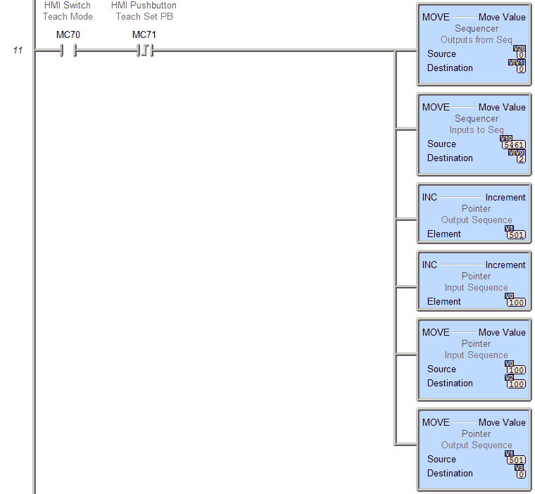
This will set the teach point and increment to the next step.
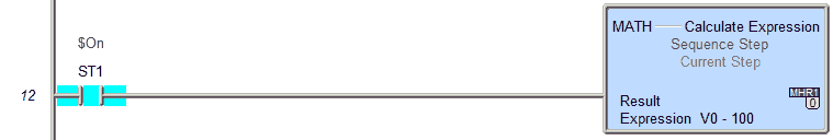
Show the current step of the sequence.
Note: 0 is the first step
Set the inputs for cylinders.
The actual physical input points would be inserted here.
HMI inputs from the cylinders have a 500ms delay to simulate the movement of the actual cylinder.
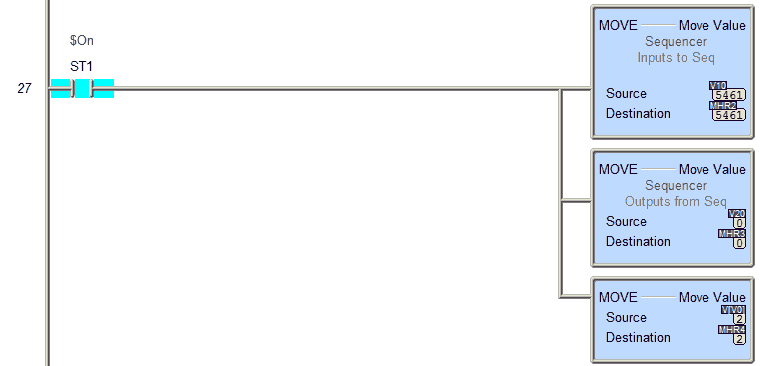
Set the actual inputs/sequencer inputs/sequencer outputs so we can monitor this on the HMI.
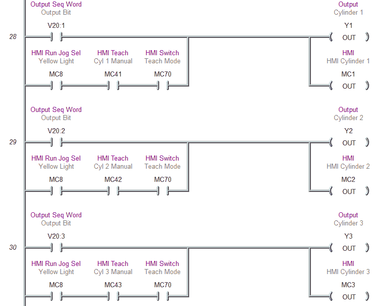
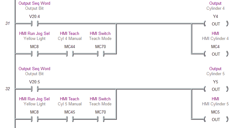
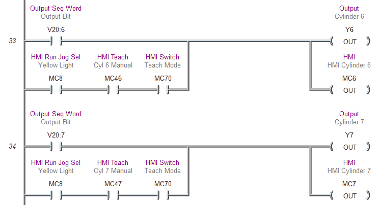
Set the outputs for cylinders.
This will set the physical output points Y1 to Y7.
This will also set the HMI cylinders MC1 to MC7 (00001 to 00007)
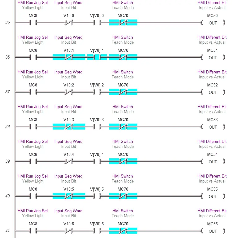
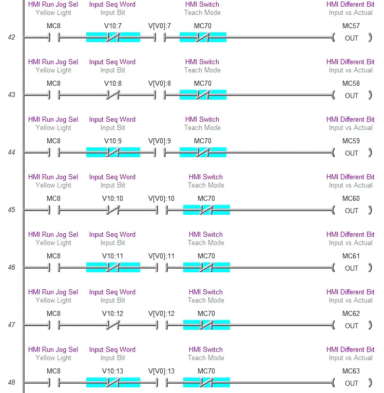
Diagnostic Bits for indicating the difference for the inputs to the PLC. This will show up as a red indicator light on the cylinder represented on the HMI.
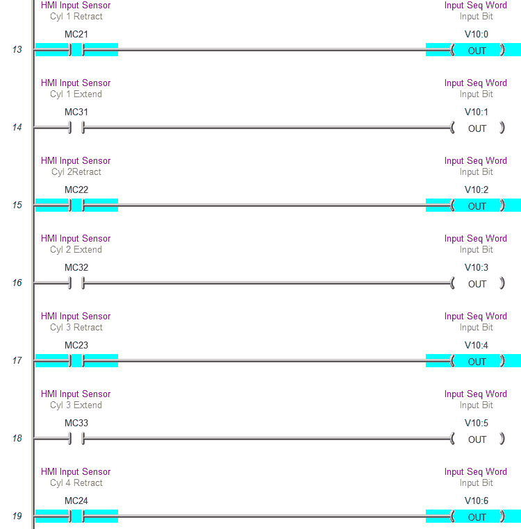
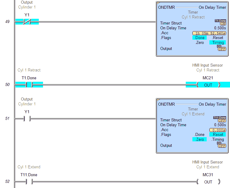
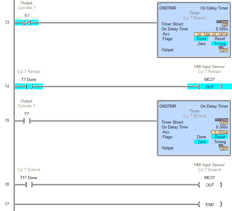
This section of PLC logic will mimic the inputs from the cylinders.
Cylinder 1 – Retract MC21 (00021) – Extend MC31 (00031)
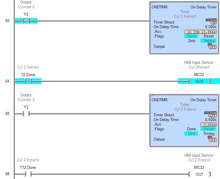
Cylinder 2 – Retract MC22 (00022) – Extend MC32 (00032)
Cylinder 3 – Retract MC23 (00023) – Extend MC33 (00033)
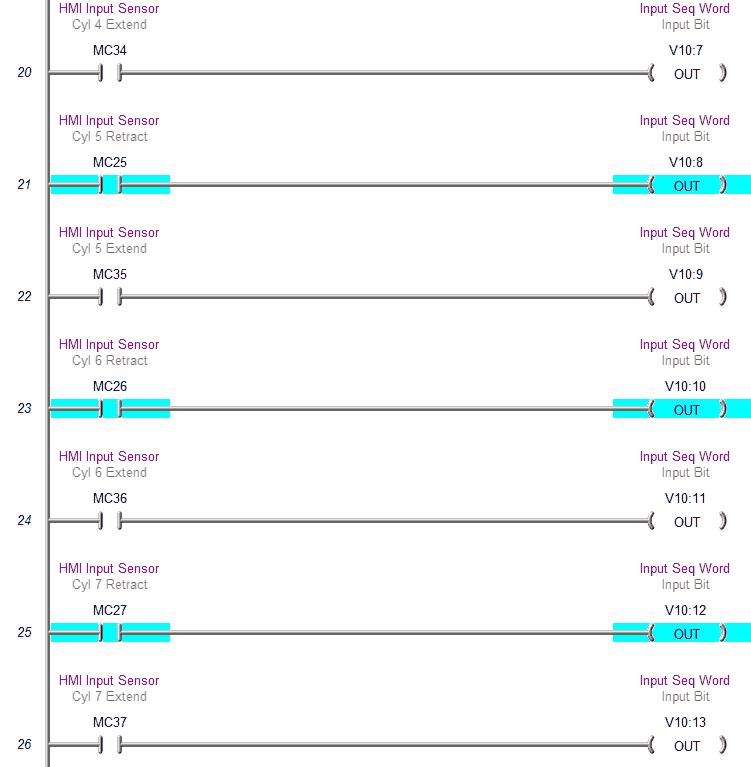
Cylinder 4 – Retract MC24 (00024) – Extend MC34 (00034)
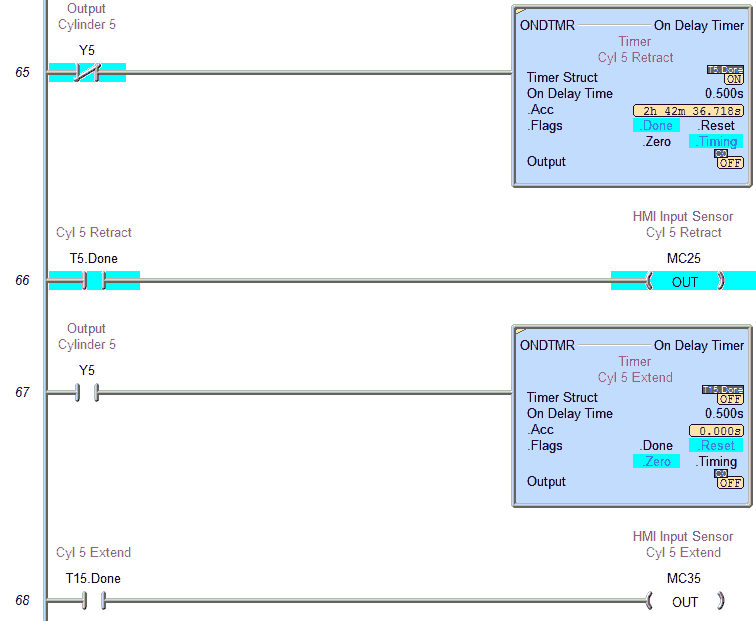
Cylinder 5 – Retract MC25 (00025) – Extend MC35 (00035)
Cylinder 6 – Retract MC26 (00026) – Extend MC36 (00036)
Cylinder 7 – Retract MC27 (00027) – Extend MC37 (00037)
Between each function of the cylinder, there is a time delay for the input to turn on and off of 500msec.
Cylinder 2 – Retract MC22 (00022) – Extend MC32 (00032)
Cylinder 3 – Retract MC23 (00023) – Extend MC33 (00033)

Cylinder 4 – Retract MC24 (00024) – Extend MC34 (00034)

Cylinder 5 – Retract MC25 (00025) – Extend MC35 (00035)
Cylinder 6 – Retract MC26 (00026) – Extend MC36 (00036)

Cylinder 7 – Retract MC27 (00027) – Extend MC37 (00037)
This is the end of the PLC program. You can see that the program is not very complicated once you break down the individual steps.
Download the PLC program and the Bin directory for the AdvancedHMI screen.
Watch on YouTube: Building a PLC Program that You can be Proud Of – Part 6b – Explaining the Program
If you have any questions or need further information please contact me.
Thank you,
Garry
If you’re like most of my readers, you’re committed to learning about technology. Numbering systems used in PLC’s are not difficult to learn and understand. We will walk through the numbering systems used in PLCs. This includes Bits, Decimal, Hexadecimal, ASCII and Floating Point.
To get this free article, subscribe to my free email newsletter.
Use the information to inform other people how numbering systems work. Sign up now.

The ‘Robust Data Logging for Free’ eBook is also available as a free download. The link is included when you subscribe to ACC Automation.