Master PLC Pick & Place: 5-Step Robot Programming Guide
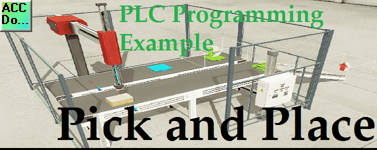
We will apply the five steps to PLC program development to a pick and place robot example. The example will use a BRX PLC communicating to Factory IO (3D Software Simulator). Developing the PLC program is a process that can be clearly defined. In our series on the five steps to PLC program development, we … Read more