We will now look at bitmap images that we can display on our C-More Micro unit. The C-More Micro HMI Panel software uses virtual components called Objects. Bitmaps are part of these objects. These bitmaps are images that are made up of tiny dots called pixels. Each of these dots are actually a small square that contains one colour. Bitmaps will help you produce simple, intuitive looking human machine interfaces.
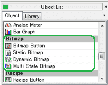
We will now look at bitmaps that we can use with our HMI micro panel. They include bitmap buttons, static bitmap, dynamic bitmaps and multi-state bitmaps. Let’s get started.
Previously in this C-More Micro HMI Panel series we have done the following:
System Hardware – Video
Installing the Software – Video
– Update Automation Direct Software C-More Micro HMI Video
System Setup Screens – Video
First Program – Video
First Program Part 2 (PLC < – > Panel) – Video
Common Screen Menu – Video
Simulate Project – Video
Object List Shapes – Video
Object Buttons and Indicators – Video
Object Numeric Entry – Video
Object Meters and Graphs – Video
Setting Our C-More Micro Bitmap Page
We will be using the program we created last time. (C-More Micro HMI Object Meters and Graphs).
Under the Navigation panel we will create a new screen. (Screen 9)
On the screen tab under the navigation panel select New Screen. (Ctrl + N)
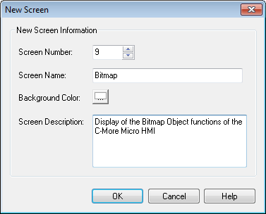
Screen Name: Bitmap
Screen Description – We can describe the purpose of the screen.
Select OK.
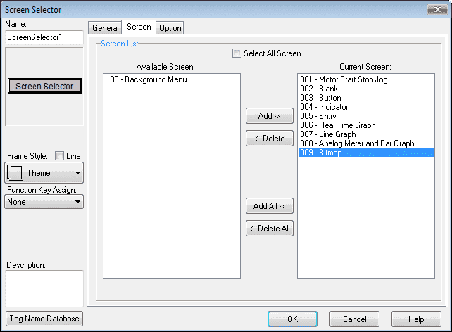
Set the background screen for our new pages to page 100. This was first shown in the post Common Screen Menu – Video.
Select the “Screen Selector” button on screen 100. Add the three new screens so we can navigate to them.
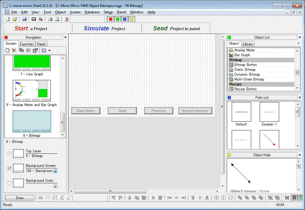
We now have our pages to start adding bitmaps.
Tag Name Database – C-More Micro Bitmap
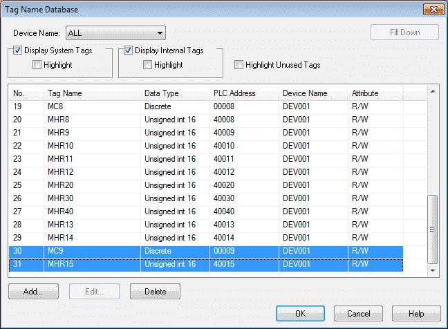
We will use the following addresses to control the bitmap objects on the cmore micro HMI. Add this to our tag database.
MC9 – Modbus Address 00009 – Discrete – Read / Write
MHR15 – Modbus Address 40015 – 16 bit unsigned – Read / Write
Bitmap Image Button – C-More Micro
The Bitmap Button Object uses a one-bit (ON/OFF) Bitmap graphic to perform the functions of a Pushbutton. The Bitmap Button Object can be assigned to a Tag Name and used to activate or deactivate components.
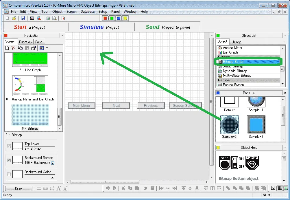
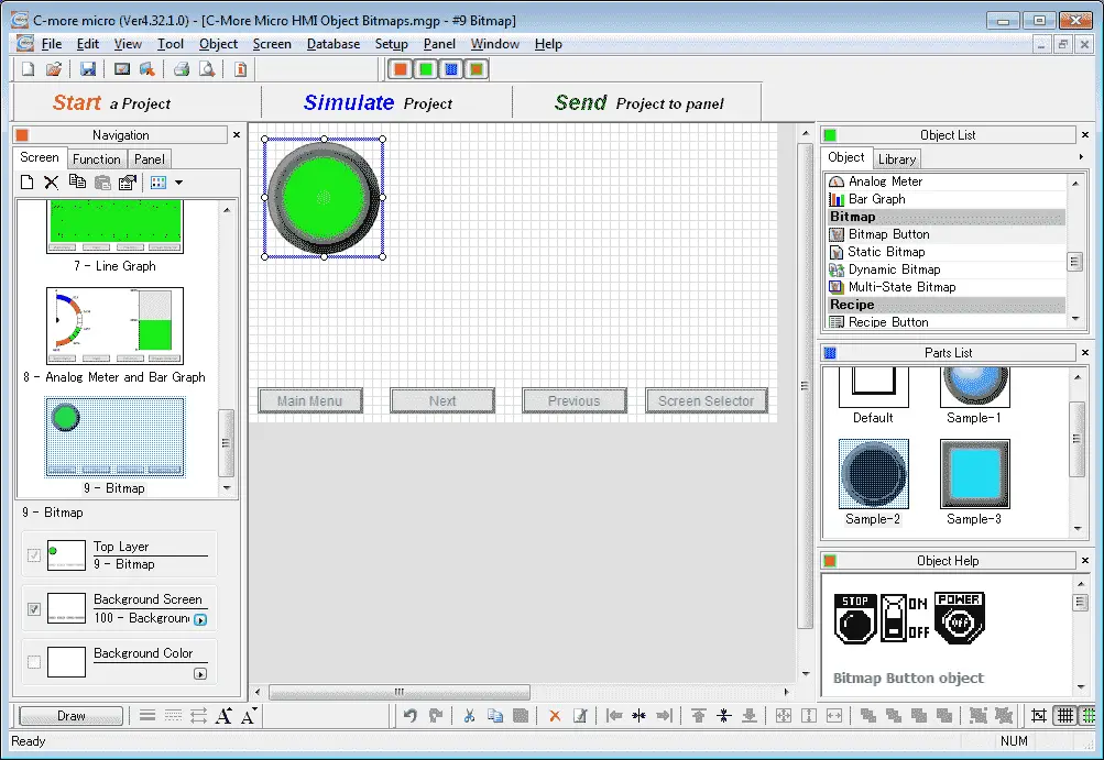
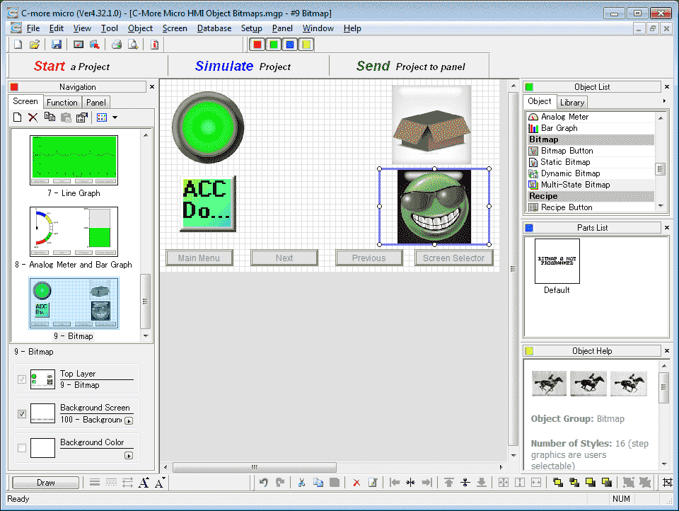
Select screen 9 from the navigation window. Select Bitmap Button under the Bitmap heading in the Object list. Now click and hold Sample-2 from the parts list and drag onto our screen.
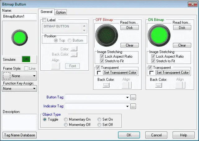
Name: – The default name is BitmapButton1. Change the name on the field by clicking and typing a new name.
Object Preview Window: – This is a smaller display of what the changes are as you make them on the Bitmap Button window.
Description: – Enter up to 400 characters to describe this bitmap button object.
Tag Name Database: – This button allows you to add, edit or delete tag names.
Label: – This is the display title of the bitmap button.
OFF Bitmap – Import images to be used for the OFF Bitmap. This will be the image displayed when the object is OFF.
ON Bitmap – Import images to be used for the ON Bitmap. This will be the image displayed when the object is On.
Disk – Click on this button to select an image on your PC (Disk).
Clear Button – Select Clear to remove a selection.
Image Stretching – Lock Aspect Ratio – Click on this checkbox to maintain the Ratio of the graphic. This keeps the graphic proportional when changing the X or Y Axis. The object frame will change size, but the graphic will stay proportional. For best results keep both options selected. This feature is selected as default with TFT panels.
Image Stretching – Stretch to Fit – Click on this checkbox to stretch the graphic to fit the frame. For best results keep both options selected. This feature is selected as default with TFT panels.
Transparent – This feature is available only for TFT color panels; NOT available for STN (monochrome) panels. Click the Transparent checkbox to allow you to identify an area in the bitmap to be Transparent. Note that a single color is designated to be transparent. On bitmaps using the full 32000 colors, imperceptible variations in colour may become significant with this setting. To set a Transparent Colour on a bitmap, click on the Set Transparent Color button.
Button Tag – Click on the down arrow to select a Tag Name or use the same (recommended if using internal tags), or by using different Tag Names, the PLC can be programmed to confirm the button signal was received.
Indicator Tag – Click on the down arrow to select a Tag Name or use the same (recommended if using internal tags), or by using different Tag Names, the PLC can be programmed to confirm the button signal was received.
Object Type – The Object Type option allows the user to choose between five types of operation for the Bitmap Button. The five choices are:
– Toggle – The Toggle choice will Toggle the Bitmap Button operation between ON and OFF every time the Bitmap Button is selected (pressed).
– Momentary On: This selection causes the Bitmap Button to be ON while the Bitmap Button is pressed. As soon as the button is released it returns to the OFF state.
– Momentary Off: This selection causes the Bitmap Button to be OFF while the Bitmap Button is pressed. As soon as the button is released it returns to the ON state.
– Set On: This selection causes the Bitmap Button to be set to the ON state when the Bitmap Button is pressed. Once it is set to ON it remains ON until a separate device, such as another Bitmap Button or signal from the PLC turns it Off.
– Set Off: This selection causes the Bitmap Button to be set to the OFF state when the Bitmap Button is pressed. Once it is set to OFF it remains OFF until a separate device, such as another Bitmap Button or signal from the PLC turns it on.
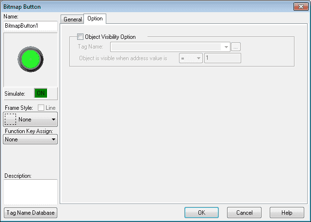
The option tag on the bitmap button window will allow you to specify a tag name that will turn the visibility of the object on or off.
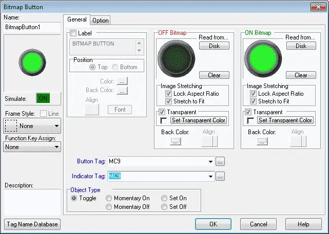
In our example we will use MC9 as the button and indicator tag. The object type will be set for toggle. Select OK.
We can now position and resize the bitmap button object on our screen using our mouse.
Static Bitmap C-More Micro
The Static Bitmap is used to display a Bitmap graphic on a screen. The Static Bitmap is for display purposes only and does not have any functions.
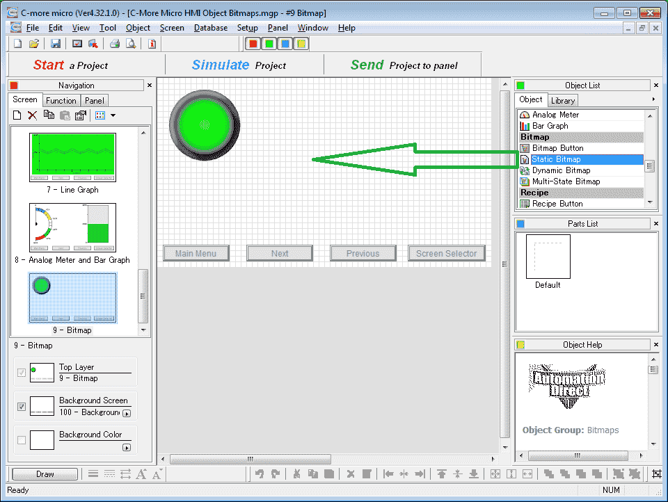
Select Static Bitmap under the Bitmap heading in the Object list. Now click and hold this object and drag it onto our screen.
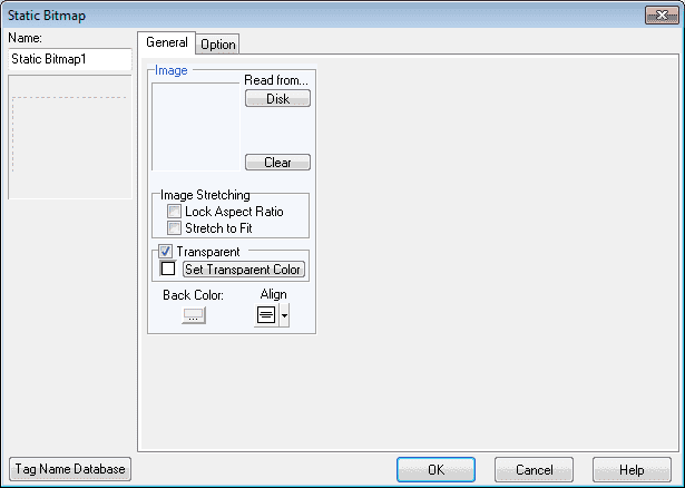
The options in our Static Bitmap window are similar to the bitmap on/off options from the Bitmap Button discussed above.
Hit the read from Disk button.
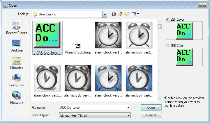
We will select the ACC Do_.bmp image file. Leave the 32K Colour setting as the default. Select Open.
Note: You may have to watch the bitmap files that are selected. They can be very large in size. This will use up your memory in the C-More Micro HMI.
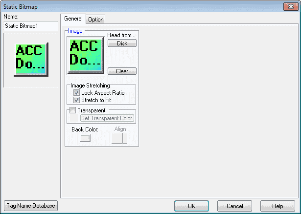
Click the lock aspect ratio and stretch to fit options. Select OK.
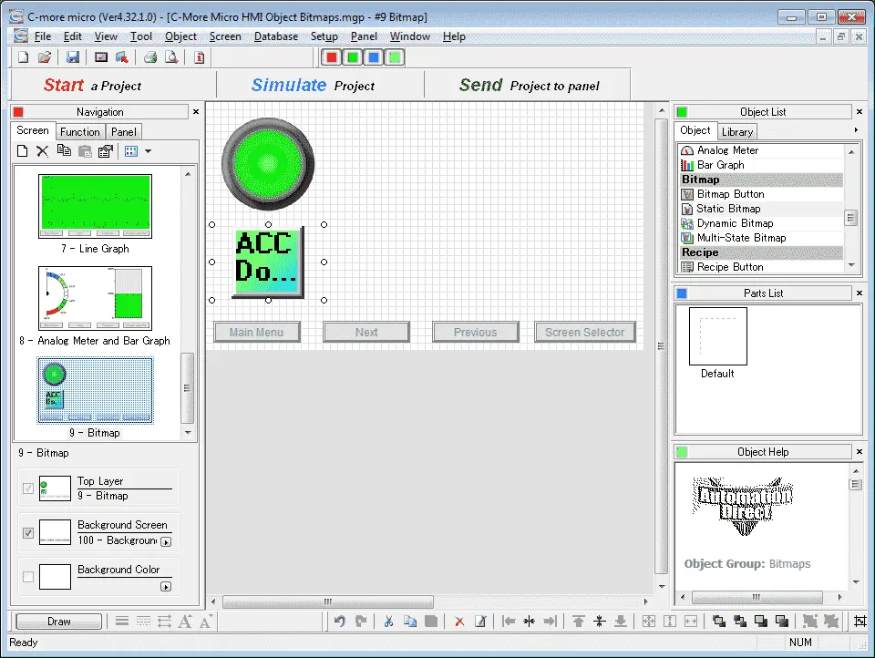
We can now position and resize the static bitmap object on our screen using our mouse.
Static bitmaps are useful in combination with bar graphs. Watch the video below to see a static bitmap of a cylinder and a bar graph combined.
Dynamic Bitmap – C-More Micro
The Dynamic Bitmap Object uses two bitmaps to create an object that toggles between the bitmaps based on the ON/OFF status of a tag.
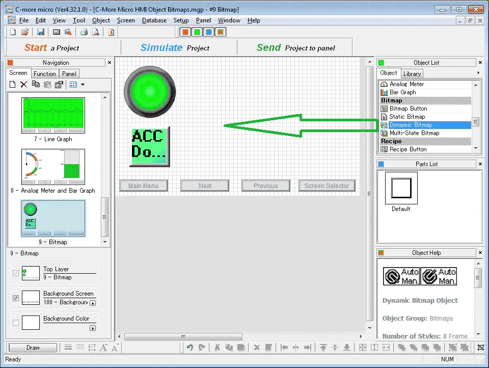
Select Dynamic Bitmap under the Bitmap heading in the Object list. Now click and hold dynamic bitmap and drag it onto our screen
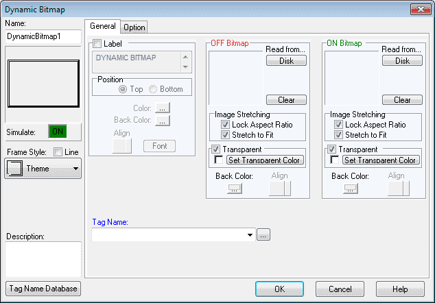
Set the OFF Bitmap to the user graphic box_ver3.bmp. The ON Bitmap is set for box_ver2.bmp in the User Graphic folder. The tag name to determine what bitmap to display will come from the tag name MC9.
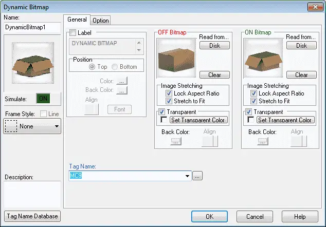
Check the lock aspect ratio and stretch to fit options so the graphic will be proportioned correctly. Select OK.
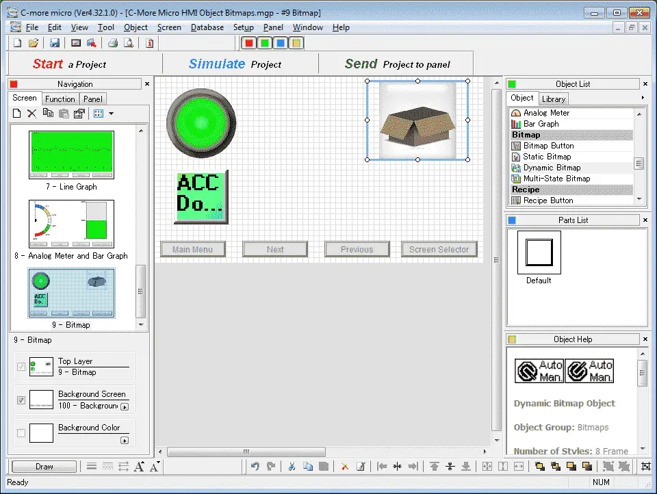
Position and resize the dynamic bitmap object on our screen using the mouse.
Multi-State Bitmap – C-More Micro
The Multi-State Bitmap Object is used to display a Frame with Bitmap Images. This Object includes an Image Tab where the user can enter Image Selections configured to display according to the assigned Tag Names or Bit Numbers.
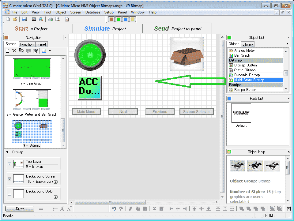
Select Multi-State Bitmap under the Bitmap heading in the Object list. Now click and hold multi-state bitmap and drag it onto our screen.
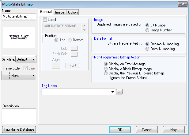
Select the display images are based on image number. Select the image tab.
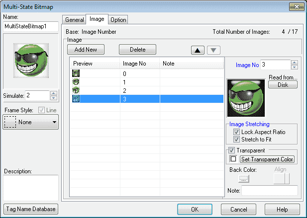
We will call up the four ‘Smiley’ bitmaps and lock the aspect ratio and stretch to fit the image. Select the general tab.
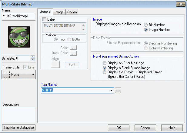
The tag name will be MHR15. This will contain the number of the image that we would like to display. Changing the number will change the picture. Select OK.
Position and resize the multi-state bitmap object on our screen using the mouse.
PLC Program Additions – C-More Micro Bitmap Image
Using the program we previously developed, we will add additional rungs to the program for our Bitmap Objects.
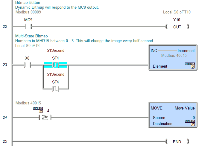
MC9 will control output bit Y10. This will be done with the bitmap button. The dynamic bitmap will also respond to the state of MC9.
The multi-state bitmap will be controlled by the value in MHR15. This value will be incremented every ½ second. The value in the register will be between 0 and 4 to display each of our pictures.
Download the PLC and C-More Micro program here.
Watch the video below to see the Bitmap Objects in action on our C-More Micro HMI Panel. This will also demonstrate the PLC ladder code for functionality and the simulator.
C-More Micro Panels from Automation Direct
https://www.automationdirect.com/adc/Shopping/Catalog/HMI_(Human_Machine_Interface)/C-more_Micro_Panels
C-More Micro – Graphic Panel (EA3 Series) User Manual and Quick Start Guides
https://cdn.automationdirect.com/static/manuals/ea3mguserm/ea3mguserm.html
EA3-T4CL C-More Micro Specifications
https://cdn.automationdirect.com/static/specs/ea3t4cl.pdf
C-More Micro Programming Software V4.30
http://support.automationdirect.com/products/cmoremicro.html
This free software will enable you to program all of the C-More Micro HMI units. It includes a simulator for your application.
Next time we will look at recipe objects in the C-More Micro HMI Panel.
Watch on YouTube: C-More Micro HMI Object Bitmap
If you have any questions or need further information please contact me.
Thank you,
Garry
If you’re like most of my readers, you’re committed to learning about technology. Numbering systems used in PLC’s are not difficult to learn and understand. We will walk through the numbering systems used in PLCs. This includes Bits, Decimal, Hexadecimal, ASCII and Floating Point.
To get this free article, subscribe to my free email newsletter.
Use the information to inform other people how numbering systems work. Sign up now.

The ‘Robust Data Logging for Free’ eBook is also available as a free download. The link is included when you subscribe to ACC Automation.