We will now look at buttons and indicators that we can use on our C-More Micro HMI. The C-More Micro HMI Panel software uses virtual components called Objects. These objects are programmable to simulate the functions that you require on your automation project. Several of these objects can be placed on a one-panel screen and you can have multiple panel screens. This helps you produce simple, intuitive looking human-machine interfaces.
Continuing from last time we will now look at the buttons and indicators that we can use with our HMI micro panel. Let’s get started.
Previously in this C-More Micro HMI Panel series, we have done the following:
System Hardware – Video
Installing the Software – Video
– Update Automation Direct Software C-More Micro HMI Video
System Setup Screens – Video
First Program – Video
First Program Part 2 (PLC < – > Panel) – Video
Common Screen Menu – Video
Simulate Project – Video
Object List Shapes – Video
Setting Our Pages – C-More Buttons and Indicators
We will be using the program we created last time. (C-More Micro HMI Object List Shapes – Video).
Under the Navigation panel, we will create two new pages. (Page 3 – Buttons and Page 4 – Indicators)
On the screen tab under the navigation panel select New Screen. (Ctrl + N)
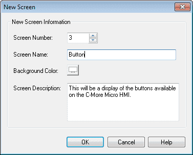
Screen Name: Button
Screen Description – We can describe the purpose of the screen.
Select OK.
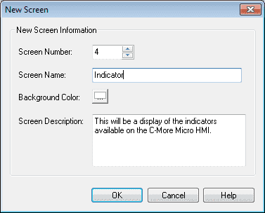
Now add another new screen 4 and call it Indicator.
Select OK.
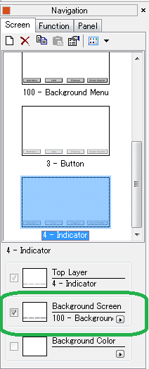
Set the background screen for each of our new pages for page 100. This was first shown in the post-Common Screen Menu – Video.
Select the “Screen Selector” button on screen 100. Add the Button and Indicator screen so we can navigate to these new screens.

We now have our pages to start adding buttons and indicators.
Tag Name Database – C-More Buttons and Indicators
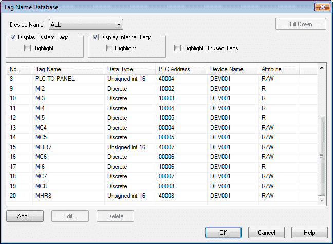
We will use the following addresses to control the buttons and indicators objects on the cmore micro HMI.
MC4 – Discrete On/Off – Modbus Address 00004 – Read / Write (Pushbutton)
MC5 – Discrete On/Off – Modbus Address 00005 – Read / Write (Switch)
MHR7 – Modbus Address 40007 – 16 bit unsigned – Read / Write (Radio Button)
MC6 – Discrete On/Off – Modbus Address 00006 – Read / Write (Indicator Button)
MI6 – Discrete On/Off – Modbus Address 10006 – Read Only (Indicator Button Light)
MC7 – Discrete On/Off – Modbus Address 00007 – Read / Write (Tri-State Switch)
MC8 – Discrete On/Off – Modbus Address 00008 – Read / Write (Tri-State Switch)
MI2 – Discrete On/Off – Modbus Address 10002 – Read Only (Indicator Light)
Note: Address used last time in program to control visibility of shape. (X4)
MI3 – Discrete On/Off – Modbus Address 10003 – Read Only (Graphic Indicator Light)
Note: Address used last time in program to control visibility of shape. (X5)
MHR8 – Modbus Address 40008 – 16 bit unsigned – Read / Write (Numeric Display)
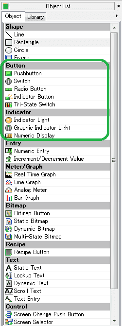
C-More Micro Button Objects
Button objects refer to single bits in the PLC. We can control these discrete tags by using a button object to turn them on (1) or off (0).
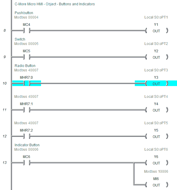
C-More Micro Pushbutton
The pushbutton object is an electronic version of a typical pushbutton normally found on control panels. This pushbutton object can be assigned a tag name and used to activate or deactivate bits in the PLC.
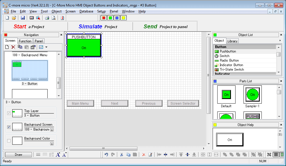
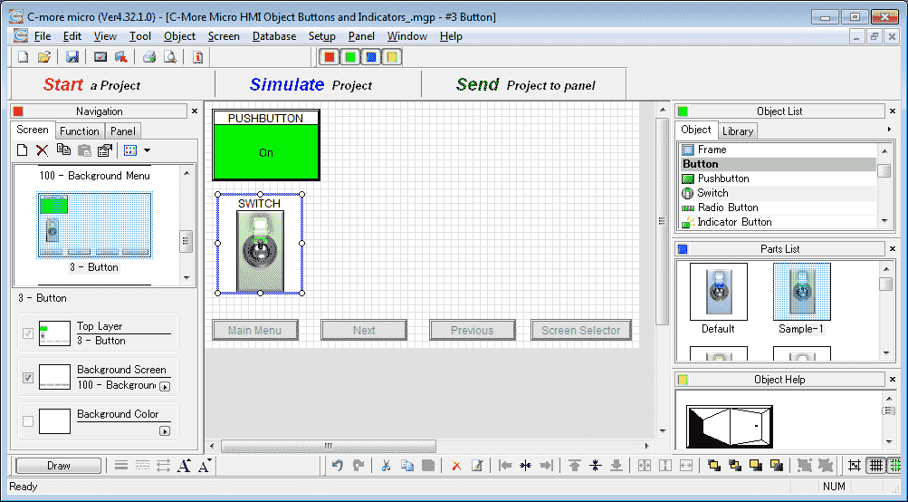
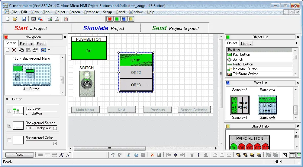
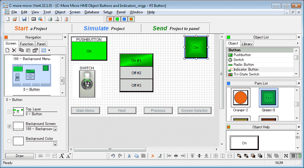
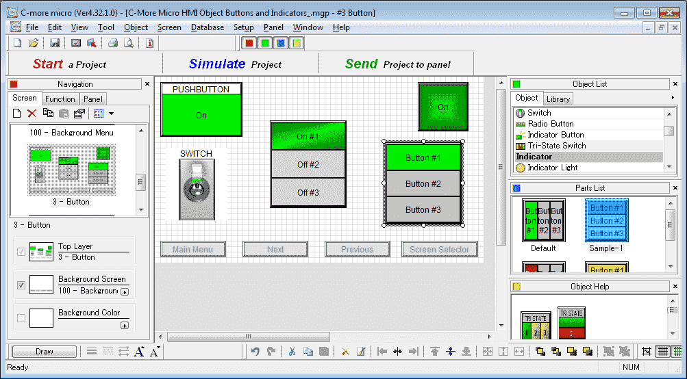
Select Screen 3 from the navigation window. We will now add a Pushbutton under the Object list window. You can left-click (hold) and drag the Pushbutton onto the screen or double click the Pushbutton selection.
The Pushbutton screen window will display. You can also use the main menu | Object | Button | Pushbutton… and click on the work area of the screen.
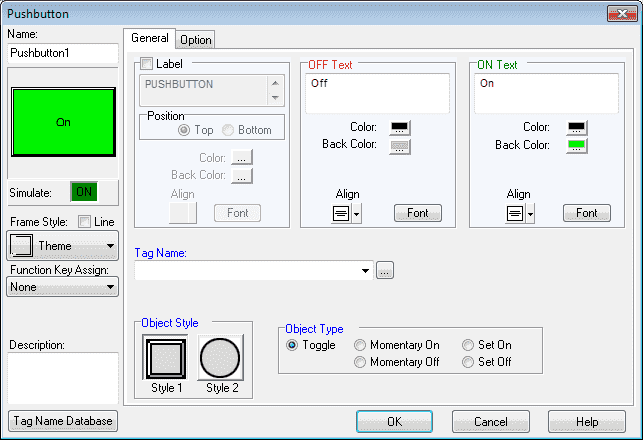
The following parameters can be set:
Name: This is the name of the object. The default is Pushbutton1
Object Preview Window: This will show what the object will look like on the screen.
Simulate: This is used to test the function of the pushbutton object. Click the ON or OFF box to simulate.
Frame Style: The pushbutton object can be displayed in a series of frames. The theme is the default value.
Function Key Assign: Click the down arrow to show a drop-down menu of Function key choices from F1 to F10 that can be assigned to the pushbutton object. Since we have a touch screen we will leave the selection as none.
Description: We can enter up to 400 words to describe the purpose of the pushbutton that we are programming.
Tag Name Database: This will open a window that allows you to add, edit, or delete tag names.
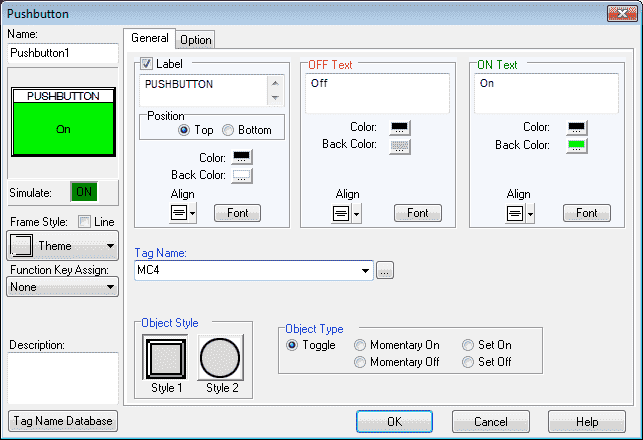
General Tab
Label: This will add a label to the pushbutton. We will select this and leave the default name of PUSHBUTTON in the label text field. The position of the label will be Top and we will leave the default colour, alignment, and font.
OFF Text: This will allow us the change the text that will appear on the pushbutton when the object is off. We will leave the default values for the text, colour, background colour, alignment, and font.
ON Text: This will allow us the change the text that will appear on the pushbutton when the object is on. We will leave the default values for the text, colour, background colour, alignment, and font
Tag Name: This is the tag name of the bit that we will be controlling with the pushbutton. The right button next to the drop-down menu will open a window that allows you to add, edit, or delete tag names. Select MC4 (Modbus Address 00004)
Note: Only the tags that can be used with the pushbutton are displayed.
Object Style: You can select your preferred style. We will leave this as the default of Style 1.
Object Type: This allows us to choose between five types of operation for the pushbutton object. We will leave this as the default toggle.
– Toggle: The toggle will alternate between ON and OFF every time the pushbutton is pressed.
– Momentary On: The pushbutton will be on when the pushbutton is being pressed. As soon as the button is released it turns to the OFF state.
– Momentary Off: The pushbutton will be off when the pushbutton is being pressed. As soon as the button is released it turns to the ON state.
– Set On: The state of the pushbutton will be ON when pressed. It will remain ON until a separate device like another pushbutton or signal from the PLC turns it OFF.
– Set Off: The state of the pushbutton will be OFF when pressed. It will remain OFF until a separate device like another pushbutton or signal from the PLC turns it ON.
Option Tab
Object Visibility Option: We can use this selection to configure a tag to control when the object appears on the screen. C-More Micro HMI Object List Shapes – Video will demonstrate how we use this option.
Click OK. We can now position and resize the Pushbutton object on our screen using our mouse.
Note: When the pushbutton object is selected, we can choose a pre-configured part from the Parts List window. This will save time when configuring objects. Click and drag the item from the parts list to the screen. All of the objects will have a parts list.
C-More Micro Switch
The switch object is an electronic version of a typical switch normally found on control panels. This switch object can be assigned a tag name and used to activate or deactivate bits in the PLC. There are 7 basic and 21 enhanced styles of switches that you can choose. We will now add a switch to our screen.
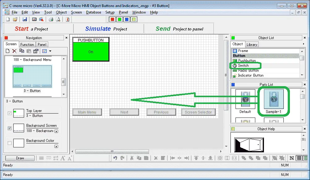
Select switch from the Object List under Button. Now click and hold Sample-1 from the parts list and drag onto our screen.
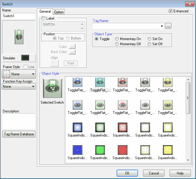
The Switch window now appears. This is similar in allot of the items that we have already programmed for the pushbutton object above. The object style has many more items to choose from to suite your needs.
Enhanced: This will change the object style selections between the 7 basic and 21 enhanced styles of switches.
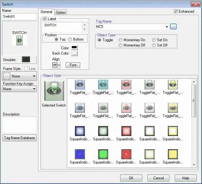
Select the label and leave the text, position, colour, background colour, alignment and font as default. Our tag name will be MC5 (Modbus Address 00005).
Select OK.
We can now use the mouse and size and move our switch object.
C-More Micro Radio Button
The radio button object has 2 to 16 buttons. Only one button can be selected at any time.
We will now add a radio button to our screen.
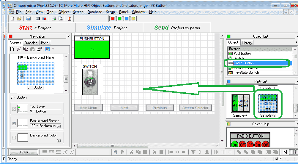
Select radio button from the Object List under Button. Now click and hold Sample-5 from the parts list and drag onto our screen.
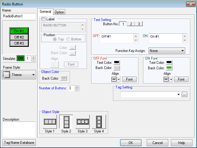
The radio button window will now appear. These object windows will all have a similar look and feel.
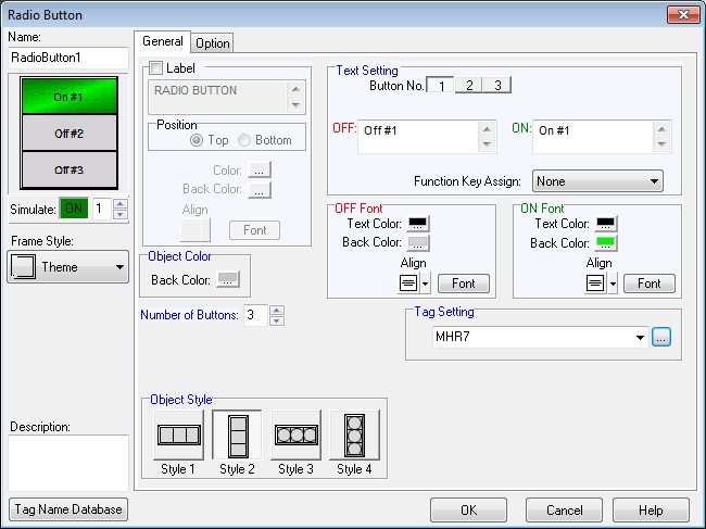
We will set the Tag Setting to MHR7 (Modbus Address 40007). This is an unsigned 16-bit address that will turn on a bit to represent the button selected. (Maximum of16 buttons.)
Select OK.
We can now use the mouse and size and move our radio button object.
C-More Micro Indicator Button
The indicator button is a combination of a pushbutton and an indicator light. We can assign two different tags for each of the functions of this object. Let’s add our indicator button to our screen.
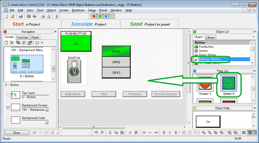
Select indicator button from the Object List under Button. Now click and hold Green-3 from the parts list and drag onto our screen.
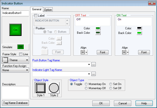
The indicator button window will now appear.
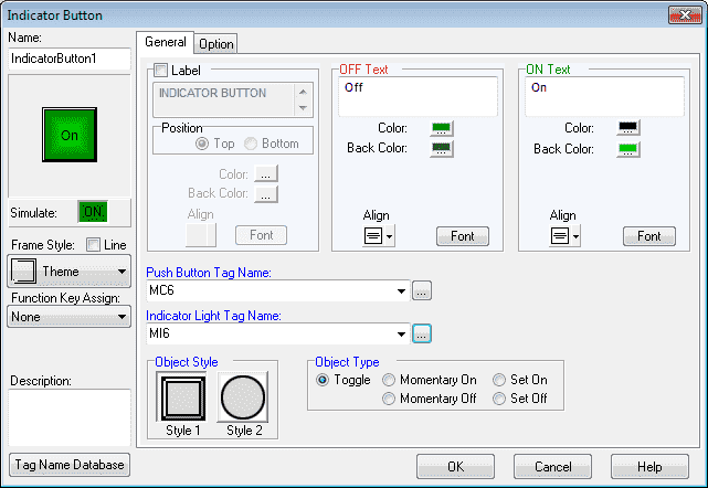
We will set the Push Button Tag Name to MC6. (Modbus Address 00006) The Indicator Light Tag Name will be MI6. (Modbus Address 10006) All of the other parameters we will leave as their default. Select OK.
We can now use the mouse and size and move our indicator button object.
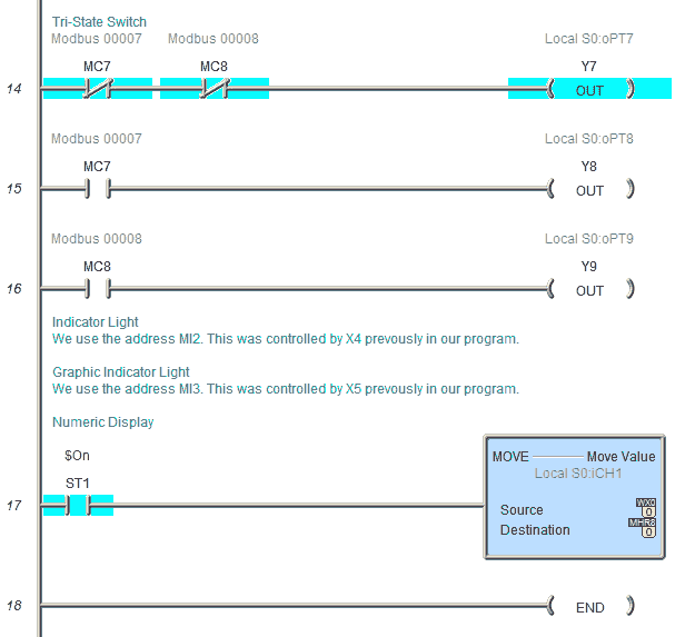
C-More Micro Tri-State Switch
The Tri-State Switch Object is a set of three pushbuttons where the left button is a Reset that turns off both other buttons. We will add a tri-state switch to our screen.
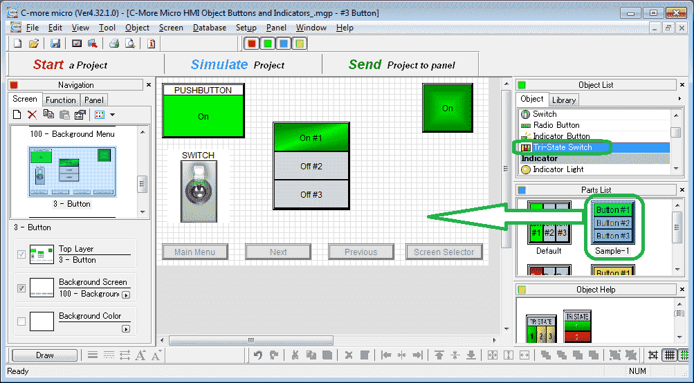
Select Tri-State Switch from the Object List under Button. Now click and hold Sample-1 from the parts list and drag onto our screen.
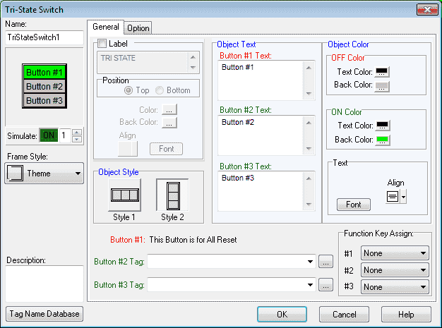
The tri-state switch window will now appear.
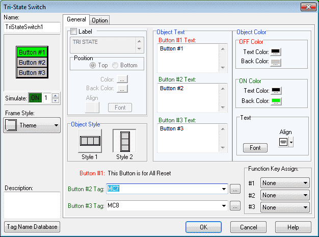
We will use MC7 (Modbus Address 00007) for Button #2 Tag and MC8 (Modbus Address 00008) for Button #3 Tag. All of the other parameters will be left as their default values.
Note: Button #1 is used to turn off both the other buttons.
Select OK.
We can now use the mouse and size and move our tri-state switch object.
C-More Micro Indicator Objects
Indicator Objects consist mainly of information display and condition indication. This will allow you to create Light Indicators that show the operation status of a component/process or Numeric Display.
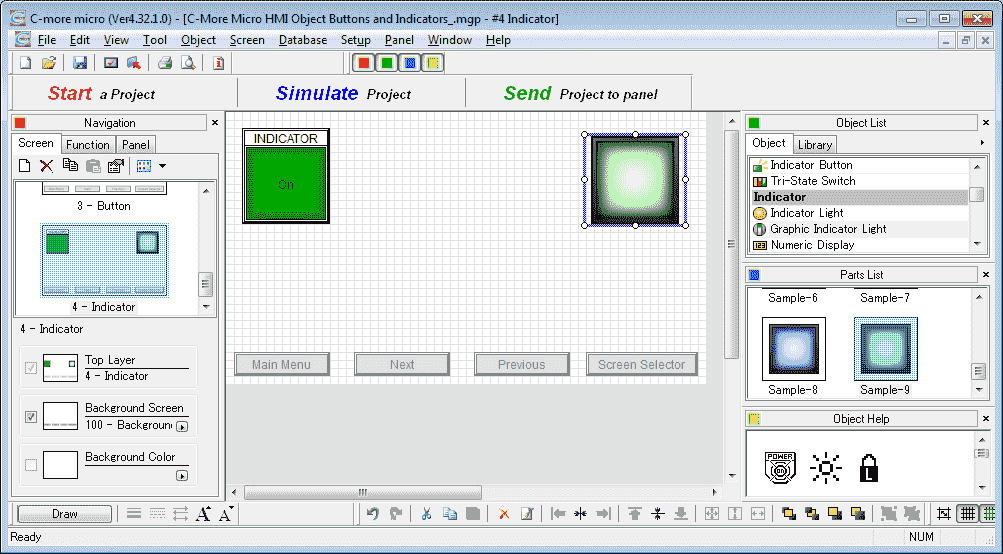
C-More Micro Indicator Light
The Indicator Light object is similar to the ones found on industrial control panels. The Indicator Light can be assigned to a Tag Name and configured to display the status of the Tag Name.
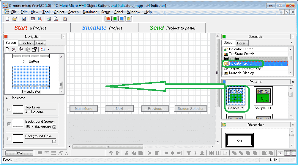
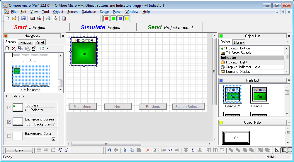
Select screen 4 from the navigation window. Select Indicator Light from the Object List under Indicator. Now click and hold Sample-2 from the parts list and drag onto our screen.
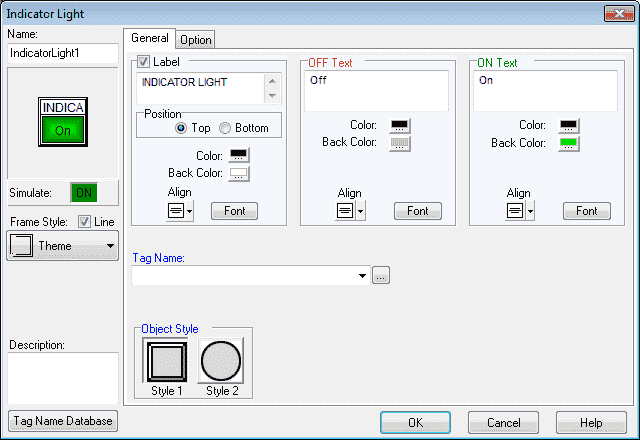
The indicator light window will now appear. The information that you can change is similar to the previous button screens.
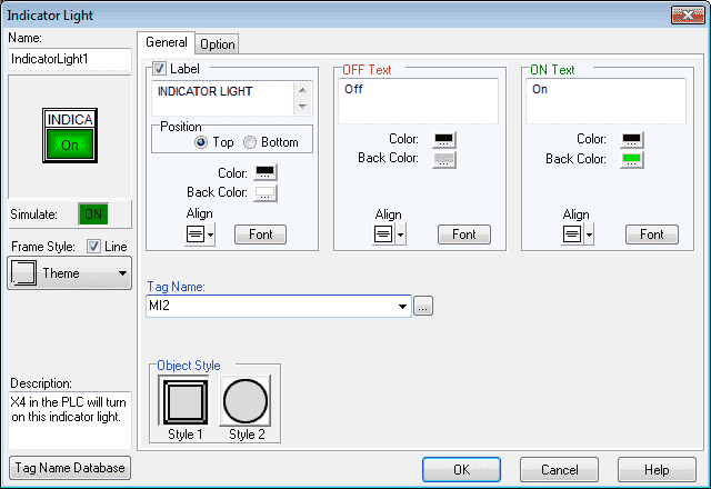
We will change the tag name to MI2. (Modbus Address 10002) Leave all the other selections as their defaults. Select OK.
We can now use the mouse and size and move our indicator light object.
C-More Micro Graphic Indicator Light
The Graphic Indicator Light object provides a selection of pre-designed object Graphics. The operation is similar to the indicator light object.
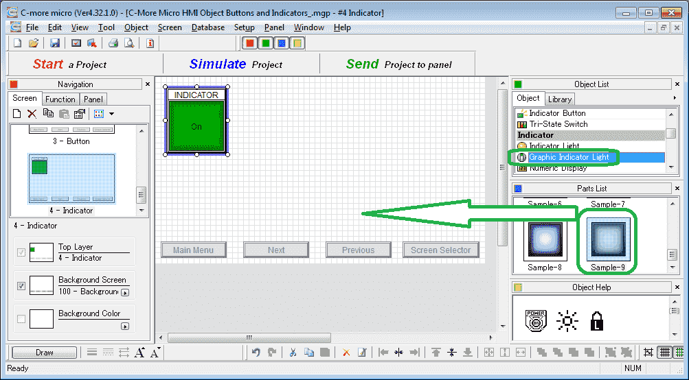
Select Graphic Indicator Light from the Object List under Indicator. Now click and hold Sample-9 from the parts list and drag onto our screen.
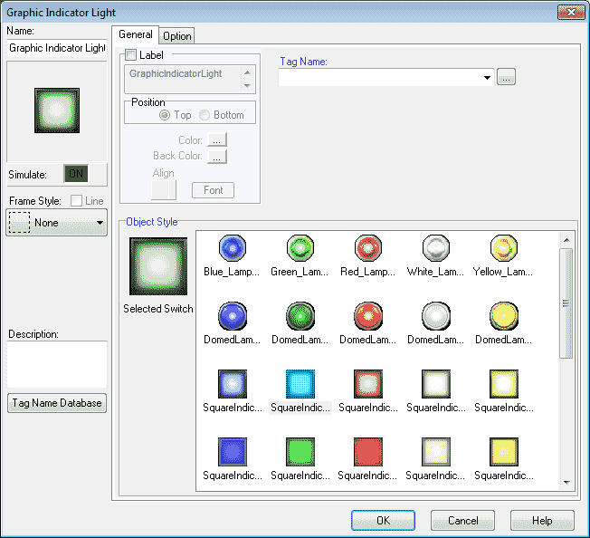
The graphic indicator light window will now be displayed.
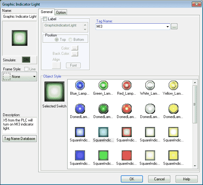
We will change the tag mane to MI3. (Modbus Address 10003) Leave all the other selections as their defaults. Select OK.
We can now use the mouse and size and move our graphic indicator light object.
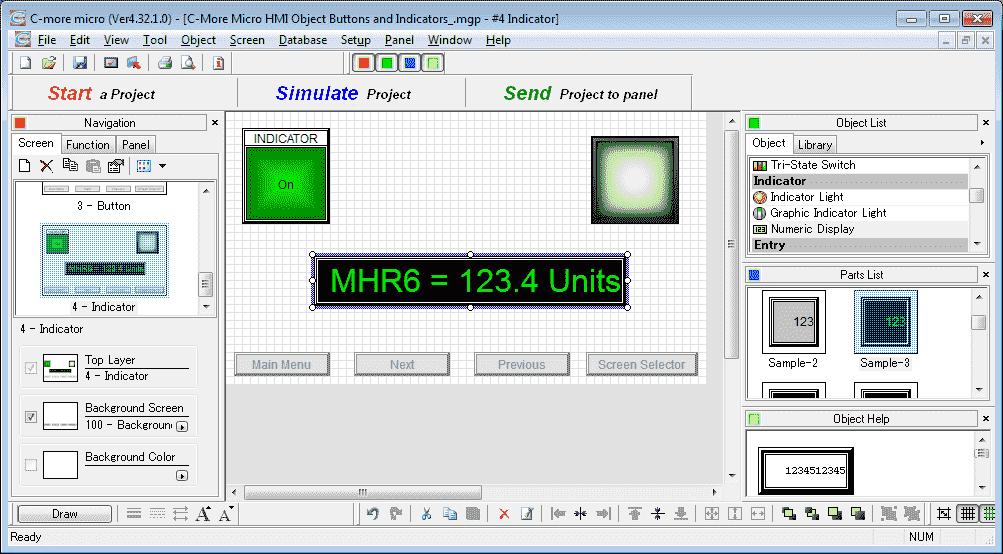
C-More Micro Numeric (number) Display
The Numeric Display consists of a frame that displays the numeric (number) value of an assigned Tag Name.
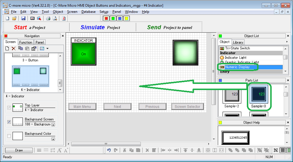
Select Numeric Display from the Object List under Indicator. Now click and hold Sample-3 from the parts list and drag onto our screen.
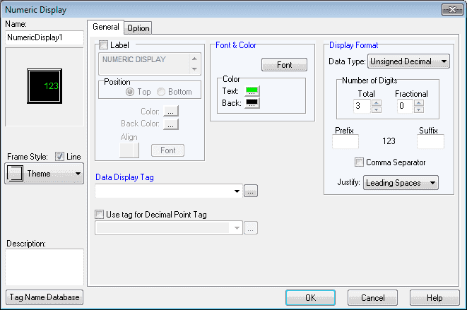
The numeric display window will now be displayed. We have a few different items on this object than the previous ones we have used.
Display Format
Data Type – Click the down arrow to select the type of data that will be displayed. We will use the Unsigned Decimal.
Number of Digits – Total is the maximum for the display tag. We will use 4 as the value.
Fractional – This is the number of decimal places. In our case, we will use 1.
Prefix – This is the text to be displayed before the value. We will use MHR8 to represent the location that we will use in the tag.
The suffix – This is the text to be displayed after the value. It is ideal for the unit of measure that we are displaying in the tag. In our case, we will use the text “Units”.
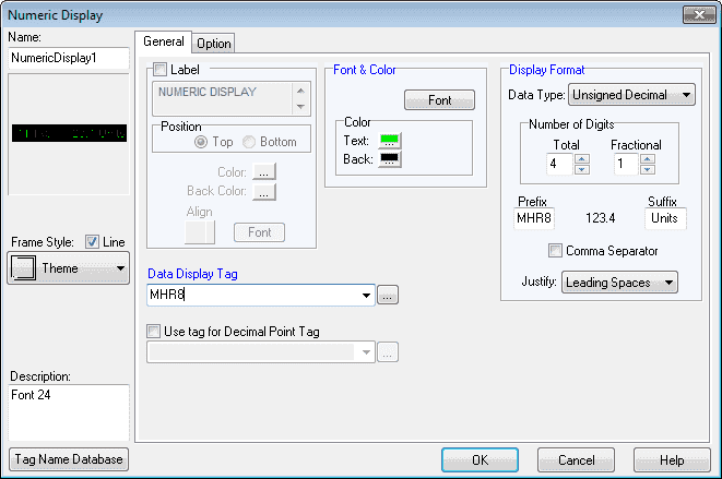
Our Data Display Tag will be MHR8 (Modbus Address 40008). This is an unsigned 16-bit address that will hold a value to be displayed. The font of the text will be set for 24 so we can clearly see the values displayed.
Select OK.
We can now use the mouse and size and move our numeric display object.
PLC Program Additions – C-More Micro Buttons and Indicators
Using the program we previously developed, we will add additional rungs to control the buttons and indicator objects that we have just created.
Download the PLC and C-More Micro program here.
Watch the video below to see the Object Buttons and Indicators in action on our C-More Micro HMI Panel. This will also demonstrate the PLC ladder code for functionality.
C-More Micro Panels from Automation Direct
https://www.automationdirect.com/adc/Shopping/Catalog/HMI_(Human_Machine_Interface)/C-more_Micro_Panels
C-More Micro – Graphic Panel (EA3 Series) User Manual and Quick Start Guides
https://cdn.automationdirect.com/static/manuals/ea3mguserm/ea3mguserm.html
EA3-T4CL C-More Micro Specifications
https://cdn.automationdirect.com/static/specs/ea3t4cl.pdf
C-More Micro Programming Software V4.30
http://support.automationdirect.com/products/cmoremicro.html
This free software will enable you to program all of the C-More Micro HMI units. It includes a simulator for your application.
Next time we will look at the numeric entry objects in the C-More Micro HMI Panel.
Watch on YouTube : C-More Micro HMI Object Buttons and Indicators
If you have any questions or need further information please contact me.
Thank you,
Garry
If you’re like most of my readers, you’re committed to learning about technology. Numbering systems used in PLC’s are not difficult to learn and understand. We will walk through the numbering systems used in PLCs. This includes Bits, Decimal, Hexadecimal, ASCII and Floating Point.
To get this free article, subscribe to my free email newsletter.
Use the information to inform other people how numbering systems work. Sign up now.

The ‘Robust Data Logging for Free’ eBook is also available as a free download. The link is included when you subscribe to ACC Automation.