
We will be using Claude AI Desktop to determine if we can program a PLC using a ladder logic diagram. Has AI learned enough to be useful when programming? We will take the results and enter the AI PLC program into the Do-More Designer PLC Simulator to verify.
Remember that any AI output result needs to be verified to ensure the accuracy of the information. Always test your logic before deploying into the real world. This is part of the commissioning cycle.

Discover the potential of CLAUDE AI in programming a PLC successfully. This post examines the capabilities and limitations of utilizing CLAUDE AI for PLC programming, offering insights into its feasibility and effectiveness. Discover how CLAUDE AI can streamline and automate PLC programming tasks, and determine if it’s the right tool for your industrial automation needs. Get a comprehensive understanding of the benefits and challenges of integrating CLAUDE AI into your PLC programming workflow. Whether you’re an experienced programmer or just starting, this post will help you determine if CLAUDE AI is the solution you’ve been looking for. Continue now to learn more about the future of PLC programming with CLAUDE AI.
Can Claude AI Desktop Program a PLC?
Starting from the beginning, we will ask the question:
Can you program a PLC using ladder logic?
Yes, I can help you with PLC programming using ladder logic! I can:
- Write ladder logic programs for various control applications
- Explain ladder logic concepts like rungs, contacts, coils, timers, and counters
- Convert process descriptions into ladder logic
- Troubleshoot and optimize existing ladder logic code
- Provide diagrams showing the ladder logic structure (though in text format)
- Work with common instructions like normally open/closed contacts, latches, timers (TON, TOF, RTO), counters (CTU, CTD), comparison instructions, and math functions
What I can’t do:
- Actually download or test the program on physical hardware
- Use proprietary PLC programming software (like RSLogix, TIA Portal, etc.)
- Debug hardware-specific issues without detailed information
If you have a specific control problem or application you’d like help with, just describe what you need the PLC to do – like:
- Process to control
- Inputs and outputs
- Desired behavior and sequences
- Any specific PLC brand/model you’re using
I can then write the ladder logic for you and explain how it works. What would you like to program?
AI to Create a Simple Start-Stop Circuit – AI PLC Programming
I want to program a start-stop circuit using a normally open start pushbutton and a normally closed stop pushbutton. This should be done in ladder logic.
I’ll create a basic start-stop circuit for you in ladder logic. This is one of the most fundamental PLC programs!
START-STOP CIRCUIT LADDER LOGIC
================================
Rung 1:
| |
| I:0/0 I:0/1 O:0/0 O:0/0 |
|—-| |——–| |————( )———-| |
| STOP START MOTOR |
| | |
| | O:0/0 |
| |———-| | |
| SEAL-IN |
| |
Legend:
I:0/0 = Stop pushbutton (Normally Closed)
I:0/1 = Start pushbutton (Normally Open)
O:0/0 = Motor output
—-| |—- = Normally Open contact
—-| |—– = Normally Closed contact
——-( )— = Output coil
How It Works:
- At rest: The stop button (NC) is closed, start button is open, and the motor is off.
- Starting: When you press the START button (I:0/1), current flows through the closed STOP contact and the now-closed START contact to energize the MOTOR output (O:0/0).
- Seal-in/Latching: When O:0/0 energizes, the seal-in contact (also O:0/0) closes in parallel with the START button. This maintains the circuit even when you release the START button.
- Stopping: Pressing the STOP button opens the NC contact, breaking the circuit and de-energizing the motor. The seal-in contact also opens, and the circuit resets.
Key Points:
- The STOP button has priority (being in series)
- The seal-in contact creates a “memory” that holds the output on
- This is also called a “latching” circuit
Would you like me to add any features like indicator lights, timers, or additional safety interlocks?
START-STOP CIRCUIT LADDER LOGIC
================================
Rung 1:
| |
| I:0/0 I:0/1 O:0/0 |
|—–| |———-| |———————( )————-|
| STOP | MOTOR |
| | |
| | O:0/0 |
| +—–| | |
| SEAL-IN |
| |
Better explanation of the layout:
- Left vertical line = Power rail
- Right vertical line = Return rail
- I:0/0 (Stop) = Normally Closed contact in series
- I:0/1 (Start) and O:0/0 (Seal-in) = Two parallel branches (the “+” shows the branch point)
- O:0/0 = Motor output coil at the end
Flow:
- Power flows through the NC STOP contact
- Then splits into two parallel paths:
- Through the NO START button, OR
- Through the NO SEAL-IN contact
- If either path is closed, power reaches the MOTOR coil
Would you like me to create this as a visual diagram instead, or is there a specific format you’d prefer for the ladder logic?
Try creating the ladder logic as a visual diagram.
I’ll create a visual ladder logic diagram for you!
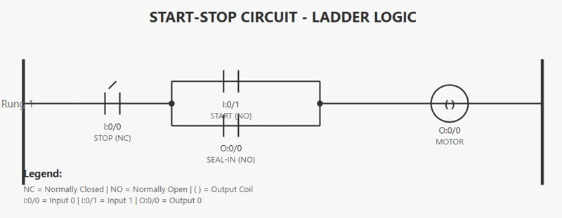
Perfect! Now you can see the ladder logic properly visualized. Here’s how to read it:
Circuit Flow:
- Left power rail → STOP button (NC) → Junction point
- From the junction, power can flow through two parallel paths:
- Upper path: Through START button (NO)
- Lower path: Through SEAL-IN contact (NO)
- Both paths rejoin and continue to the MOTOR output coil → Right power rail
Operation:
- Press START: Closes I:0/1, energizes O:0/0 (motor runs), and the O:0/0 seal-in contact closes to maintain the circuit
- Release START: Motor keeps running because seal-in contact is now closed
- Press STOP: Opens I:0/0, breaking the circuit and stopping the motor
This is the standard self-holding (latching) circuit used in industrial controls. Is this clearer now?
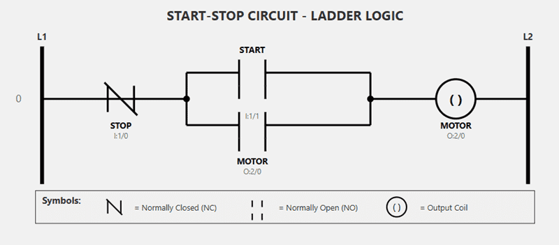
There we go! Now the ladder logic diagram has proper symbols:
Key Features:
- STOP (I:1/0): Normally Closed contact shown with diagonal slash through it
- START (I:1/1): Normally Open contact with visible gap in the middle
- MOTOR Seal-in (O:2/0): Another Normally Open contact in parallel with START
- MOTOR (O:2/0): Output coil shown with the circle and ( ) symbol
- Parallel branches: The START and SEAL-IN contacts are in parallel, so either one can energize the motor
The legend at the bottom shows what each symbol means. Does this look correct now?
Yes, this looks correct now, but the stop pushbutton is wired normally closed, so the ladder symbol should be normally open to work.
You’re absolutely right! That’s a critical point in PLC programming that I got wrong.
When the physical STOP pushbutton is wired normally closed, the ladder logic symbol should be normally open because:
- Physical NC button not pressed = contacts closed = input is ON (1) = NO contact in ladder is CLOSED
- Physical NC button pressed = contacts open = input is OFF (0) = NO contact in ladder OPENS
Let me fix the diagram:
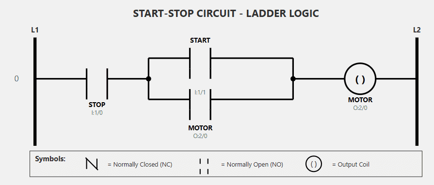
Perfect! Now it’s correct. Thank you for catching that important detail!
The key principle:
- Physical STOP button: Normally Closed (NC) – contacts are closed at rest
- Ladder logic symbol: Normally Open (NO) – because when input I:1/0 is energized (button not pressed), the contact closes
How it works now:
- Normal operation: Physical NC stop button is closed → Input I:1/0 is ON → NO contact in ladder is CLOSED → allows power to flow
- When STOP pressed: Physical NC stop button opens → Input I:1/0 is OFF → NO contact in ladder OPENS → breaks the circuit and stops motor
This is a fundamental concept in PLC programming – you program the opposite of the physical device wiring because you’re reading the input state, not the physical contact state.
Now the circuit will work correctly! Thanks for keeping me accurate.
Correcting AI for the Do-More Designer Programming Software Simulator
Thank you. I am using the Do-More Designer programming software with the simulator. Can you change the input and output addresses?
Absolutely! Do-More Designer uses different addressing conventions. Let me update it to use the proper Do-More addresses:
Perfect! I’ve updated the addresses to Do-More Designer format:
Input Addresses:
- X0 = STOP pushbutton (physical NC button)
- X1 = START pushbutton (physical NO button)
Output Address:
- Y0 = MOTOR output (both the output coil and the seal-in contact)
These are the standard discrete I/O addresses for Do-More Designer. When you program this in the simulator, you’ll be able to:
- Toggle X0 and X1 to simulate pressing the buttons
- Watch Y0 energize when you press START and latch on
- Watch Y0 de-energize when you press STOP
The circuit should work perfectly in the Do-More Designer simulator now!
The ladder diagram is not showing correctly.
Let me redraw the entire diagram cleanly to make sure everything displays correctly:
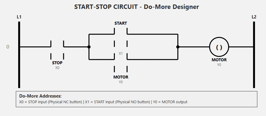
There you go! I’ve redrawn the entire diagram cleanly with the correct Do-More Designer addresses:
Addresses:
- X0 = STOP pushbutton input (NO symbol in ladder because physical button is NC)
- X1 = START pushbutton input (NO symbol)
- Y0 = MOTOR output (used for both the output coil and the seal-in contact)
Is the diagram displaying correctly now?
Yes, thank you. I will now try this in the PLC programming software
Excellent! Good luck with your programming in Do-More Designer.
When you test it in the simulator, remember:
- X0 should be ON initially (since the physical NC stop button is closed at rest)
- Click X1 to simulate pressing START – Y0 should energize and stay on
- Click X0 to simulate pressing STOP – Y0 should de-energize
If you run into any issues or want to add features like timers, indicator lights, or additional controls, feel free to ask. Happy programming! 👍
Programming the AI Ladder Logic Start Stop Circuit – AI PLC Programming
Using our Do-More Designer PLC programming software, we can enter the ladder logic diagram that the AI created. You will see that it provides a comprehensive description of how the program works, along with complete documentation. We can utilize this in our actual program.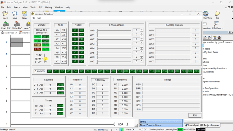
The ladder logic provides the quickest ladder possible. You will see that the Stop input is the first contact. If this contact is not made, the logic will stop scanning and proceed to the next level of logic.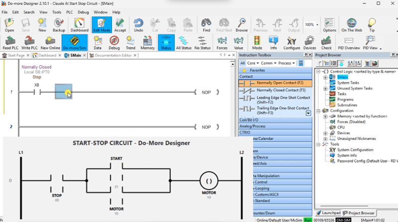
The PLC ladder logic that the Claude AI Desktop application created eventually worked well. The iterations that AI went through to eventually provide a working program also teach those who are not familiar with how ladder logic works and its cyclic nature.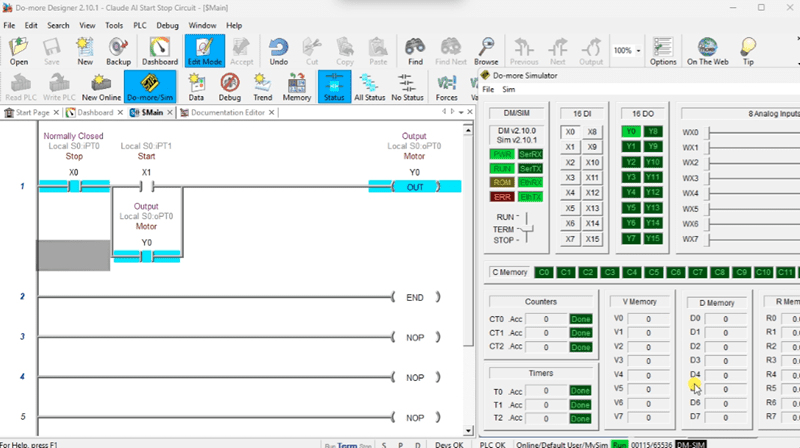
Do-More Series on how to use the Do-More Designer Software with the built-in PLC Simulator. This is a free, entire package that will also communicate through the Ethernet port of the computer running the PLC simulator.
Download the sample program we built with Claude AI Desktop here.
There are many different PLC manufacturers with their own hardware and software. All programmable logic controllers share similar basic features. To learn how to approach learning about basic PLCs, click here. Click here to learn more about how PLC Simulators can be used to help your programming skills, especially with the assistance of AI.
Watch on YouTube: What is PLC Logic in Scan Cycles REALLY Doing?
There are many different PLC manufacturers with other hardware and software. All of the programmable logic controllers have similar basic features. Here is how I would approach learning about basic PLCs.
Once you are familiar with the basics of the PLC, you will then learn specifics for the controller you will be programming.
This is the easiest way to learn about PLC programming.
Here are the controllers that we have covered or are covering at ACC Automation:
LS Electric XGB PLC Series
BRX Do-More Series (Do-More Designer Software + Simulator)
Productivity Series P1000 / P2000
Click PLC Series
Omron CP1H Series
Horner XL4 PLC Series
Arduino Opta PLC
The EasyPLC Software Suite is a comprehensive package that includes PLC, HMI, and machine simulator software. See below to receive 10% off this software. This PLC learning package includes the following:
Easy PLC – PLC Simulation will allow programming in Ladder, Grafcet, Logic Blocks, or Script.
HMI System – Easily create a visual human-machine interface (HMI)
Machine Simulator – A virtual 3D world with real-time graphics and physical properties. PLC programs can be tested using the EasyPLC or through other interfaces. (Modbus RTU, TCP, etc.)
Machine Simulator Lite – Designed to run on Android Devices.
Machine Simulator VR – Virtual Reality comes to life so you can test, train, or practice your PLC programming.
Purchase your copy of this learning package for less than $95 USD for a single computer installation or less than $110 USD to allow access on multiple computers.
Receive 10% off the investment by typing in ACC in the comment section when you order.
Learn PLC programming the easy way. Invest in yourself today.
Examples of PLC program development using the five steps.
Click PLC – Easy Transfer Line Programming – Video
Productivity PLC Simulator – Chain Conveyor MS – Video
Five Steps to PLC Program Development – Die Stamping
PLC Programming Example – Process Mixer
PLC Programming Example – Shift Register (Conveyor Reject)
PLC Programming Example – Paint Spraying
PLC Programming Example – Delay Starting of 7 Motors
PLC Programming Example – Pick and Place
PLC Programming Example – Sorting Station (Shift Register)
PLC Programming Example – Palletizer
If you have any questions or require additional information, please do not hesitate to contact me.
Thank you,
Garry
If you’re like most of my readers, you’re committed to learning about technology. Numbering systems used in PLCs are relatively straightforward to understand. We will walk through the numbering systems used in PLCs. This includes Bits, Decimals, Hexadecimal, ASCII, and Floating Points.
To get this free article, subscribe to my free email newsletter.
Use the information to educate others on how numbering systems work. Sign up now.

The ‘Robust Data Logging for Free’ eBook is also available as a free download. The link is included when you subscribe to ACC Automation.