Compare and math instructions in the Click PLC will allow you to do a number of things. We will use the compare instructions to turn on bits which will indicate production shifts. Using the math instruction we will convert the number of units made to a weight.
Previously in this series, we have discussed:
System Hardware – Video
Installing the Software – Video
Establish Communication – Video
Numbering System and Addressing – Video
Timers and Counters
– Counter Video
– Timer Video
The programming software and manuals can be downloaded from the Automation Direct website free of charge.
Compare Contact – Click Compare and Math Instructions
The Click PLC uses contacts in order to compare the expressions. The resulting logic can be used to trigger an output. (Internal or External) You can also use multiple compares on the same rung of logic.
The following logic can be used:
Equal To Keyboard Shortcut ‘=’ Ex. A = B
Not Equal To Keyboard Shortcut ‘!’ Ex. A ! B
Greater Than Keyboard Shortcut ‘>’ Ex. A > B
Less Than Keyboard Shortcut ‘<’ Ex. A < B
Greater Than or Equal No Keyboard Shortcut Ex. A >= B
Less Than or Equal No Keyboard Shortcut Ex. A <= B
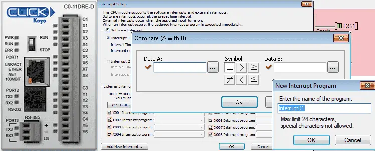
Once you call up any of the above contacts a dialog box will then open. This will allow you to now enter the two memory locations that will be compared. You can use the address picker or enter the values manually.
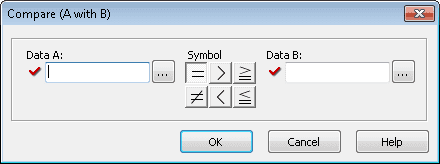
Data A – First Data Memory or Constant to be Compared in the Click Program
Data B – Second Data Memory or Constant to be Compared in the Click Program
Symbol – This is the mathematical operator applied to Data A and Data B
Compare Contact Click Program Example
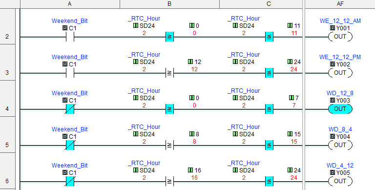
Let’s look at an example. Our factory has 5 different shifts.
Weekdays Midnight – 12 am to 8 am
Weekdays Days – 8 am to 4 pm
Weekdays Afternoon – 4 pm to 12 am
Weekend Morning – 12 am to 12 pm
Weekend Afternoon – 12 pm to 12 am
We will turn on the outputs indicating which shift we are currently in by looking at the real-time clock and using the compare instructions.
The first rung will determine if it is the weekend or not. Using the day of the week bit we look to see if it is either a 1 (Sunday) or 7 (Saturday).
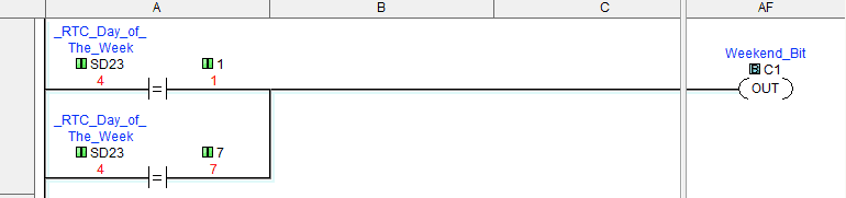
The next five rungs will then determine the shift that we are on. We use the above weekend bit as well as the hour of the day. (0 – 24 hours)
Math Instruction – Click Compare and Math Instructions
The math instruction in the Click solves equations that are entered as a formula on the screen. This is solved during the execution of the program. If floating-point is used in any operation then the formula solves the equation using floating-point. The solution is stored in the data format selected for the result.
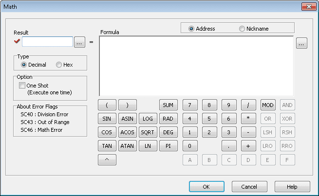
Result – Assigns a memory location for the result of the operation.
Type – This is selecting between Decimal and Hexadecimal numbering systems.
One Shot – Will only solve the operation one for a transition from off to on for the rung condition.
Error Flags – These flags will be set each time the math instruction is executed.
Address or Nickname – You can address the data in the formula by actual address or nicknames that you have assigned.
Formula – This is where you create the equations to solve. You can type in the formula and use the keypad below for the operations.
Note: Look under the help file in the software for more information on the order of operations etc.
Math Instruction Click Program Example
Let’s now look at an example. We will count the number of units being made in our factory. We will use a timed interrupt at 2 seconds with the condition that input coming from a sensor (X1) must be on to count. We will also calculate the total weight of the amount made by multiplying the unit count by 3.14. This will convert the units to a weight. (Kg)
The first thing that we will do is make an interrupt routine. We can do this in several different ways.
Right-click the ‘Interrupt Program’ under the navigation window will call up the ‘Add New Interrupt Program’.
Or go to the main menu Program | Add New Interrupt Program
Or hit Ctrl + I
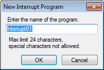
Name the interrupt ‘Unit Count Interrupt’. You will now get a program quick guide to explain writing interrupt routines.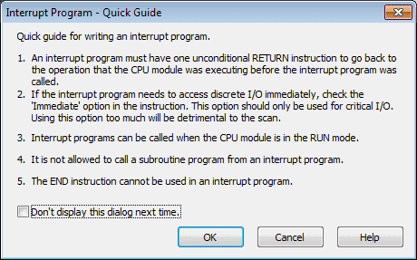
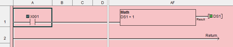
We can now enter our interrupt routine. The two rung routine will use the math instruction to add 1 to memory location DS1 and store the result at DS1. All interrupt routines must have a ‘Return’ statement to signify the end of the routine and return to the spot in the program that was interrupted.
The last thing that we need to do with our interrupt routine is the setup. This is where we will determine if it is a timed or event-driven interrupt and set the parameters. Under the navigation window, you can right-click our interrupt routine ‘Unit Count Interrupt’ and select ‘Interrupt Setup…’ You can also use the menus to get to the interrupt setup. Setup | Interrupt Setup…
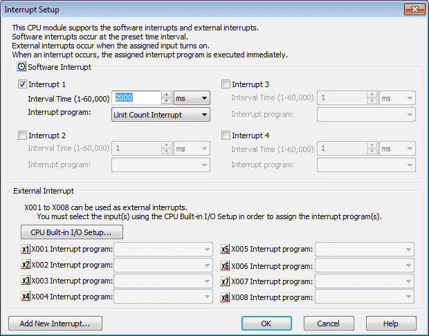
For our program, we will select Interrupt 1 under the Software Interrupt section. We will set the Interval Time for 2000 ms. (2 seconds) There is a drop-down menu for the Interrupt program option. Since we have programmed only the one interrupt it will be the only one that we can select.
External interrupts are always on the CPU built-in I/O. In order to set them up to run interrupt routines, you first must tell the CPU that they will be used for interrupts. Select the ‘CPU Built-in I/O Setup’
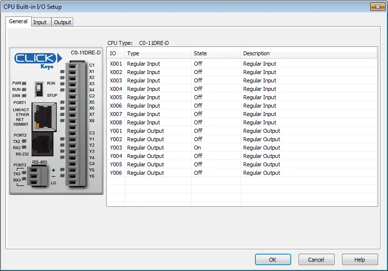
From this window select the Input tab at the top.
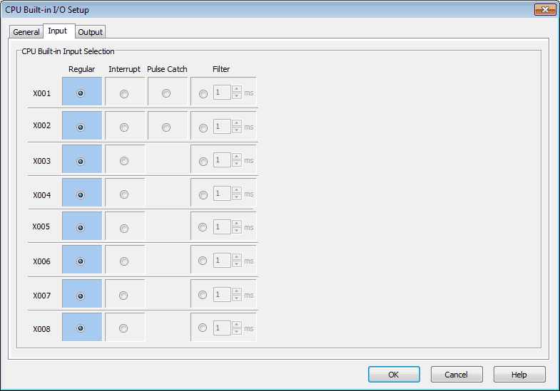
We can now select how each of the inputs will function.
Regular – Normal operation on the inputs
Interrupt – Trigger an interrupt during the transition from off to on
Pulse Catch – This will allow the CPU to see an input that is faster than the scan time. It will hold the signal until the CPU detects it.
Filter – We can set the filter for the input from 1 to 99 ms. This will allow the CPU to not record any bounces on the input signal. If you are using the input in your program to trigger a counter and you get multiple counts for each input signal then the filter would be used to eliminate the extra counts.
The last thing to do in our program is add the math instruction to convert our counts to weight.
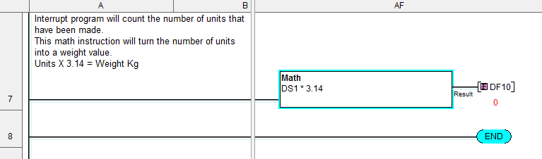
Our result will be placed in memory location DF10. Notice that the math instruction in the Click will automatically convert our integer count value (DS1) to a floating-point value (DF10).
Next time we will look at program control instructions.
Watch on YouTube: Click PLC Compare and Math Instructions
If you have any questions or need further information please contact me.
Thank you,
Garry
If you’re like most of my readers, you’re committed to learning about technology. Numbering systems used in PLC’s are not difficult to learn and understand. We will walk through the numbering systems used in PLCs. This includes Bits, Decimal, Hexadecimal, ASCII and Floating Point.
To get this free article, subscribe to my free email newsletter.
Use the information to inform other people how numbering systems work. Sign up now.

The ‘Robust Data Logging for Free’ eBook is also available as a free download. The link is included when you subscribe to ACC Automation.