The program control instructions will allow us to specify what parts of the logic get solved and when this happens. This will control how the PLC will scan and solve your logic in your program.
Previously in this series we have discussed:
System Hardware – Video
Installing the Software – Video
Establish Communication – Video
Numbering System and Addressing – Video
Timers and Counters
– Counter Video
– Timer Video
Compare and Math Instructions – Video
The programming software and manuals can be downloaded from the Automation Direct website free of charge.
Click PLC Program Control Instructions
Program control (flow) instructions in the Click PLC will utilize interrupts and subroutines. In the last post on Click PLC Compare and Math Instructions, we discussed interrupts. They can be timed or event (Built-in inputs on the CPU.) When the interrupt happens it will immediately go and solve the logic in the interrupt and then return to the instruction following the location that it was called. This can and will happen at any time throughout the scan of the PLC.
Interrupt – Click Program Control
Let’s take a look at an example of an interrupt. We will flash an output on for 3 seconds and off for 3 seconds. A review of entering interrupts can be found in our last post. Click PLC Compare and Math Instructions
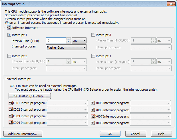
We will be using software interrupt 1. The interval time will be 3 seconds and it will call up our interrupt routine called ‘Flasher 3sec’.
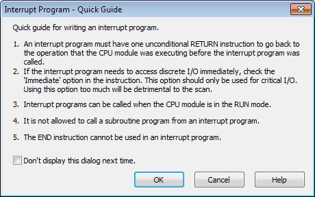
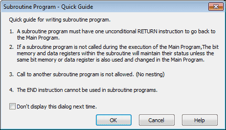
Here is the interrupt program quick guide that will be displayed as a reminder of the way in which interrupts are used.
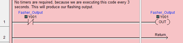
The code that we use for the flasher is just a normally closed contact going to the output of the same contact. Since this logic will only execute once every three seconds, it will alternate the output on and off.
Subroutines – Click Program Control
Subroutines are blocks of code that will get executed when they are called from the main program. This differs from the interrupt because with subroutines we have complete control of when it will be executed in relation to the main program. In the Click PLC, we can have 986 subroutines. This means that we will have 986 calls or more in the main program to execute the code in the subroutine. We cannot have nested subroutines. This means that each subroutine must return to the main program. It cannot call another subroutine.
When a Subroutine program is not called during a scan of the main program the memory bits and data registers within the subroutine will maintain their status unless some other part of the program changes their status or data.
The purpose of subroutines is to organize your code into manageable pieces. These pieces can also be re-usable. The readability of your PLC program improves when using subroutines because you are just looking at smaller pieces of code. The alternative would be all of the rungs in just the main program. This is hard to read and especially troubleshoot when things are not working.
Here is what happens when scanning the program:
- Main program logic is scanned/solved until it reaches a subroutine call
- Subroutines logic is scanned /solved until it reaches the return statement
- The main program logic continues to scan/solve with the rung that follows the subroutine call
- This will continue until the End statement is read which will then complete the rest of the PLC scan and start again
Note: Interrupt routines can happen at any time and the logic will continue to be solved after the logic of the interrupt is executed.
Subroutine Example – Click Program Control
Let’s look at an example. We will have two motors that need to be controlled. Each motor will have a start, stop and jog push buttons.
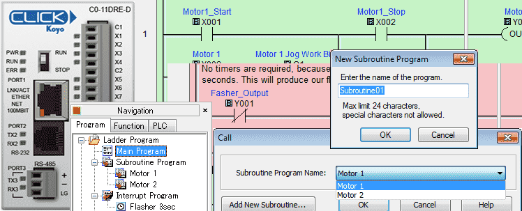
The first thing that we will do is make our subroutines. (Motor 1 and Motor 2)
To make a new subroutine, you can do one of the following.
Main Menu – Program | Add new subroutine program…
Keyboard Shortcut – Control ‘U’ – CTRL+ U
Navigation Window – Right Click on ‘Subroutine Program’ and select ‘Add New Subroutine Program CTRL+ U’
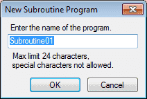
Enter the name of the subroutine. (Motor 1) Hit OK. The subroutine program quick guide will now appear. It will remind us of how to use the subroutine program. Hit OK.
Under the navigation window, we will now see our subroutine Motor 1. Double click on it and we will enter the following code for motor 1.
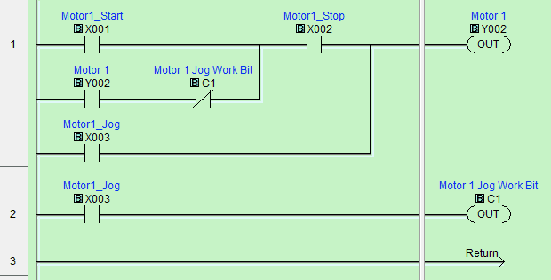
You will notice that the subroutine background defaults to green. The interrupt background is red. This can be changed by going to the following menu selection. Main Menu – Setup | Software Setup…
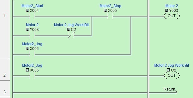
Now repeat the steps above for another subroutine for motor 2. It should look like the following:
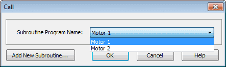
Under the navigation window, double-click the main program. We can now call our subroutines that we have just made in the main program so that they will execute. We will use unconditional rungs and the ‘Call’ instruction. Enter the following on the main program.
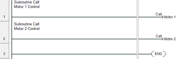
Note: Since we created our subroutines before using the call instruction they are available in the pull down menu of the instruction. We could also have added a new subroutine by this same instruction.
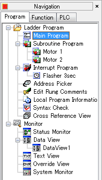
Looking at the navigation window we can see our two subroutines and interrupt the program.
Download the Click PLC Program Control sample PLC program.
Controlling our program is easy with subroutines and interrupts. The advantage is that our program will also be easier to read, understand and troubleshoot.
Next time we will look at shift register instruction.
Watch on YouTube: Click PLC Program Control Instructions
If you have any questions or need further information please contact me.
Thank you,
Garry
If you’re like most of my readers, you’re committed to learning about technology. Numbering systems used in PLCs are not difficult to learn and understand. We will walk through the numbering systems used in PLCs. This includes Bits, Decimal, Hexadecimal, ASCII, and Floating Point.
To get this free article, subscribe to my free email newsletter.
Use the information to inform other people how numbering systems work. Sign up now.

The ‘Robust Data Logging for Free’ eBook is also available as a free download. The link is included when you subscribe to ACC Automation.