Continuing our series, we will now look at timers and counters and how they are used in the Click PLC. Previously we have discussed:
System Hardware – Video
Installing the Software – Video
Establish Communication – Video
Numbering System and Addressing – Video
The programming software and manuals can be downloaded from the Automation Direct website free of charge.
Click PLC TIMERS
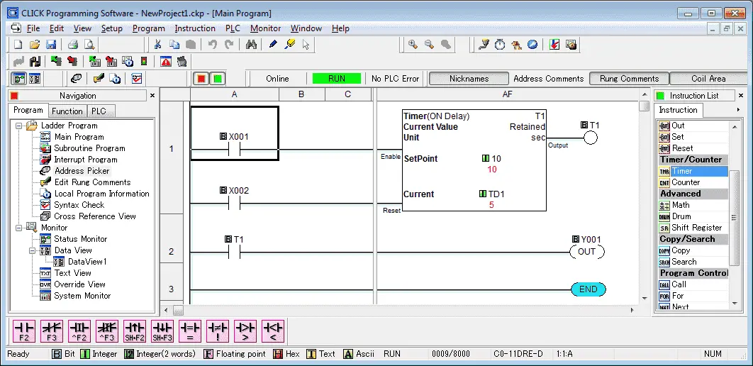
The Click PLC can have 500 unique timers in the program. (T1 to T500) There is only one timer (TMR) instruction in the PLC, but you can adapt it to handle any timing application that you may need.

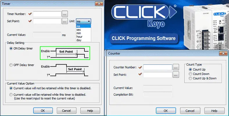
Timer Number – This is a number from T1 to T500 to specify the timer.
Set Point – This is an integer (16 Bit) that represents the set point of the timer. The values are from 1 to 9999. This can also be a memory location so that the timer set value can change during program execution.
Unit – This can be set for milliseconds (ms), seconds (sec), minutes (min), hours (hour) or days (day).
Current Value – This is the location in which you can see use the current value. It is automatically assigned by the timer number. Example: T1 = TD1, T2 = TD2, etc.
Delay Setting – The delay setting is used to determine if you would like an ON Delay timer or an OFF Delay timer. You will see in the diagram above the timing chart is displayed to show you the difference.
Current Value Option – This is used to determine if the timer will be reset with the enabling rung or it will require a separate reset rung.
Applications that use timers always start with a timing chart. This is the secret to using timers in your programs. Additional information on timers can be found at the following post. The Secret Of Using Timers
Timers in the Click PLC by default are not memory retentive. However, this can be changed. See Memory Retentive heading below.
The Click PLC can come with a real time clock. To set the clock in the PLC to match the PC (computer), call up the following Calendar/Clock Setup window. When online select the following from the top menu. PLC | Calendar/Clock Setup
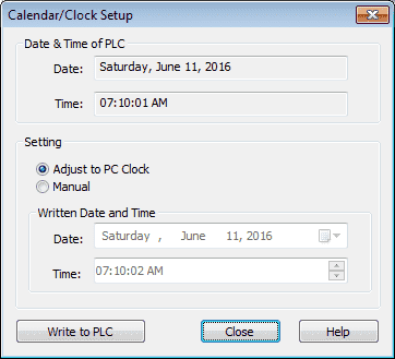
You will notice that it will display both the date and time in the PLC as well as the computer. Under setting, you can manually enter a date and time or select adjust to PC Clock. Then hit the Write to PLC button at the bottom of the window. Your date and time will now be synced with the PLC.
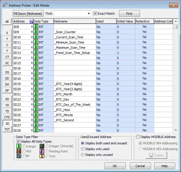
The real-time clock is located in the SD area of memory in the PLC. Use the Address Picker to display the real-time clock from SD19 to SD26.
Additional Information on the real-time clock of the Click PLC can be found here:
Real-Time Clock (RTC) – Video
Watch on YouTube: Click PLC Timers
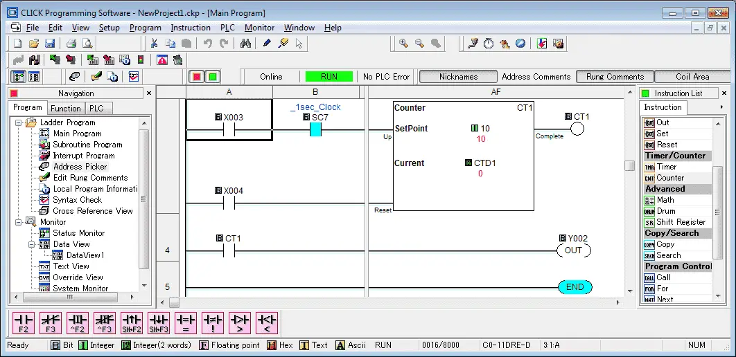
Click PLC COUNTERS
The Click PLC can have 250 unique counters in the program. (CT1 to CT250) There is only one counter (CNT) instruction in the PLC, but you can adapt it to handle any counting application that you may need.
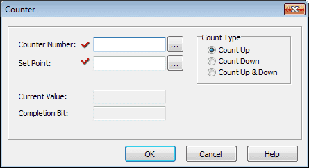
Counter Number – This is a number from CT1 to CT250 to specify the counter.
Set Point – This is an integer (16 Bit) or double integer that represents the set point of the counter. The values are from 1 to 9999 for and integer and 1 to 999999999 for a double integer. This can also be a memory location (I or I2) so that the counter set value can change during program execution.
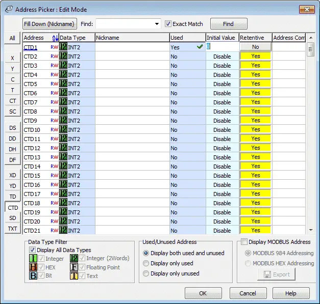
Current Value – This is the location in which you can see use the current value. It is automatically assigned by the counter number. Example: CT1 = CTD1, CT2 = CTD2, etc.
Completion Bit – This is the bit that will turn on when the counter has completed. It is set automatically by the software and is the same as the counter number.
Count Type – This can be one of the three types of counter. Count UP – Will increment up to the set point. Count Down – Will decrement down from the set point to zero. Count Up & Down – Will increment or decrement the current count value. The output will turn on when the set value is reached.
Note: All of the counters will have a reset input. This will reset the current value to zero for the Count Up and Count Up & Down modes. The Count Down will reset the current value to the set value.
Applications that use counters always start with a timing chart. This is the secret to using counters in your programs. Additional information on counters can be found at the following post. The Secret Of Using Counters
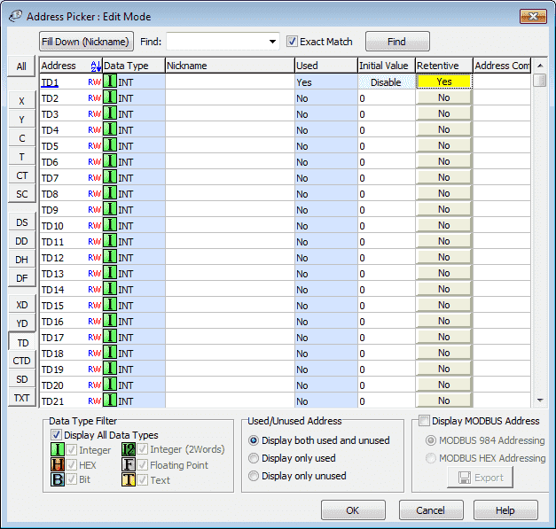
Memory Retentive
Memory retentive means that when power is removed from the PLC or it switches from run to stop mode, the current value is not lost. (Reset) The default for timers is non-memory retentive. The counters are memory retentive. In the Click PLC we can choose this setting along with the initial (Reset) values.
Next time we will look at compare and math instructions.
Watch on YouTube : Click PLC Counters
If you have any questions or need further information please contact me.
Thank you,
Garry
If you’re like most of my readers, you’re committed to learning about technology. Numbering systems used in PLC’s are not difficult to learn and understand. We will walk through the numbering systems used in PLCs. This includes Bits, Decimal, Hexadecimal, ASCII and Floating Point.
To get this free article, subscribe to my free email newsletter.
Use the information to inform other people how numbering systems work. Sign up now.

The ‘Robust Data Logging for Free’ eBook is also available as a free download. The link is included when you subscribe to ACC Automation.