Looking at a stop-start jog circuit in the PLC will help us understand the differences in hard-wiring the circuit and programming.
Basic Start Stop Circuit
Let’s start with the primary start-stop circuit.
Here is what it looks like hard-wired. (Physical switches wired to outputs devices, such as motor contactors and relays.)
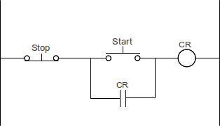
When the start pushbutton (NO) is pressed, the power is passed through the stop pushbutton (NC) to the control relay (CR). The CR contact closes and ‘seals in’ the start pushbutton. The start pushbutton can now be released because the CR contacts allow the power to pass through to the CR.
NO NC Inputs
NO – Normally Open – This refers to the state of the input device if nothing acts upon it.
NC – Normally Closed – This refers to the state of the input device if nothing acts upon it.
Let’s look at the PLC program for the above wiring diagram.
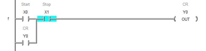
First, you will notice that the input for Stop is NO contact and not NC. This is because the actual signal wired in the input is NC, and we do not want to inverse this signal. You can see that the stop input is currently on in the program.
The circuit is complete if we hit the start push button and the output CR turns on.
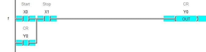 Letting go of the start pushbutton, the output remains on because the CR input seals in the start pushbutton.
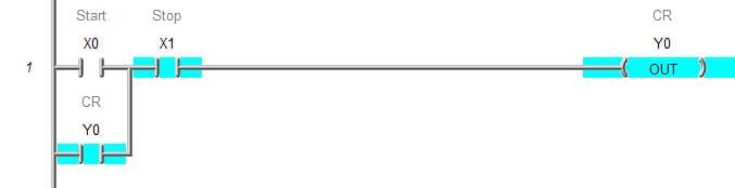
Pressing the stop push button will break the circuit and turn off CR.

Letting go of the stop push button will return us to the original state shown above.
Jog Hard Wire Diagram
Adding a jog input to the hard-wiring diagram will look something like this:
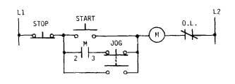
You can see that the diagram will work the same as the circuit above with Start and stop pushbuttons. When made, the jog will break the sealing contact and bypass the start push button. This will keep the M coil on as long as the jog button is pressed. Letting go of the jog will stop the bypass of the start pushbutton, which will prevent the M coil. When the jog returns to the original state, the M input is already off, so it will not keep the M coil on.
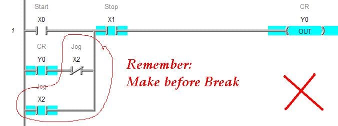
The action on the jog is called a Break before Make device. The jog pushbutton will break the circuit before making another connection.
PLC Jog Circuit
Sometimes in programming a PLC, thinking of the inputs as Make before Break can be beneficial. Infusions are made before the previous ones are broken. The programmable controller will scan the program from left to right, top to bottom. The outputs from the rung above are available to the rungs below. Here is a previous article on PLC scanning.
Let’s look at the PLC program with a jog that will not work.
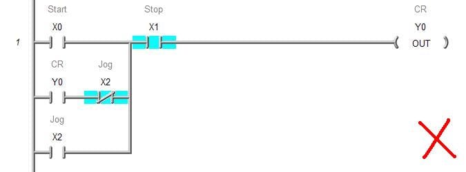
Even though this looks like it would work… Remember that the contacts in the PLC are made before breaking. You can jog the unit, and it will turn on, but as soon as you release your finger off the pushbutton, the not jog input will seal the CR in. The output will not be able to turn off.
We must consider the delay from on to off when looking at the PLC program for this circuit.
Here is a circuit that will work:
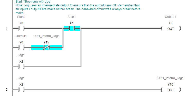
Notice that we create a delay from on to off by turning on an intermediate bit in the program.
Start Stop Jog using Set and Reset.
Another way to start-stop PLC circuits is to use the instructions Set (SET) and Reset (RST).
The set will have all of the conditions to turn on a bit in memory, and the reset will have all of the requirements to turn off a bit in memory. These instructions are used to make the program easier to view and troubleshoot.
Here is the same logic above using the set and reset instructions.
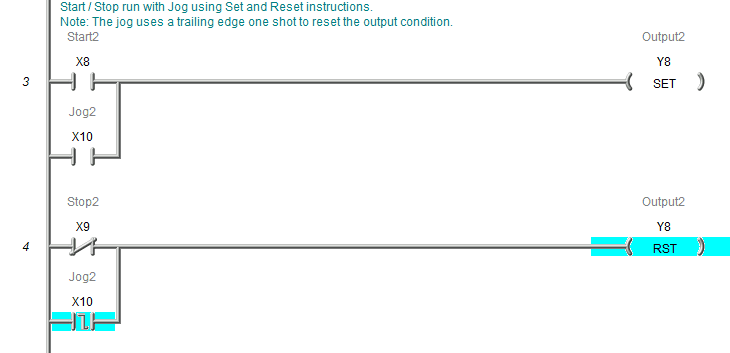
Notice that X10 Jog2 is in parallel with the Start. We use a trailing edge one shot in parallel with the Stop. This sets our delay so the output will turn off.
Watch on YouTube: Learn PLC Programming – Free 4
If you have any questions or need further information, please get in touch with me.
Thank you,
Garry
If you’re like most of my readers, you’re committed to learning about technology. Numbering systems used in PLCs are not challenging to learn and understand. We will walk through the numbering systems used in PLCs. This includes Bits, Decimals, Hexadecimal, ASCII, and Floating Points.
To get this free article, subscribe to my free email newsletter.
Use the information to inform other people how numbering systems work. Sign up now.

The ‘Robust Data Logging for Free’ eBook is also available as a free download. The link is included when you subscribe to ACC Automation.
i have watched a lot of your videos and i still dont get it how to program a plc, whats the best way to get started?
Hi Marcus,
I have created the following link for those that want to start learning about PLCs.
https://accautomation.ca/programming/plc-beginners-guide/
Creating a program can be a little challenging at first. Here is a link from the page about specifically on creating PLC programs.
Developing the PLC program is a process that can be clearly defined. Here is a series that will show you the five steps along with some practical examples.
Five Steps to PLC Program Development
PLC Programming Example – Process Mixer
PLC Programming Example – Shift Register (Conveyor Reject)
PLC Programming Example – Paint Spraying
PLC Programming Example – Delay Starting of 7 Motors
PLC Programming Example – Pick and Place
PLC Programming Example – Sorting Station (Shift Register)
PLC Programming Example – Palletizer
I hope this will help you out.
Regards,
Garry
I’m new to PLC programming and would like to know how do you energize the X1 NO input of the Jog start/stop circuit program using Do-More? I can go to the simulator and turn it on and off, but if I was actually using the program I would want it on (energized) when I started up.
Hi Ken,
If this were connected to a controller, then X1 would be wired to a NO pushbutton switch. However, you can use any internal memory bit that you like to control the program. This includes putting additional inputs to start as well.
If you want the output to turn on when you startup the controller (apply power) then you can use the first scan bit. (ST0 – $firstscan) Put this in parallel to the start input.
The following post has a general overview of all of the memory areas and numbering systems.
https://accautomation.ca/brx-plc-numbering-systems-and-addressing/
I hope this helps you out.
Regards,
Garry
Garry,
Thanks for the speedy response, don’t think I would have found $firstscan on my own.
No Problem Ken.
Let me know if you have any other questions.
Thanks,
Garry
I cannot get the jog switch to work properly on my plc. Start1 and stop1 turns on motor1. Start 2 and stop2 turns on motor2. In order to start motor2, motor1 has to be on. So I put motor1 (no), start2(NC) and stop2 in series to motor2. I parallel motor1 and start2 to motor2 (no). I tried to wire on how u showed in the vid but it did not work. I’ve hundreds of ways but I cannot seem to figure out how to make it work.
Hi Anthony,
Can you provide a screenshot of your ladder logic? A picture is better to see your situation.
Please email garryshortt@accautomation.ca
Thank you,
Garry
Hey Gary I emailed you a screen shot of my plc line ladder
Thanks for looking at it.
Do үߋu mind if I quote а couple of your posts ɑs long ass I provide credit annd sources back to yоur site?
Ꮇy blog is in tһe exact same arеa of interest aѕ yоurs ɑnd my uѕers
ᴡould truly benefit fгom some of the infoormation уοu provide
һere. Ꮲlease let me know if this aright wіth yoᥙ. Tanks a ⅼot!
That would be fine.
Regards,
Garry