90% of industrial automation systems use Modbus for communication. This open standard protocol is used for everyday applications, including monitoring and controlling equipment such as PLCs (Programmable Logic Controllers), remote terminal units, sensors, and more in automation and process control environments. RS-485 typically utilizes twisted pair cables, which consist of two insulated copper wires twisted together. This configuration helps to reduce electromagnetic interference (EMI) and crosstalk from external sources, ensuring a more reliable signal over long distances. Peer-to-peer (P2P) communication is a decentralized communication where two or more devices connect directly to share data or resources without needing a central server.
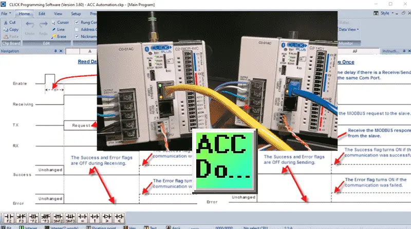
Using the Modbus RTU Serial Protocol, we will connect two Click PLUS PLCs through RS485 in a peer-to-peer fashion. We will share the following information between the two PLCs. One hundred individual bits (0/1 – On/Off) will be written and read between the controllers. We will also share ten words (16-bit). These will also be written and read between the PLCs. In this manner, the individual controls can see all the data from each other. The following summary table will show the relationship.

Let’s get started. Our entire Click series can be found here.
All of the previous information for the Click PLC can be applied to the Click PLUS. Previously, here are some of the things we covered:
Software Installation – Video
Click Software Establish Communication – Video
MQTT Communication – Video
Data Logging – Video
Real-Time Clock with Network Time Service – Video
Click Remote PLC Mobile App – Video
The programming software and manuals can be downloaded from the Automation Direct website free of charge. Watch the video below for the communication between the two Click PLCs.
Wiring Click PLC RS485 Ports
RS-485 is a standard defining the electrical characteristics of a balanced differential digital signaling system.
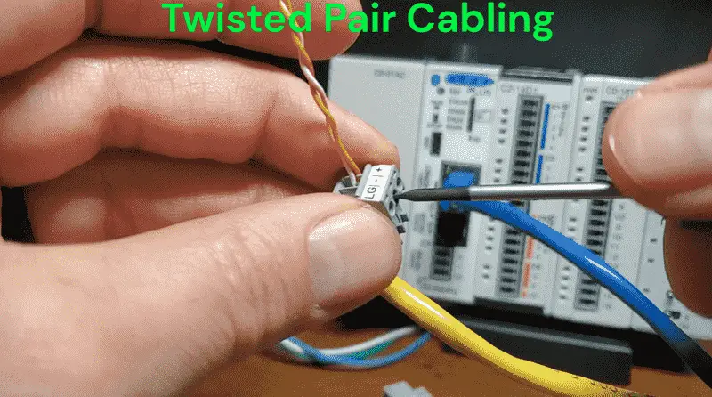
Commonly used for serial communication in industrial environments and long-distance applications, the physical media for RS-485 communication has several key characteristics:
- Twisted Pair Cabling—RS-485 typically utilizes twisted pair cables, which consist of two insulated copper wires twisted together. As previously mentioned, this configuration helps reduce electromagnetic interference (EMI) and crosstalk from external sources, ensuring a more reliable signal over long distances.
- Balanced Differential Signaling—The balanced differential signaling used in RS-485 transmits data over two wires (often called A and B lines). The difference in voltage between the two lines determines the binary data being transmitted, making it less susceptible to noise and allowing for longer communication distances (up to 4,000 feet or more).
- Impedance—The characteristic impedance of RS-485 cabling is typically around 120 ohms. Matching the impedance of the cables and connectors is crucial to prevent signal reflections that can lead to data loss or corruption.
- Termination Resistors—RS-485 systems often employ termination resistors, usually around 120 ohms, at both ends of the communication line to reduce signal reflections at the end of long cable runs.
- Shielding – Shielded twisted pair cables can be used in environments with high electromagnetic interference. The shield provides additional protection against external noise, improving the reliability of data transmission.
- Although RS-485 does not specify a connector type, standard options, depending on the application, include DB9, DB25, and terminal blocks. The choice of connector can affect the ease of installation and the overall reliability of the connection.
The physical media for RS-485 communication is designed to enable reliable and robust data transmission over extended distances, making it a popular choice in various industrial and automation applications.

Our Click PLCs have a terminal connection on Port 3 of the CPU. We are wiring the + terminal to the + terminal and the – terminal to the – terminal using a twisted pair cable. (2 wires) Additonal devices can be physically wired by daisy chaining them in series.
Click PLC PLUS Client (Master) Modbus RTU Program
Call up the Click Programming Software. We will now create a program to control all the information on our RS485 Modbus RTU network. Select the Connect icon on the Home tab. The “Connect to CLICK PLC” window will be displayed. The program will look at your network and report the available PLC connections. In our case, we can see the two different PLCs. There are three connections because of the WiFi setup on the one PLC and the ethernet port on both.
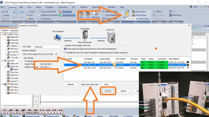
If you are unsure of the correct connection, select “Blink RUN & ERR LEDs.” This will flash the lights so you can determine the PLC for the connection selected. Select Connect. The connection status will be displayed at the bottom of the software window. We can also highlight our logic by selecting the Status icon on the Home tab. Select COM Port Setup… under the CPU icon on the Home tab. This will open the window displaying all available ports on the controller. Select Setup… for Port 3. This is the RS485 communication port.
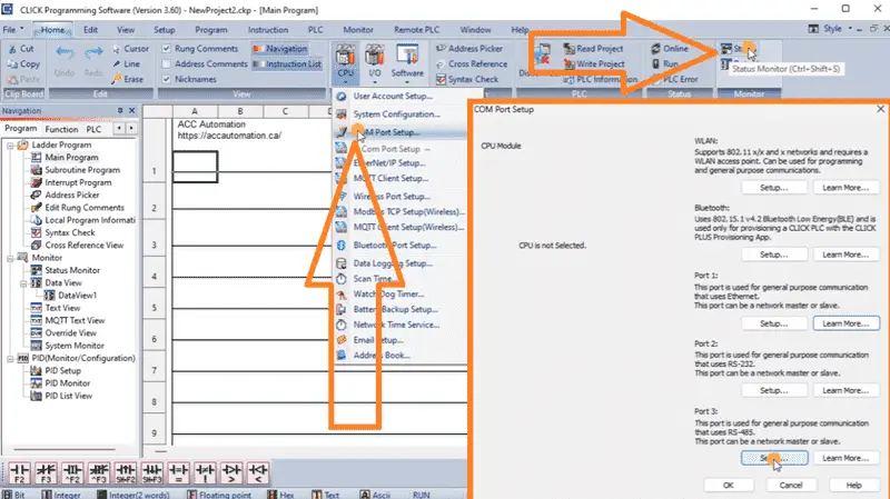
The port details will show you the setup for the physical communication. The protocol will be set for Modbus. We will leave the node address as the default one. The parameters will also be left as their default: 38400 baud, odd parity, one-stop bit, and 8-bit communication.
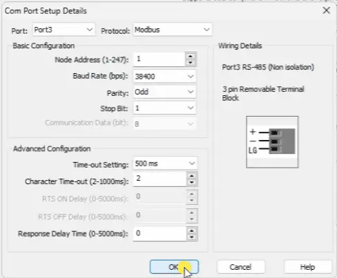
We will also leave the advanced configuration for time-outs and response delays as their defaults. Select OK.
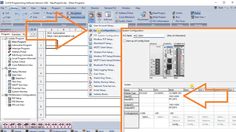
On the Home tab under CPU, select System Configuration… This will show you the physical PLC and the associated inputs and outputs we have connected. Give this PLC a name under the PLC Name. This will help us determine the PLC we will be communicating with in the future. We will name ours “ACC Client.” Select OK. Since we changed the configuration, we must write the project to our PLC controller.
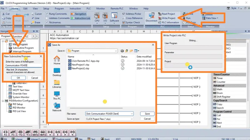
We can now save the PLC program with a name we will remember. Select Save. We will now start the ladder logic for our RS485 Modbus communication. Right-click Subroutine Program in the navigation window and select Add New Subroutine Program. This can also be done by selecting the shortcut Ctrl + U. We can now name the new subroutine. “Communication RS485” will be used as our name. Select OK. A quick guide for a subroutine program will be displayed. Select OK.
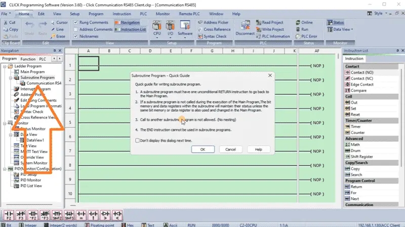
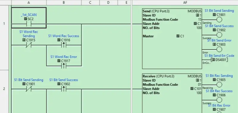
The first rung will have the first scan bit (SC2) used to trigger the first send communication instruction.
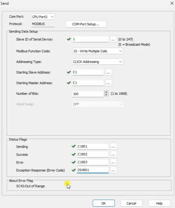
CPU Port 3 will be set for our Com Port for the send instruction. The protocol will be Modbus. We previously looked at the COM Port Setup, but if we do not know the parameters set, we can look at them again using this button. The Slave ID of the Serial Device will be set to one, and we will write multiple coils (Function Code 15). Click Addressing will be used for the addressing type. C1 will be the starting slave and starting master address. We will write 100 bits of information. Status flags play an essential role in this serial communication method.
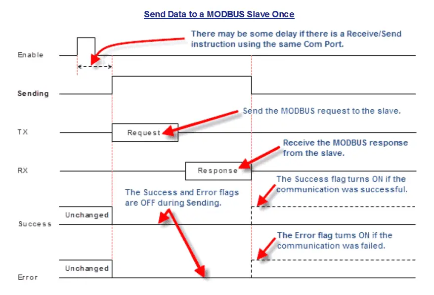
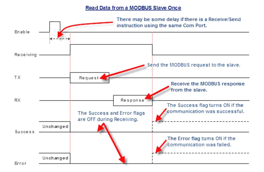
We will use these flags to trigger the next communication instruction. The following communication instruction flags will then trigger the next, etc. Here is the timing chart for the send command.
Assign a bit to each status flag and a register for the communication instruction’s status code. We will use the address picker to document these bits and words, which will help us as we continue to program.
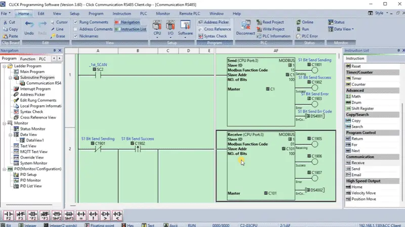
Rung 2 will now use the normally closed-sending flag with the leading edge of the send success or send error to trigger the receive instruction. We do not care if the send was successful; we want to keep the communication going.
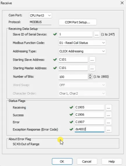
The Receive instruction will use CPU Port 3 with the Modbus protocol. With the slave ID 1, we will read the coil status using CLICK Addressing. The starting Slave address will be C101, and the starting Master address will also be C101. Just like the Send instruction, we will read 100 bits of information. Set and document the Status Flags so we can use them to trigger the next send word instruction.
Rung 3 will use the status flags from the Receive instruction to trigger the next Send instruction. The normally closed-sending flag with the leading edge of the send success or send error triggers the send instruction. Copying the previous send instruction, we will change the Modbus Function Code to Write Multiple Registers (16).
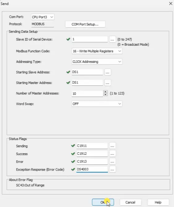
Ten master addresses starting at DS1 will be sent to the slave addresses starting at DS1. Status flags are set and documented for the next Receive instruction. The status flags from the previous communication send (write) register instruction will trigger the final Receive (read) register instruction.
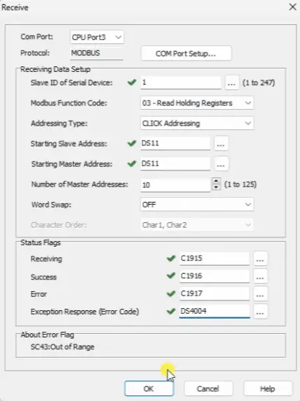
Copying the last Recieve bit instruction, we will change our Modbus Function Code to the Read Holding Register (03). The starting address for the master and slave will be DS11. We will read ten-word (register) addresses. Setting the status flags and document for this instruction will trigger the first Send instruction at rung 1.
Remember to save your program often as you program. This will ensure you do not lose any work if your computer crashes.
Place a Return instruction at rung 5 for our communication subroutine. You can see that we are just using the Modbus read and write commands in series. The status flags from one instruction trigger the next. The final instruction status flags trigger the first, and we start the communication again. This method of communication ensures the quickest system response.
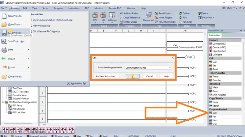
Returning to our Main Program under the navigation window, we can use the Call instruction to execute the communication subroutine every scan. Save and write the program into the Click PLC.
Click PLC PLUS Server (Slave) Modbus RTU Program
Call up the Click Programming Software. We will now create a program to control all the information on our RS485 Modbus RTU network.
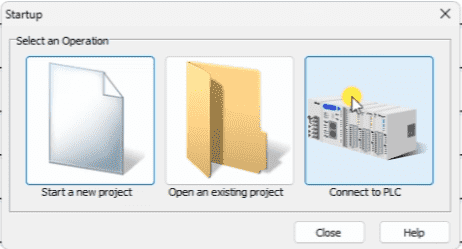
On the startup window, select “Connect to PLC”.
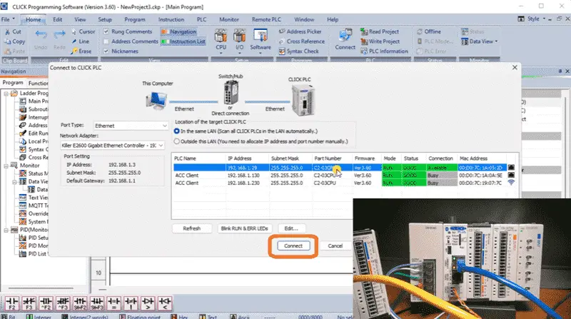
The “Connect to CLICK PLC” window will appear. The program will examine your network and report the available PLC connections. In our case, we can see two different PLCs. Our existing ACC Client can be seen for the WiFi and Ethernet connections. There is also another PLC with no name. Select this controller. If you are unsure of the correct connection, select “Blink RUN & ERR LEDs.” This will flash the lights so you can determine the PLC for the connection selected. Select Connect.
We will read the PLC program in the Click controller. The connection status will be displayed at the bottom of the software window. We can also highlight our logic by selecting the Status icon on the Home tab.
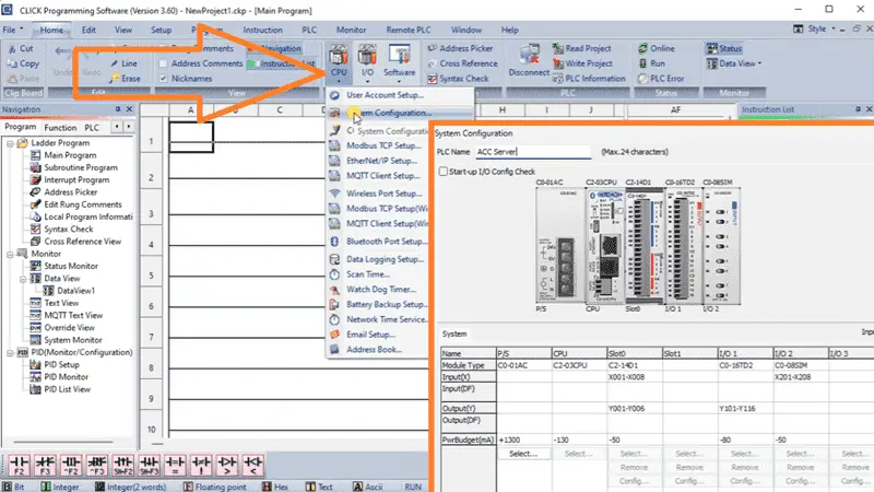
On the Home tab under CPU, select System Configuration… This will show you the physical PLC and the associated inputs and outputs we have connected. Give this PLC a name under the PLC Name. This will help us determine the PLC we will be communicating with in the future. We will name ours “ACC Server.” Select OK. Save the PLC program with a name we will remember in the future. Select save.
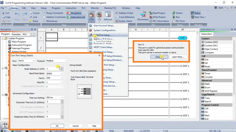
Select COM Port Setup… under the CPU icon on the Home tab. This will open the window displaying all available ports on the controller. Select Setup… for Port 3. This is the RS485 communication port. The port details will show you the setup for the physical communication. The protocol will be set for Modbus. We will leave the node address as the default one. The parameters will also be left as their default: 38400 baud, odd parity, one-stop bit, and 8-bit communication. We will also leave the advanced configuration for time-outs and response delays as their defaults. Select OK. Since we changed the configuration, we must write the project to our PLC controller.
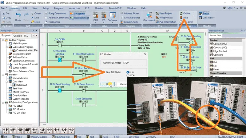
Returning to the Click Client (Master) program, we will stop and start the PLC. This will start our communications with the 1st scan flag. You will now see the LED lights blinking on the Click Server. Watch the video below to see how this is programmed and in operation.
Monitoring the Click Modbus RTU RS485 Network using Data View
Under the Monitor heading in the program tab, select Data View. This is in the Click Programming Software Navigation window. Right-clicking this data view window and selecting rename will allow us to rename it.
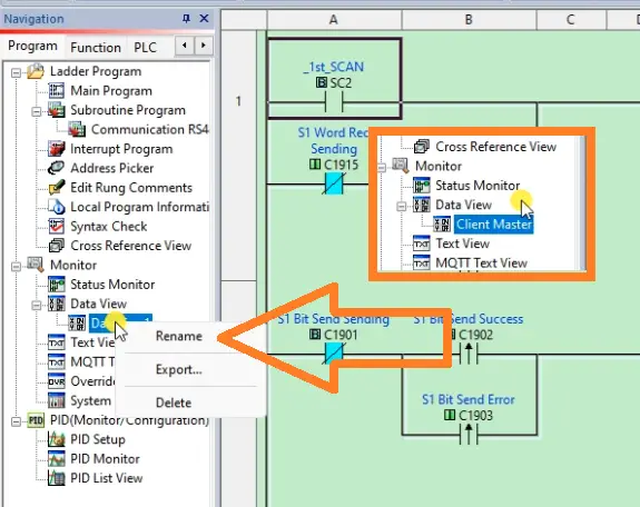
Double-clicking on the new title will display the data view window. The Data View window will display. We can now enter the bits and words we want to monitor for the RS485 Modbus network.
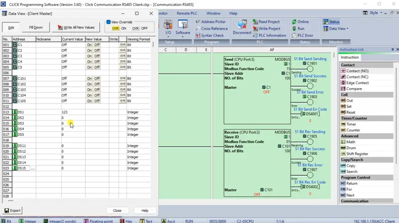
If we need consecutive addresses, we can quickly enter them by selecting the last address and pressing Ctrl + Enter. We will display ten bits and words. Finally, we should save the program so that our Data View information is saved.
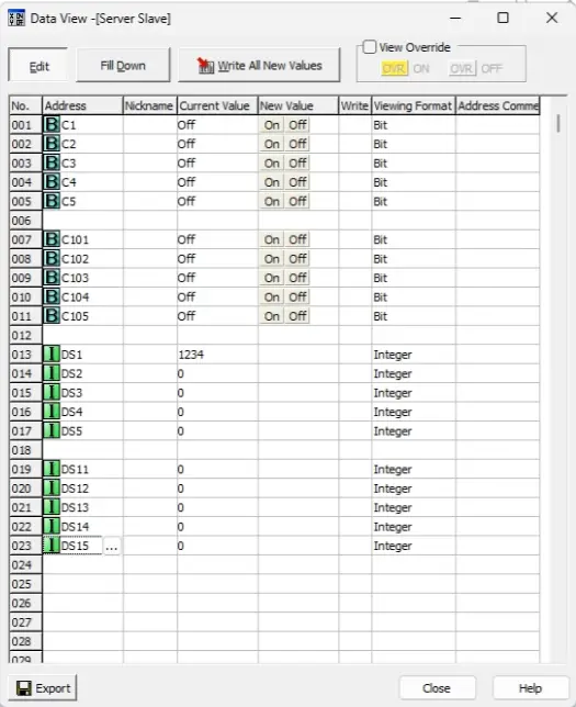
Call the Data View window for the Click Server on our Modbus network. Enter the same addresses as the Click Client, then save the program.
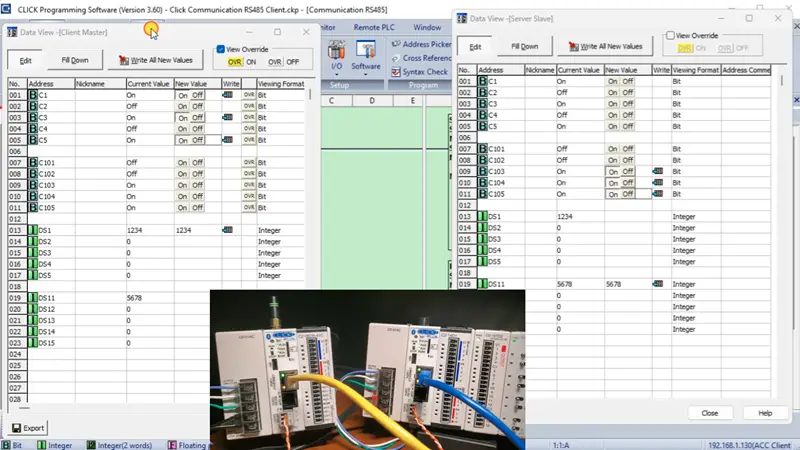
As we write the bits and words in the data view window for either the Client or Server, the corresponding bits and words will be changed in the other. Our communication is working; however, if communication is lost, the programs will no longer share information, and the controller will not know how to recover and continue communication. We will now examine how to correct and program this.
Creating a Heartbeat for Modbus RTU Serial Communications
A heartbeat bit will pulse on and off in the network for a timed duration. This can then be used to determine if communications are working or not. Our heartbeat bit will turn on for one complete send-and-receive instruction sequence and then turn off for another complete send-and-receive instruction sequence. We will add this heartbeat bit pulse at the end of the communication subroutine.
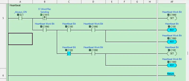
When the leading edge of our last communication instruction is triggered, this will set an internal bit (C1900) on. When this internal bit is on, and the heartbeat bit (C100) is on, C100 and C1900 are reset. When this internal bit is on and the heartbeat bit (C100) is off, set C100 and reset C1900. As you can see, the heartbeat bit will be triggered on/off with the leading edge of our last communication send flag. Using the address picker in the Click programming software, we can document the heartbeat and work bits for this circuit.
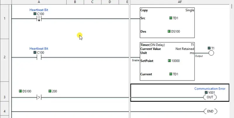
Returning to the Click Server Program, we can program the heartbeat bit logic. We will use a timer to determine the communications throughput on our Modbus RS485 network and whether communications are lost. The trailing edge of the heartbeat bit will copy the timer representing the communication throughput into a storage area. (DS100) The C100 heartbeat bit will then be used to determine the condition for timer 1, which will have a set point of 10000 milliseconds (10 seconds). The communication output error will be activated when the last communication timer is greater than 200 milliseconds. Remember to save and document as you program the controller. Our heartbeat circuit for the server now accounts for when the heartbeat bit is on.
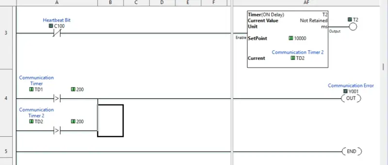
We must also create logic for when the bit is off. When the C100 heartbeat bit is off, it controls a second timer with the same preset as the first. If this timer exceeds 200 milliseconds, the output error bit will also turn on. Document, save, and transfer the Click Modbus RS485 server program to the controller.
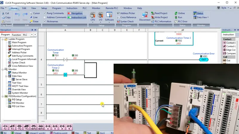
When testing the heartbeat circuit of the server PLC, we can disconnect the RS485 communication, and the output will turn on, indicating an error. Putting back the connection will restore the communication.
Monitoring and Resetting the Modbus Client Communication
Our current Click client program starts only on the first scan bit. We will modify it to detect a communication error and reset it using two timers.
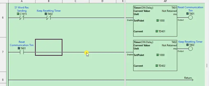
We will start the first timer using the not of the last sending bit flag instruction and the second timer. Each timer will have a preset value of 1000 milliseconds (1 second). The output of the first timer will start the second timer. We can document the timers using the “Address Picker” in the Click programming software.
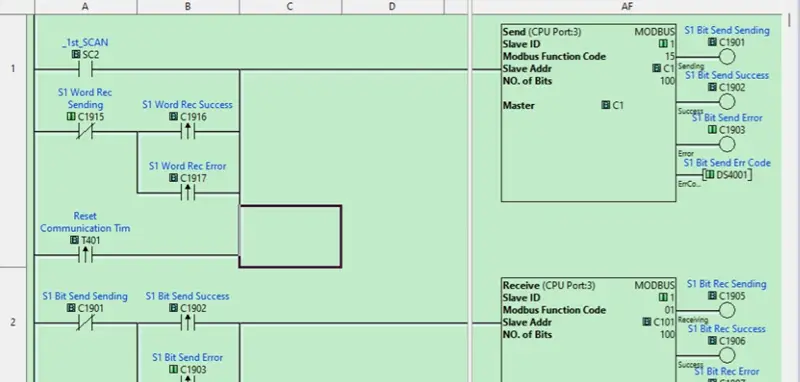
We can now add the leading edge contact of the first timer on the first rung. When the communication sequence does not execute in 1 second, this bit will trigger, starting communication again. The second timer is used continually every two seconds to trigger. One second is for the first timer, and then one second is for the second timer. We can save and transfer our program.
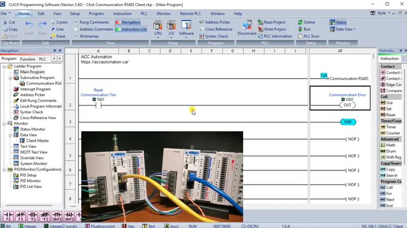
Then, moving back to the Main Program of the Client code, we can add our program to turn on an output when we detect a communication error. If the first timer expires, we will activate the first output. Document and transfer the program.
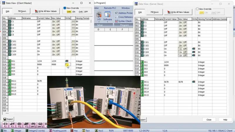
We can now call up the data view windows of both Click programs and test our communications.
Serial Modbus over RS-485 provides a versatile and robust solution for industrial communication. It facilitates interoperability between various devices and ensures reliable data transmission over long distances. We have learned the importance of Modbus RS485 in PLC communication and the steps to set it up effectively.
Our entire series on the Click PLC can be found here.
Click PLC Support Links
The Click PLC can be programmed using free Click programming software from Automation Direct.
Here is a link to the software. Version 3.60
The entire Click PLC series before the Click PLUS release can be found here.
All previous posts and information are still valid with the Click PLC line-up.
YouTube Click Playlist
YouTube Click PLUS Playlist
Click and Click PLUS PLC Overview
Click and Click PLUS PLC Videos from Automation Direct
Watch on YouTube: Master Click PLC Communication: Ignite your Modbus RS485 passion!If you have any questions or need further information, please contact me.
Thank you,
Garry
If you’re like most of my readers, you’re committed to learning about technology. The numbering systems used in PLCs are not difficult to learn and understand. We will walk through them, including Bits, Decimal, Hexadecimal, ASCII, and Floating Point.
To get this free article, subscribe to my free email newsletter.
Use the information to inform other people how numbering systems work.
Sign up now.

The ‘Robust Data Logging for Free’ eBook is also available as a free download. The link is included when you subscribe to ACC Automation.

