We will now look at the system hardware of the Omron CP1H controller. The Omron CP1 series of programmable logic controllers consists of three different units. CP1E is the cost-effective unit, CP1L is the high-performing controller that can come with embedded Ethernet and the Omron CP1H is the position control and comprehensive programmable logic controller.
We will be looking a the Omron CP1H for this series, but a majority of the information can be applied to the CP1E and the CP1L controllers as well.
Let’s start by looking at the Omron CP1H hardware.
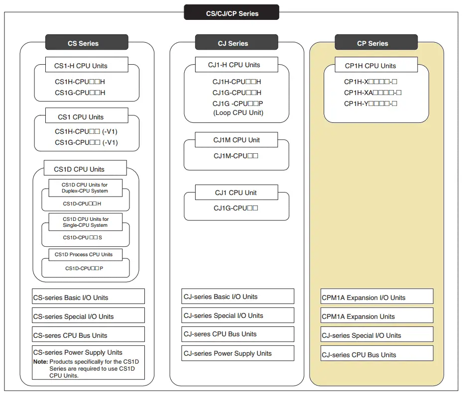
The CP1 series is designed with the same basic architecture as the CS and CJ Series. The special I/O units and CPU bus units of the CJ series can then be used. Always use CPM1A expansion units and CPM1A expansion I/O units when expanding the I/O capacity. The following diagram indicates the position of the unit with respect to the CJ and CS series hardware.

System Hardware – Video
CX-Programmer – Video
Establish Communication – Video
Setting, Forcing and Online Editing – Video
Numbering System and Addressing – Video
CP1H Timers – Video
Counters – Video
Data Movement – Video
Compare Instructions – Video
Data Shift Instructions
– Video Part 1
– Video Part 2
Math Instructions – Video
Data Conversion – Video
Program Control Instructions – Video
Table Data Instructions – Video
Data Control Instructions – Video
AdvancedHMI Communication – Video
Omron CP1H – System Hardware and Programming Manuals
The following is a list of manuals associated with the CP1H programmable logic controller.
W450 – SYSMAC CP Series CP1H CPU Unit Operation Manual – Provides an overview, mounting, I/O memory allocations, and troubleshooting
W451 – SYSMAC CP Series CP1H CPU Unit Programming Manual – Programming instructions, methods, and functions.
W342 – SYSMAC CS/CJseries Communications Commands Reference Manual – Describes commands addressed to CS and CJ series CPU units which include C-mode (Host Link)commands and FINS commands.
W446 – SYSMAC CX-Programmer Ver. 6.1 Operation Manual – Provides information on installing and operating a CX programmer for all functions except function blocks.
W447 – SYSMAC CX-Programmer Ver. 6.1 Operation Manual Function Blocks
W444 – CX-One FA Integrated Tool Package Setup Manual – Provides an overview of the CX-One FA Integrated Tool and installation procedures.
W445 – CX-Integrator Operation Manual – Describes CX-Integrator operating procedures and provides information on network configurations.
W344 – CX-Protocol Operation Manual – Provides information on procedures for creating protocol macros. (Communication Sequences)
Omron CP1H Hardware
All modes of the CP1H include the following hardware I/O features:
24 Inputs
– 8 Interrupt Inputs – Instructions are automatically executed when the input is activated. This will interrupt the current scan, execute the logic in the interrupt routine, and then return to the regular scan.
– 8 Quick Response Inputs – This is required when your signals into the controller are quicker than the scan of the PLC. These inputs can read signal inputs as quickly as 30 microseconds.
– 4 High-Speed Counter – 100 kHz single-phase inputs from encoders can be inputted directly to the CPU of the CP1H.
16 Outputs
– 2 pulse outputs can be set for 100 kHz
– 2 pulse outputs can be set for 30 kHz
– 2 PWM outputs can be set (Pulse Width Modulated)
The XA unit has 4 analog inputs and 2 analog outputs built into the base unit.
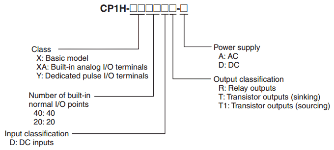
Here is a quick breakdown of the part number association of each of the units.

Since this hardware has been on the market for a few years you can purchase new and used systems on eBay, Amazon, or similar online sites.
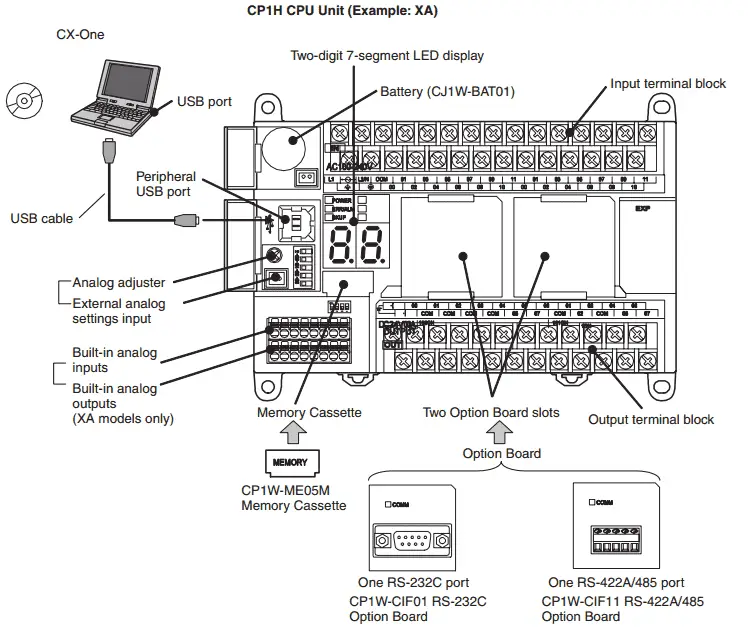
The following is a diagram of the basic configuration of our CP1H-XA unit.

Programming Port – The peripheral USB port is used with the CX-One (CX-Programmer) software to program the PLC. This is a dedicated port used only for this purpose.
Display – A two-digit 7 segment LED display is built into the base unit. This can be used in your program for anything you want. (Example – Error Messages, % display, etc.)
Battery – The CP1H CPU unit saves the backup data in the built-in flash memory (non-volatile memory) enables operation with not battery mounted. However, the memory that is memory retentive will rely on the battery to save its values. (HR, CNT, and DM Memory areas) The lithium battery is part number CJ1W-BAT01 and will save the information for a maximum of 5 years.
Analog adjustor – This is a pot located on the base unit and will provide an analog input to be used in your program. I have used this before to fine-tune parameters in the field. (Timers)
External Analog Setting Input – This is similar to the analog adjustor but you will provide an external potentiometer to the connector in order to adjust an analog input.
Memory Cassette – CP1W-ME05M – The device is not always necessary in every application. This memory cassette can be used to:
1 – Copy data to other CPU units to duplicate the device
2 – Back up data in case the CPU unit needs to be replaced due to a malfunction
3 – Writing and updating data when existing device versions are updated
Two Option Board Slots – These are used to attach additional communication units. These can be RS232C or RS422/485 option boards.
See this unit and other hardware features by watching the YouTube video below.
Next time we will look at CX-Programmer Software.
Watch on YouTube: Omron CP1H System Hardware
If you have any questions or need further information please contact me.
Thank you,
Garry
If you’re like most of my readers, you’re committed to learning about technology. Numbering systems used in PLC’s are not difficult to learn and understand. We will walk through the numbering systems used in PLCs. This includes Bits, Decimal, Hexadecimal, ASCII, and Floating Point.
To get this free article, subscribe to my free email newsletter.
Use the information to inform other people how numbering systems work. Sign up now.
The ‘Robust Data Logging for Free’ eBook is also available as a free download. The link is included when you subscribe to ACC Automation.


