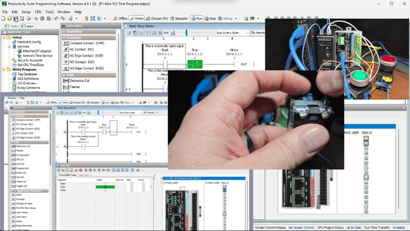
The Productivity Suite Software allows us to modify our existing program and execute the new code without stopping the PLC scan. This is referred to as online editing. We change the ladder logic code, and when we save it to the P1-M622-16DR PLC, the current PLC scan is held until the new code is written to the unit. It then releases the scan, and our new program begins executing. This happens in milliseconds, so our process can continue to operate.
In this post, we’re going to demonstrate something critically important: fail-safe wiring for stop circuits. We’ll show why our current wiring configuration is NOT fail-safe, rewire the stop button properly, and then use online editing to update our ladder logic to match—all without stopping the PLC.
This is a lesson that could save equipment, prevent injuries, or even save lives in a real industrial application.
Let’s get started.
Previously in this Productivity Mini PLC P1-M622-16DR series, we have discussed:
P1-M622-16DR Mini PLC System Hardware – Video
Installing the Software – Video
Establishing Communication – Video
First Program – Video
Monitoring and Testing the Program – Video
Wiring and Testing – Video
Online Editing and Fail-Safe Wiring – Video
Current Wiring Configuration Review
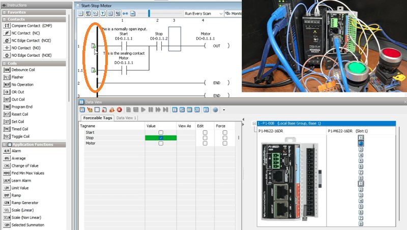
Let’s review our current wiring setup:
- Start Pushbutton – DI-0.1.1.1 – Wired Normally Open (NO)
- Stop Pushbutton – DI-0.1.1.2 – Wired Normally Open (NO)
- LED Light (Motor) – DO-0.1.1.1 – Represents the motor output
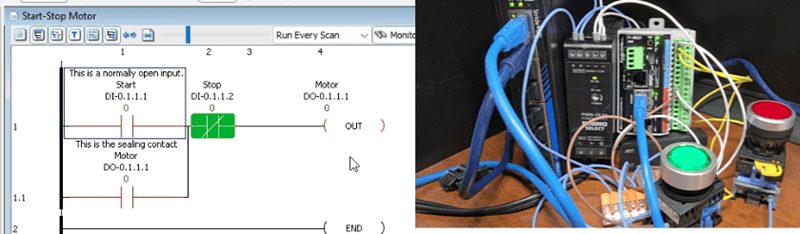
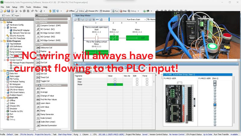
In our ladder logic, we’re using:
- A normally open (NO) contact for Start
- A normally closed (NC) contact for the stop
- An output coil for the Motor
The thinking behind this design was: “The physical stop button is normally open, so when pressed, it sends a signal to the PLC. We use an NC contact in the ladder so that when the input turns ON, the contact opens and breaks the circuit.”
This logic works perfectly… until something goes wrong.
Demonstrating the Problem – NOT Fail-Safe
Let’s test what happens when we simulate a wiring failure. This is the scenario every control engineer needs to understand.
Step 1: Start the Motor. With the PLC in Run mode, press the Start button. The motor output (LED) turns ON and seals in. Everything works as expected.
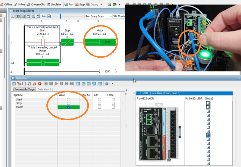
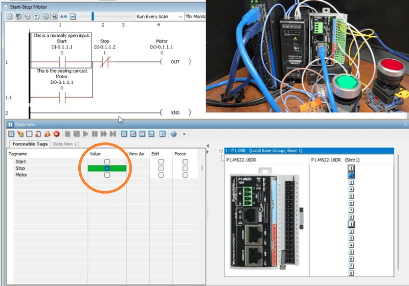
Step 2: Monitor the Circuit. Open the Data View panel (Ctrl + Shift + F3) so you can see the status of all our I/O points:
- DI-0.1.1.1 (Start) – OFF
- DI-0.1.1.2 (Stop) – OFF
- DO-0.1.1.1 (Motor) – ON
Also, enable monitoring in the ladder editor so you can see the logic flow.
Step 3: Simulate a Wire Failure Now, with the motor running, carefully remove one wire from the Stop pushbutton. This simulates what happens if:
- A wire breaks due to vibration
- A terminal connection comes loose
- A wire is accidentally cut
- Corrosion causes an open circuit
What Happens? NOTHING! The motor keeps running!
Look at the Data View—DI-0.1.1.2 (Stop) is still OFF. In the ladder logic, the NC contact for Stop remains TRUE (closed), allowing power to flow to the output.
The Critical Problem: If you try to press the Stop button now, nothing happens because the wire is disconnected. You cannot stop the motor using the Stop button. In a real industrial application, this could mean:
- An operator cannot stop a machine in an emergency
- Equipment damage continues unchecked
- Serious injury could occur
This is NOT a fail-safe design!
Understanding Fail-Safe Wiring
A fail-safe design means that when a failure occurs, the system defaults to the SAFE state. For stop circuits and emergency stops, the safe state is STOPPED.
The Rule: Stop buttons and Emergency Stop (E-Stop) buttons should ALWAYS be wired as normally closed (NC) contacts.
Here’s why this works:
Normally Closed Stop Button Wiring:
- Button NOT pressed: Contact is closed, current flows, input sees 24VDC (ON)
- Button pressed: Contact opens, current stops, input sees 0VDC (OFF)
- Wire breaks: Current stops, input sees 0VDC (OFF) – SAME AS PRESSING STOP!
With NC wiring, any failure in the stop circuit (broken wire, loose connection, failed switch) results in the same condition as pressing the stop button. The machine stops. This is a fail-safe.
Industry Standards: This isn’t just a good idea—it’s required by safety standards, including:
- NFPA 79 (Electrical Standard for Industrial Machinery)
- IEC 60204-1 (Safety of Machinery)
- OSHA regulations
Emergency stop circuits have additional requirements, including direct-acting contacts and self-monitoring, but the fundamental principle remains: NC wiring for stop functions.
Rewiring the Stop Button
Now, let’s make our wiring fail-safe.
Step 1: Power Down Safely. Before making any wiring changes, put the PLC in Stop mode or remove power. Never make wiring changes with the system energized.
Step 2: Replace or Rewire the Stop Button. Change the Stop pushbutton from a normally open (N O) contact to a normally closed (NC) contact:
Option A: Replace the button. If your stop button has N O contacts, replace it with one that has NC contacts (most industrial stop buttons are red and have NC contacts by default).
Option B: Use the NC contact. Many pushbuttons have both N O and NC contact blocks. Simply move your wires from the N O terminals to the NC terminals.
New Wiring:
- One side of the NC contact connects to 24VDC positive
- The other side of the NC contact connects to Input 2 (DI-0.1.1.2)
- Input common (C1) connects to 24VDC negative
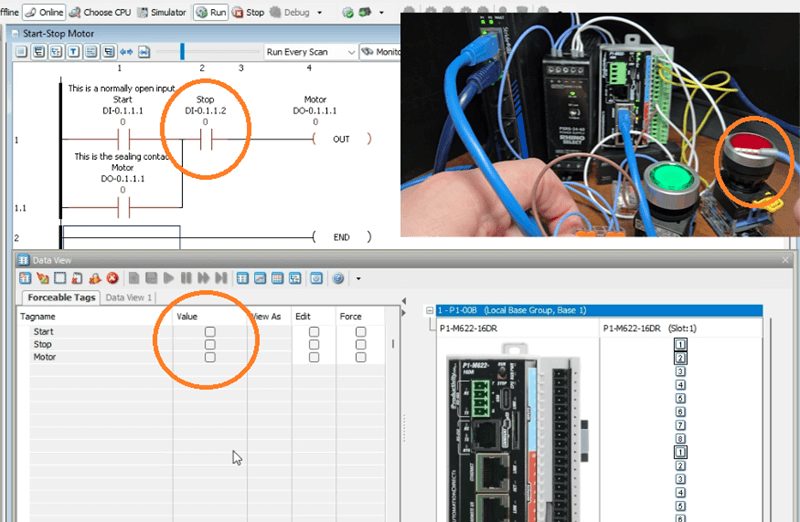
Step 3: Verify the New Wiring. Power up the PLC (keep it in Stop mode). Open Data View and observe:
- With the stop button NOT pressed, DI-0.1.1.2 should be ON (input sees 24VDC through the closed NC contact)
- Press the Stop button: DI-0.1.1.2 should turn OFF (NC contact opens)
This is the opposite behavior from before—and that’s exactly what we want!
The Ladder Logic Problem
Now we have a problem. Our ladder logic uses a normally closed (NC) contact for the Stop input. But with our new NC wiring:
- Stop NOT pressed: Input is ON, NC ladder contact is FALSE (open) – Motor can’t run!
- Stop pressed: Input is OFF, NC ladder contact is TRUE (closed) – This is backwards!
We need to change the ladder logic to use a normally open (NO) contact for the Stop input. This way:
- Stop NOT pressed: Input is ON, NO ladder contact is TRUE (closed) – Motor can run
- Stop pressed: Input is OFF, NO ladder contact is FALSE (open) – Motor stops
Online Editing – Making the Change
Here’s where online editing becomes valuable. We can make this change while the PLC is running, minimizing downtime.
Step 1: Connect and Go Online. Make sure you’re connected to the P1-M622-16DR via USB-C or Ethernet. The PLC should be in Run mode with the CPU selector switch set to RUN.
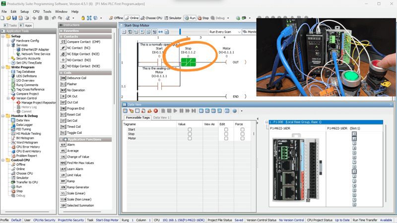
Step 2: Locate the Stop Contact. In the ladder editor, find the NC contact for DI-0.1.1.2 (Stop) in your start-stop motor rung. This will now be highlighted.
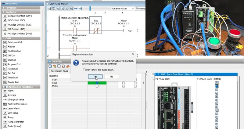
Step 3: Change the Contact Type. Locate the N O Contact under the Contacts instructions. Double-click on the N O contact. The Replace Instruction window will now be shown. Select Yes to replace the Normally Closed (NC) with the Normally Open (N O).
Step 4: Notice the Unsaved Indicators. You’ll see symbols appear on the left side of the modified rung, indicating that the program has been changed but not saved or transferred to the CPU.
Step 5: Save the Project. Select File | Save Project or click the Save icon. The symbols will change to indicate the project is saved but not yet transferred.
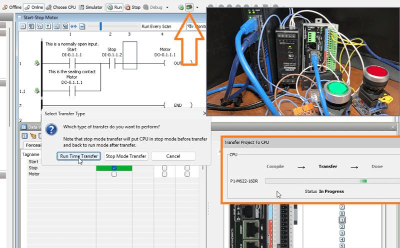
Step 6: Transfer Using Run Time Transfer. Select File | Transfer Project | To CPU, or click the Transfer icon, or press Shift + F9.
The Select Transfer Type window appears. Select Run Time Transfer. This option transfers the new program while the PLC continues to run.
Click OK to begin the transfer.
Step 7: Verify the Transfer. The Transfer Project to CPU window shows the transfer progress. When complete, the ladder logic will resume monitoring with the new code in effect.
The entire transfer happens in milliseconds—the PLC scan is briefly held while the new code is written, then execution continues with the updated program.
Testing the Fail-Safe Circuit
Now let’s verify our fail-safe design works correctly.
Watch the video below to see this in operation.
Test 1: Normal Operation
- Press Start – Motor turns ON
- Release Start – Motor stays ON (sealed)
- Press Stop – Motor turns OFF
- Release Stop – Motor stays OFF
Test 2: Fail-Safe Test
- Press Start – Motor turns ON
- With the motor running, remove a wire from the Stop button
- The motor should immediately turn OFF!
Why This Works: When you remove the wire, the input loses its 24VDC signal and turns OFF. In the ladder logic, the NO contact for Stop opens (becomes FALSE), breaking the circuit. The motor stops.
This is a fail-safe operation! Any failure in the stop circuit—broken wire, loose terminal, or failed switch—automatically stops the motor.
Test 3: Compare to Before. Remember what happened with the old normally open wiring? The motor kept running when we removed a wire. Now it stops. That’s the difference between a dangerous circuit and a safe one.
Summary: The Complete Picture
Let’s summarize what we’ve learned:
| Configuration | Physical Button | Ladder Contact | Fail-Safe? |
|---|---|---|---|
| Original | NO | NC | NO – Wire break = motor keeps running |
| Corrected | NC | NO | YES – Wire break = motor stops |
The Rules to Remember:
- Stop buttons and E-Stops should ALWAYS be wired with NC contacts
- When using NC wired buttons, use NO contacts in the ladder logic
- The combination of NC wiring + NO ladder contact creates a fail-safe operation
- Test your fail-safe circuits by simulating wire failures
Online Editing Benefits:
- Make changes without stopping production
- Test modifications in real-time
- Minimize downtime during troubleshooting
- Quickly respond to safety concerns
Productivity Mini PLC P1-M622-16DR from AutomationDirect
Overview Link (Additional Information on the Unit) Configuration (Configure and purchase a system – BOM) User Manual and Inserts (Installation and Setup Guides) Productivity Suite Programming Software (Free Download Link)
This software contains all of the instruction sets and help files for the Productivity Series.
Next time, we will look at using the PLC Simulator on the Productivity Suite Software.
Watch on YouTube: P1-M622-16DR PLC – Learn Now Online Editing and Fail-Safe Wiring!
If you have any questions or need further information, please contact me.
Thank you,
Garry
Related Posts:
- Productivity 1000 Series PLC Live Modification & Run Mode!
- How to Make a Start-Stop Jog Circuit in a PLC
- P1-M622-16DR Mini PLC Wiring and Testing
There are many PLC manufacturers offering various hardware and software. All programmable logic controllers share similar basic features. Here is how I would approach learning about basic PLCs.
Once you are familiar with the basics of the PLC, you will learn the specifics of the controller you will be programming.
This is the easiest way to learn about PLC programming.
Here are the controllers that we have covered or are covering at ACC Automation:
LS Electric XGB PLC Series
BRX Do-More Series (Do-More Designer Software + Simulator)
Productivity Series P1000 / P2000
Click PLC Series
Omron CP1H Series
Horner XL4 PLC Series
Arduino Opta PLC
The EasyPLC Software Suite is a comprehensive package that includes PLC, HMI, and machine simulator software. This allows you to make a digital twin. See below to receive 10% off this software. This PLC learning package contains the following:
Easy PLC – PLC Simulation will allow programming in Ladder, Grafcet, Logic Blocks, or Script.
HMI System – Easily create a visual human-machine interface (HMI)
Machine Simulator – A virtual 3D world with real-time graphics and physical properties. PLC programs can be tested using the EasyPLC or through other interfaces. (Modbus RTU, TCP, etc.)
Machine Simulator Lite – Designed to run on Android Devices.
Machine Simulator VR – Virtual Reality comes to life so you can test, train, or practice your PLC programming.
Purchase your copy of this learning digital twin package for less than $95 USD for a single computer installation or less than $110 USD to allow access on multiple computers.
Receive 10% off the investment by typing in ACC in the comment section when you order.
Learn PLC programming the easy way. Invest in yourself today.
Examples of PLC program development using the five steps.
Click PLC – Easy Transfer Line Programming – Video
Productivity PLC Simulator – Chain Conveyor MS – Video
Five Steps to PLC Program Development – Die Stamping
PLC Programming Example – Process Mixer
PLC Programming Example – Shift Register (Conveyor Reject)
PLC Programming Example – Paint Spraying
PLC Programming Example – Delay Starting of 7 Motors
PLC Programming Example – Pick and Place
PLC Programming Example – Sorting Station (Shift Register)
PLC Programming Example – Palletizer
If you’re like most of my readers, you’re committed to learning about technology. The numbering systems used in PLCs are not difficult to understand. We will walk through the numbering systems used in PLCs. This includes Bits, Decimals, Hexadecimal, ASCII, and Floating Points.
To get this free article, subscribe to my free email newsletter.
Use the information to educate others on how numbering systems work. Sign up now.

The ‘Robust Data Logging for Free’ eBook is also available as a free download. The link is included when you subscribe to ACC Automation.