All programmable logic controllers (PLC) have the same numbering system at their core. This is the same with all computers as well. The status of any memory location can be either on or off. A one (1) will represent an on or “True” status and zero (0) will represent an off or “False” status. This is called binary.
Understanding PLC Numbering Systems
We will be looking at how numbering systems work and some of the common systems that programmable logic controllers use. Let’s get started.
Previously in this PLC Learning Series:
PLC Training Series – Tutorial for Everyone – Video
What are PLC Inputs? – Video
What are PLC Outputs? – Video|
Memory Backup – Video
How Numbering Systems Work
Number systems use different number bases. A number base indicates how many different digits are available when using a particular numbering system. For example, decimal is number base 10, which means it uses ten digits: 0, 1, 2, 3, 4, 5, 6, 7, 8, and 9. … We use the number to base 10 whereas PLCs (computers) use binary.
Let’s look at an example of our decimal numbering system. This will help us to understand how we can determine other numbering systems.
The number 3527 is comprised of 4 digits.
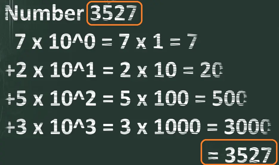 In calculating the value of the number we looked at each digit and multiplied it by the maximum value it could be based on its position within the number. This is called positional notation.
Example: 5 x 10^2 is the value 5 multiplied by the number of symbols that are available. (10) The exponent represents the place value 2. This means that it is the third location from the right.
So we just proved that 3527 is equal to 3527.
Our decimal numbering system is Base-10. This is formally written with a 10 written to the right lower hand corner of the value. Since base-10 is automatically assumed, we usually do not include this when writing the number.
Applying the same principles to a binary number will show you the value of the combined binary number.
PLC Binary to Represent Numbers
A single binary number is either 1 or 0. Combining these binary numbers together can form a value. Using the positional notation system, we can determine this value of the combined binary number.
1111 in binary is equivalent to:
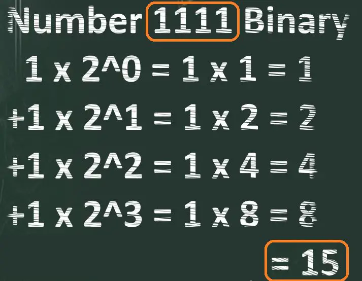 This means that we can combine four binary wires, switches, etc. together and have a maximum value of 15. If we include all of the inputs off (0000) we would have 16 possible combinations.
PLC Binary to Hexadecimal
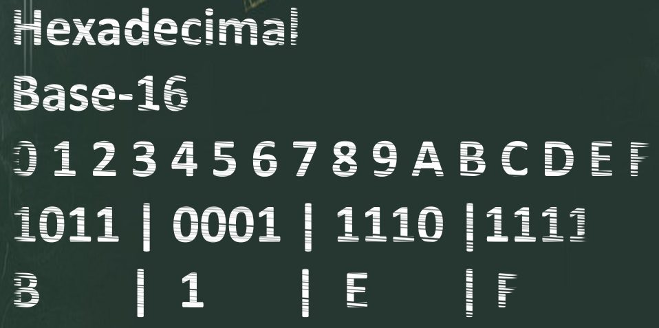
Having a number like 1011000111101111 binary is very difficult to read and quickly determine the value. Hexadecimal is used to represent a binary value. The base number of 16 is used in hexadecimal because this is the maximum combination of numbers that can be represented with four digits of binary.
Hexadecimal is a Base-16 system. This means that it has 16 symbols to represent each placeholder in the hexadecimal number. The values 0 to 9 would be the same symbols as the Base-10 decimal system. Values 10 to 15 would be represented by A to F.
Let’s take a look at the binary number 1011000111101111. We can break down this number by separating every 4 binary digits into a hexadecimal equivalent.
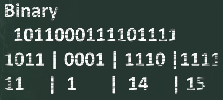
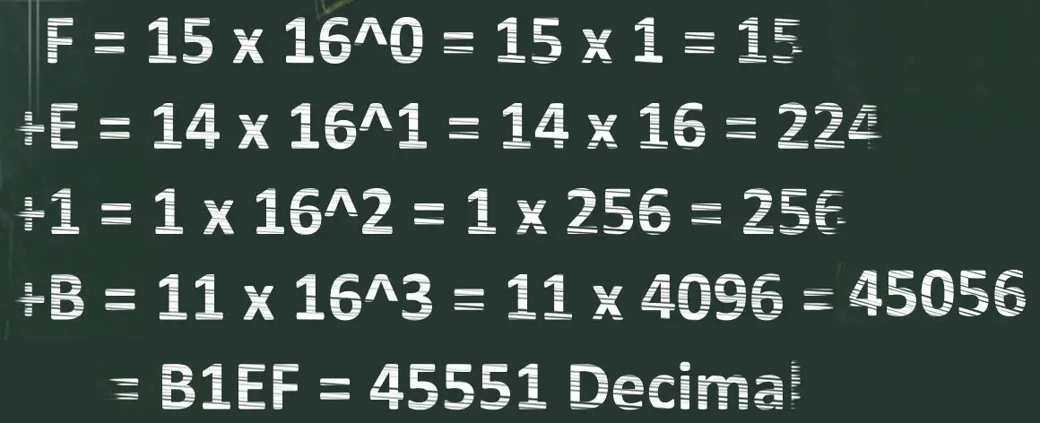 So we can see that the 1011000111101111 binary is equal to the B1EF hexadecimal. B1EF hexadecimal is equal to 45551 decimal.
PLC Binary Coded Decimal (BCD)
You must be now thinking that this is becoming very complicated math, just to find value. The values in the PLC are usually not this complicated. Hexadecimal is just used to represent a binary value. Instructions used in the PLC program will determine the numbering system to be displayed. The important thing to remember is the PLC will only understand a 1 or 0. Since we are very accustomed to the Base-10 or decimal system, the PLC will sometimes use Binary Coded Decimal or BCD values. Just as this name applies, the maximum value represented by the four bits will be 9. You must review your specific controller to determine how and which numbering systems are used.
PLC Binary to Hexadecimal using Windows Calculator
Windows has a good program for programmers. It is the windows calculator and is installed and available on all windows operating systems.
Call up the calculator by the search for it in the search box.
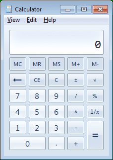 The standard windows calculator will be displayed.
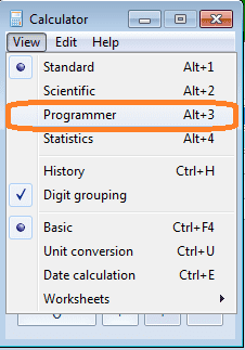 Select from the main menu | View | Programmer. You can also use the key combination of Alt + 3 to call up the programmer calculator.
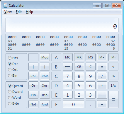 The default numbering system is Dec (decimal).
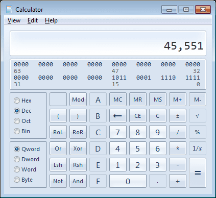 Enter the decimal value of 45551. Select the Hex (Hexadecimal) radio button.
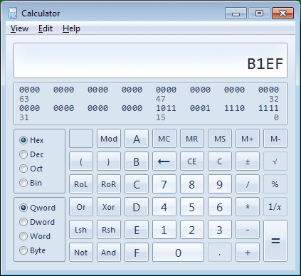 You will now see the same value that we have calculated above. If you look under the number you will see the binary bit locations 0 to 15 representing the binary value. This can also be displayed on the result window by select the Bin (binary) radio key.
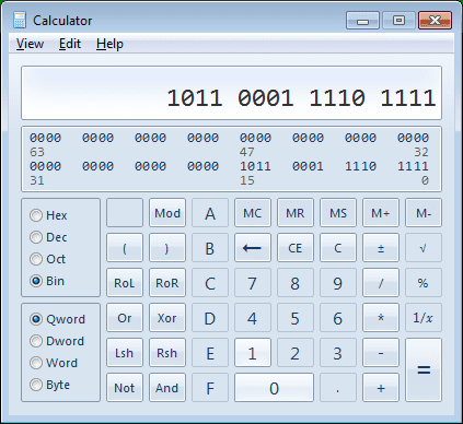 We now see the original binary 16-bit value. This program is great to quickly check or convert from different numbering systems.
Watch the video below to see the windows calculator in action.
PLC Beginner’s Guide to PLC Programming
There are many different PLC manufacturers with different hardware and software. All of the programmable logic controllers have similar basic features. Here is how I would approach learning about basic PLCs.
Once you are familiar with the basics of the PLC, you will then learn specifics for the controller you will be programming.
This is the easiest way to learn about PLC programming.
Watch on YouTube: PLC Learning Series – Understanding Number Values
If you have any questions or need further information, please contact me.
Thank you,
Garry
If you’re like most of my readers, you’re committed to learning about technology. Numbering systems used in PLCs are not difficult to learn and understand. We will walk through the numbering systems used in PLCs. This includes Bits, Decimals, Hexadecimal, ASCII, and Floating Points.
To get this free article, subscribe to my free email newsletter.
Use the information to inform other people how numbering systems work. Sign up now.
The ‘Robust Data Logging for Free’ eBook is also available as a free download. The link is included when you subscribe to ACC Automation.

