We will use the PLC to sort items on a conveyor operating shift register instructions. We will apply the five steps to a PLC example program development of a sorting station. The program will use shift registers to track colored parts down a conveyor and sort, depending on color, into one of three locations.
Developing the PLC program example is a process that can be clearly defined. We have done some similar practical examples in our series on the five steps to PLC program development.
Five Steps to PLC Program Development
– Press
– Process Mixer
– Shift Register (Conveyor Reject)
– Paint Spraying
– Delay Starting of 7 Motors
– Pick and Place
Define the task: (Step 1 – Sorting Station Shift Register)
Watch the sequence of operation video below.
Watch on YouTube: PLC Programming Example – Sorting Station Testing
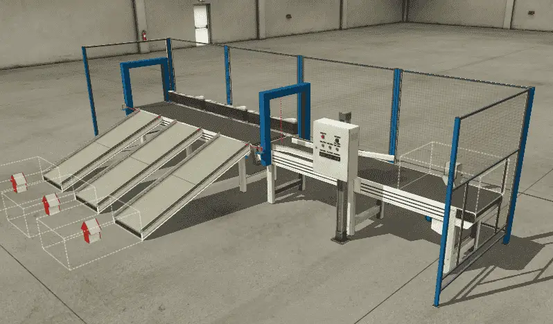
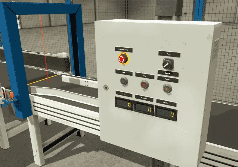 A normally open start and normally closed stop pushbuttons are used to start and stop the process in automatic mode. Upon beginning the entry, exit, and sorting station, belt conveyors will turn on. This will bring parts to the vision sensor.
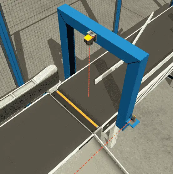 Each part will be tracked down the conveyor belt until it is in front of the appropriate exit ramp. (Three Ramps)
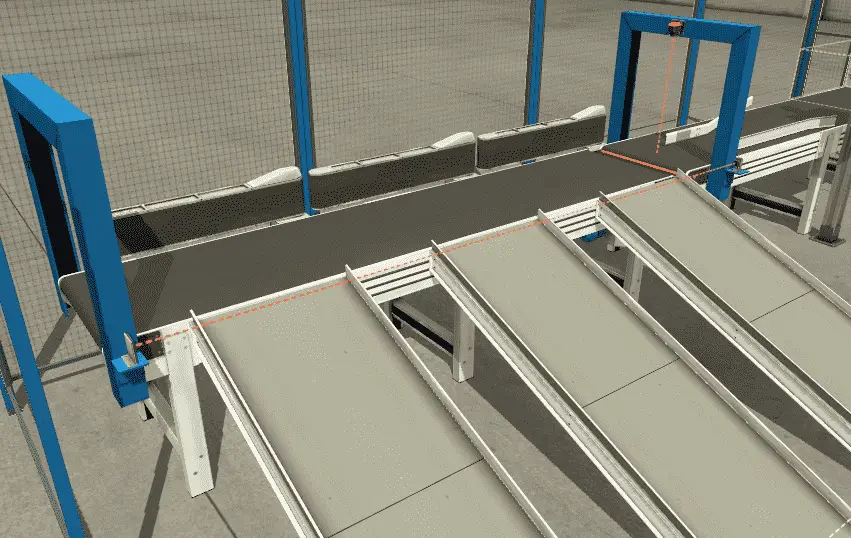 The sorting station diverter for the exit ramp will turn on, allowing the part to slide down the exit ramp.
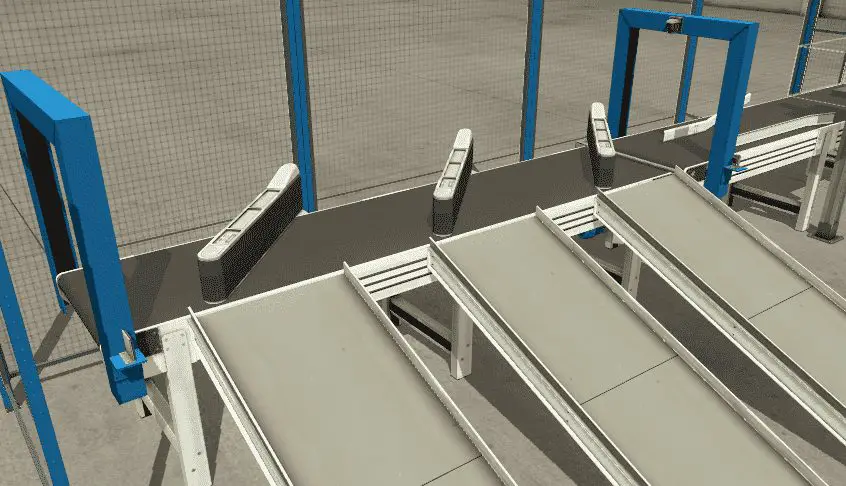 The number of sorted parts is tracked by a counter that will display the number of features sorted for the exit ramp. Hitting the reset when the panel is in manual mode will allow the counters to reset to zero. (0)
To reset the tracking of the parts and clear the conveyors, hit the reset button when the machine is stopped.
If a part is stuck on the exit sensor to the ramp, this will block the sensor. A delay of 5 seconds takes place, and then the machine will stop. The flashing reset button indicates a jam has occurred at the exit.
Define the Inputs and Outputs: (Step 2 – Sorting Station Shift Register)
Inputs:
Item at Exit – Sensor – On/Off – Normally Closed
Start Pushbutton – Normally Open – On/Off
Reset Pushbutton – Normally Open – On/Off
Stop Pushbutton – Normally Closed – On/Off
Emergency Stop – Normally Closed – On/Off
Auto / Manual – Switch – On/Off
Outputs:
Entry Conveyor – Contactor – On/Off
Stop Blade – (Not used)
Exit Conveyor – Contactor – On/Off
Sorter 1 Turn – On/Off
Sorter 1 Belt – Contactor – On/Off
Sorter 2 Turn – On/Off
Sorter 2 Belt – Contactor – On/Off
Sorter 3 Turn – On/Off
Sorter 3 Belt – Contactor – On/Off
Start Light – On/Off
Reset Light – On/Off
Stop Light – On/Off
Vision Sensor (Colour Sensor) – Register – 16 bits
Counter 1 exit ramp – Register – 16 bits
Counter 2 exit ramp – Register – 16 bits
Counter 3 exit ramp – Register – 16 bits
Develop a logical sequence of operation: (Step 3 – Sorting Station Shift Register)
A flow chart or sequence table is used to understand the process that needs to be controlled thoroughly. It must also answer questions like the following:
What happens when electrical power and/or pneumatic air is lost? What happens when the input / output devices fail? Do we need redundancy?
Knowing all of these answers upfront is vital in developing the PLC program. This step is where you can save yourself a lot of work by understanding everything about the operation. It will help prevent you from continuously re-writing the PLC program logic.
The main part of the program will be to track the pieces down the conveyor belt. Using a shift register on each exit ramp is an excellent way to do this logic.
Here is a review of how shift registers work:
https://accautomation.ca/plc-programming-example-shift-register-conveyor-reject/
In our example, we do not have an input representing movement on the conveyor belt. This would be like a proximity sensor on a sprocket or an encoder on the conveyor shaft. We will accomplish this by using a system timed bit. (100ms interval) When the conveyor belt runs, we will trigger our shift register every 100ms. This will act as the clock input to our instruction. Each 100ms pulse of the bit will indicate a movement of the conveyor belt.
Develop the PLC program: (Step 4 – Sorting Station Shift Register)
Writing the code for the PLC example will be the next step in our program development. A quick review can be seen on our post: Buiding A PLC Program That You Can Be Proud Of
(This series takes you through using discrete inputs and outputs to control traffic lights and cylinders. As we progress, we introduce additional methods to solve logic. We look at sequencers in a new way and learn how to write programs to allow users to teach the new sequence.)
The first thing in our program is to control the start and stop functions. This is done through a latching circuit.
Start / Stop Control Circuit
 Start the conveyors in the system. This is done with the start light bit.
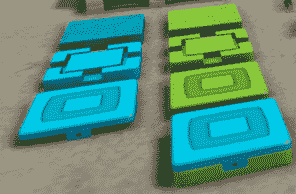
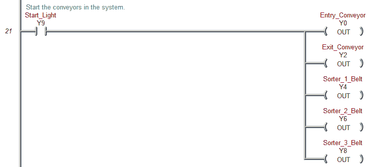 The color sensor on the input (MHR1) will determine the product’s color. The product will be sorted into one of three ramps based on color. The three sorting station ramps are tracked by their shift register.
The clock input to all three shift registers will be the start bit and a 0.10-second system clock bit (100 msec). Usually, this would be off of a conveyor pulse bit representing the distance traveled by the conveyor. Example: Gear turning triggers a proximity sensor.
Reset on the part tracking (shift registers) is done with the reset button when the system has stopped.
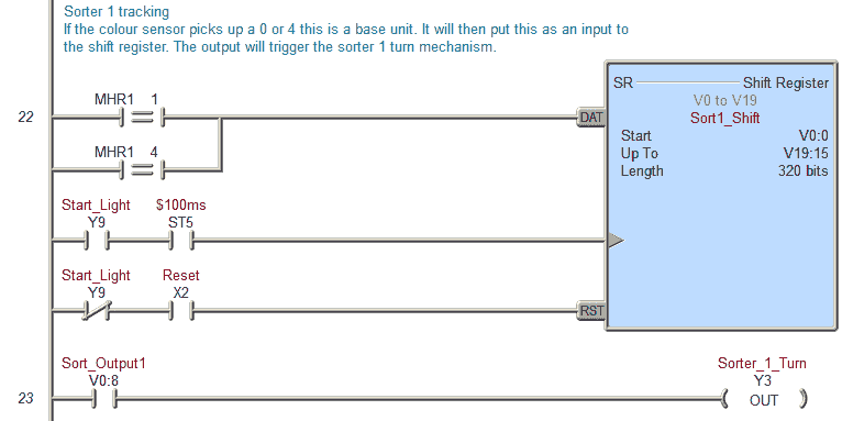
Sorter 1 tracking
This is a base unit if the color sensor picks up a 0 or 4. It will then put this as input to the shift register. The output will trigger the sorter one-turn mechanism.
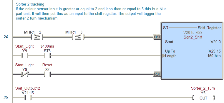
Sorter 2 tracking
If the color sensor input is greater or equal to 2 and less than or equal to 3, this is a blue part unit. It will then put this as input to the shift register. The output will trigger the sorter’s two-turn mechanism.
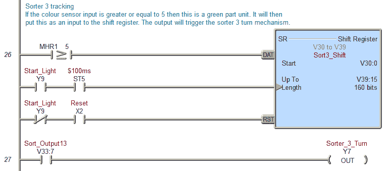
Sorter 3 tracking
If the color sensor input is greater or equal to 5, this is a green part unit. It will then put this as input to the shift register. The output will trigger the sorter three-turn mechanism.
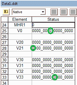
The actual output from each shift register will have to be experimented with during the testing of the program. In our case, Sort1 bit V0:8, Sort2 bit V21:15, and Sort3 bit V33:7 was used.
Counters
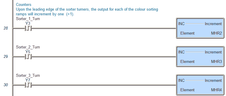 Upon the leading edge of the sorter turners, the output for each color sorting ramp will increment by one (+1).
Reset Light
 Will flash at 1-second intervals if the product is jammed on the output conveyor
The light will be on when reset is pressed.
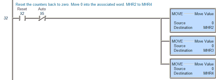 Reset the counters back to zero. Move 0 into the associated word. MHR2 to MHR4
Product Jam

Product Jam at exit Timer. If the sensor is off for more than 5 seconds, this will allow the timer to finish and produce an error.
This is the end of our program.
Test the program: (Step 5 – Sorting Station Shift Register)
We will be using Factory IO to test the program. This communicates Modbus TCP Client (Master) to our BRX Series PLC (Modbus TCP Server (Slave)).
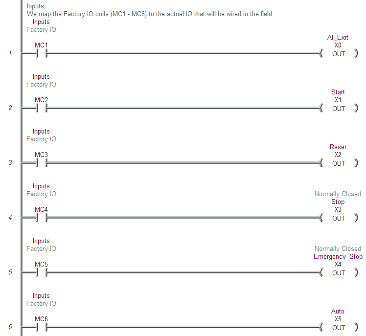
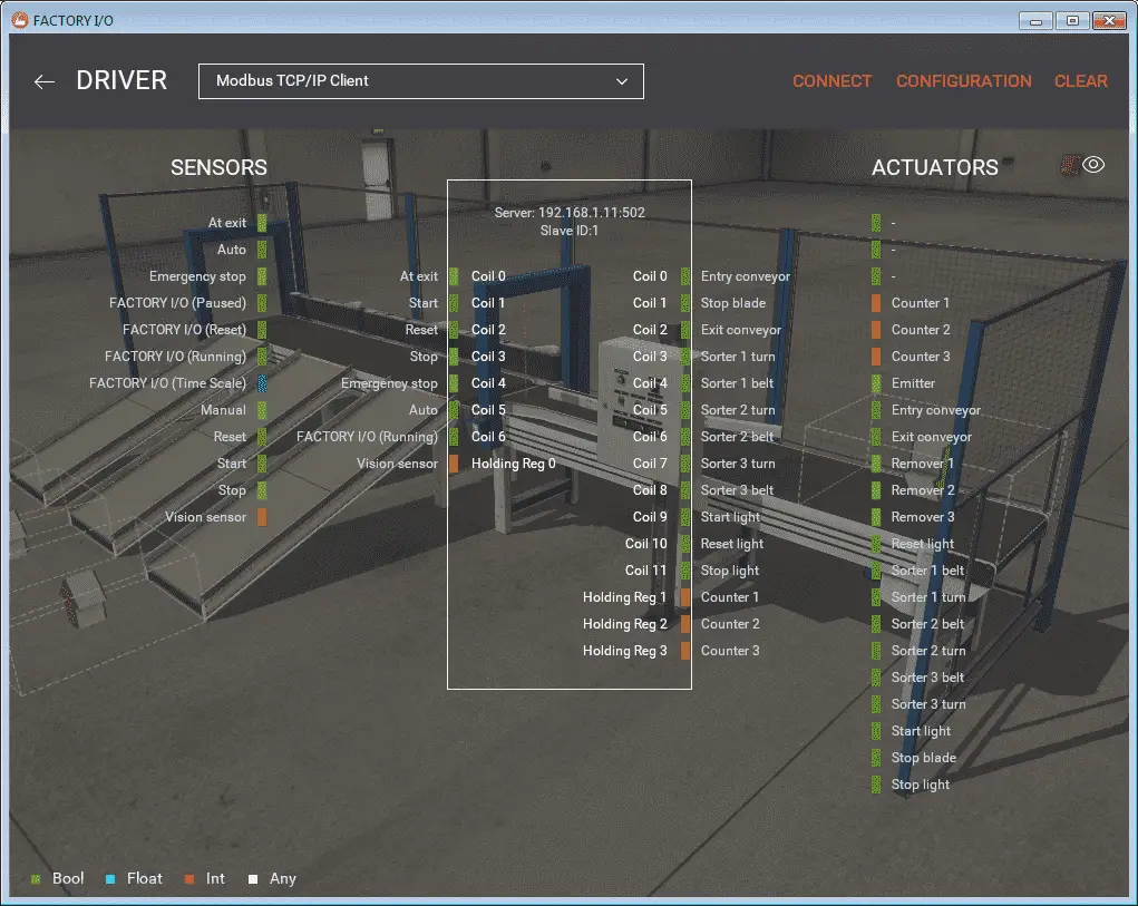 We will now add the inputs and outputs to our program for communication to our scene in Factory IO. The output coils from Factory IO will set the actual input addresses in our PLC example program. This will demonstrate how we can set the actual PLC inputs. See the following post on Understanding the PLC Program Scan.
The actual outputs will set the inputs from Factory IO from our PLC example program.
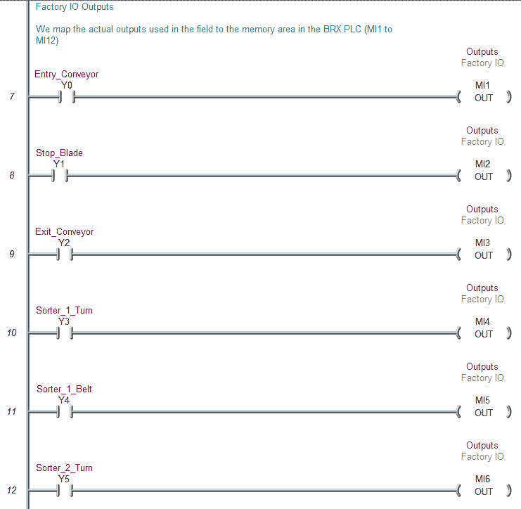
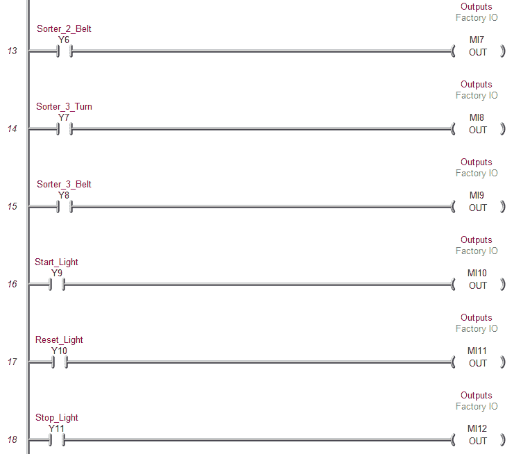
The first step in testing the program is ensuring that the PLC’s inputs and outputs are wired correctly. We would usually turn each input on manually and see the corresponding input of the PLC turn-on. The same applies to the output devices. We will turn on each of the outputs to determine if they have been wired correctly.
If everything is working, we will start running our program automatically.
Fine adjustments may be required for the output bits of the sequencers. In our example, we use the following bits within each sequencer instruction. (Shift Registers)
Test the program for things that can go wrong. Unplug a sensor or remove a box after the sensor has seen it. The PLC example program should be able to react.
Watch the video below to see an explanation and test of the program using Factory IO.
You can download the program and Factory IO scene here.
Watch on YouTube: PLC Programming Example – Sorting Station
If you have any questions or need further information, please get in touch with me.
Thank you,
Garry
If you’re like most of my readers, you’re committed to learning about technology. Numbering systems used in PLCs are not challenging to learn and understand. We will walk through the numbering systems used in PLCs. This includes Bits, Decimals, Hexadecimal, ASCII, and Floating Points.
To get this free article, subscribe to my free email newsletter.
Use the information to inform other people how numbering systems work. Sign up now.
The ‘Robust Data Logging for Free’ eBook is also available as a free download. The link is included when you subscribe to ACC Automation.

