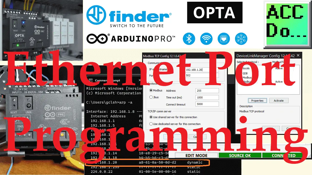
The Arduino Opta IoT PLC offers a hassle-free programming experience through its integrated Ethernet feature and efficient Arduino PLC IDE software.
First, we’ll connect the Ethernet cable to the OPTA IoT PLC and find its IP and MAC address. After that, we’ll configure the default programming port to Modbus TCP (Ethernet) via the Arduino PLC IDE. Finally, we’ll compile and transfer our PLC code to the OPTA. Let’s begin.
The entire Arduino Opta IoT PLC Series is located here.
Previously in this series, we have discussed the following:
Opta Introduction Video
Arduino Opta IoT PLC Cutting Edge Hardware – Video
Arduino Opta Software Installation – Video
Arduino Opta IoT PLC Quick Start Ladder Logic – Video
Easy Steps to Establish Communication between Arduino Opta IoT PLC – Video
Arduino PLC IDE Workspace: Unleash the Power! – Video
Note: A post is usually associated with each video. This will provide additional details and links discussed.
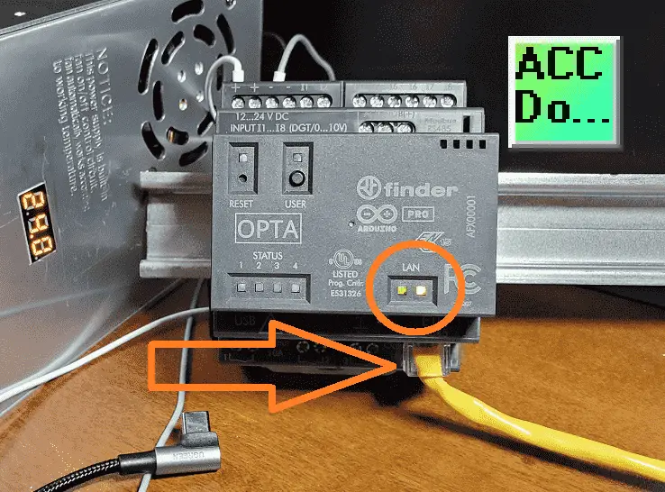
Finding Opta PLC Ethernet Port IP address
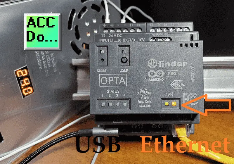
Plug the Ethernet cable into the Opta PLC.
This should automatically assign an IP address to the OPTA on your network using DHCP. DHCP (Dynamic Host Configuration Protocol), assigns IP dynamic addresses to hosts as soon as they enter the network. In a home or small network, the DHCP server is usually a part of the router. When you come into the network, the router will look for an available IP address in its pool and assign it to you, so that your device can communicate with others without any conflict. We will now need to find out this IP address.
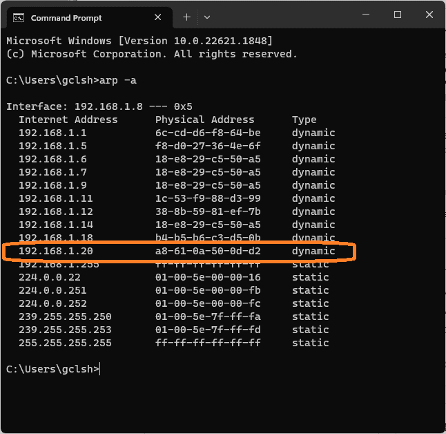
Call up a command prompt window. Enter the command “arp -a” to get a list of all other IP addresses active on your network. This will show you the IP or internet address and the controller’s physical (MAC) address. A MAC (Media Access Control) address is the hardware or physical address. It is a unique, 12-character hexadecimal number that is used to identify individual devices on your network.
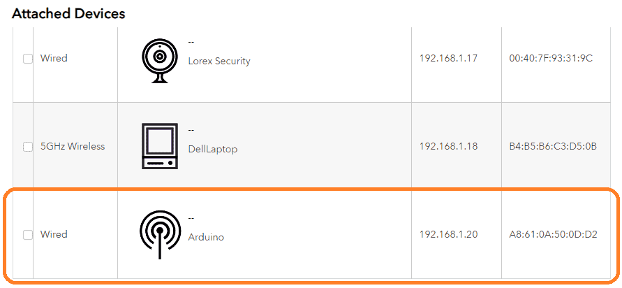
This IP and MAC address for the connected OPTA PLC can also be found using your router. Once you are logged into your router, look at the connected devices. The Arduino controller connected will be displayed. Each router method differs, so refer to your router’s manual to see connected devices.
Dynamic VS Static IP Address
As mentioned above, when connecting a device to your network, the DHCP will automatically assign a dynamic IP address to the device. However, the IP address may change as this device is disconnected and connected again. When programming, you want a fixed location (IP Address) so you will not have to search each time for the controller. To ensure that the IP address will not change on the network, you must assign a static IP address. This is usually done in the router settings based on the MAC address of the controller. When the controller connects, the MAC address is read, and the IP Address is assigned. See your router documentation on how to set up a static IP address.
Changing Programming Port from USB to Ethernet
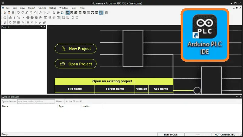
Start the Arduino PLC IDE software.
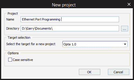
Start a new project. Enter the name and ensure that the target controller is the OPTA. Select OK.
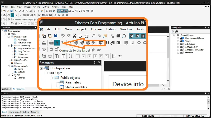
Connect to the Opta PLC.
This will upload the existing program that is in the OPTA and compare this to the program in the Arduino PLC IDE software.
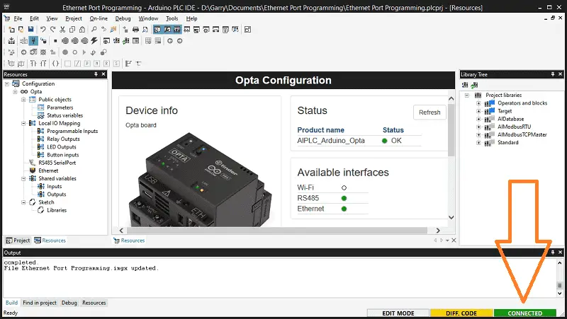
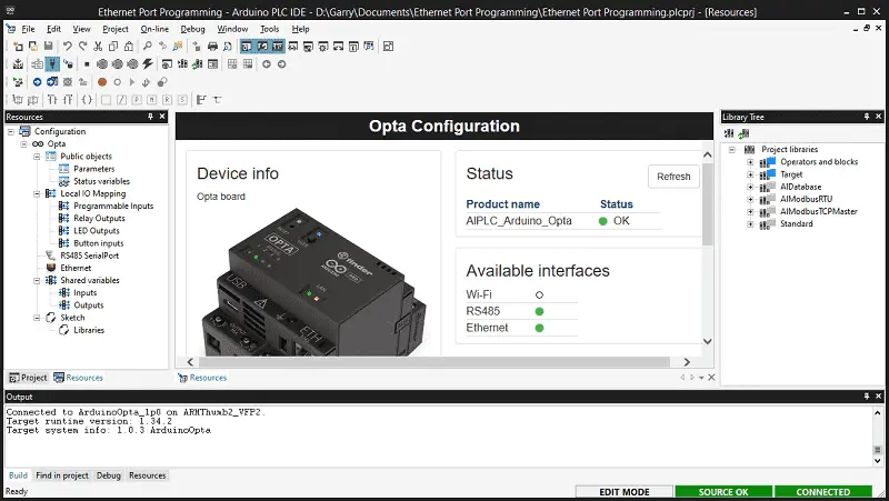
You will see that we are connected. The license and initial USB communication was established in a previous post. Once the license is established for the physical OPTA PLC controller, you will not have to do this again.
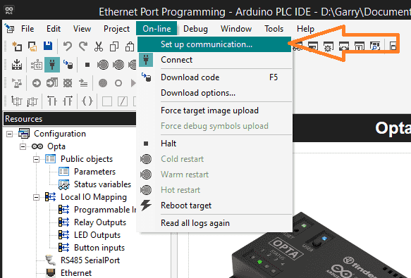
On the main menu, select On-line | Set up Communication…
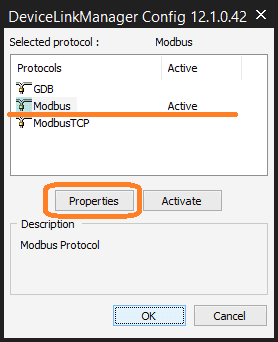
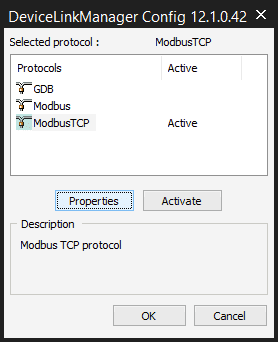
The device link manager config window will be displayed. Currently, we have Modbus active. This means that the serial port is used on the computer through the Arduino PLC IDE software to program the OPTA. Select the properties button for this connection.
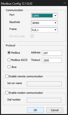
Make a note of the communication and protocol settings. These parameters must match if we need to return to this Modbus serial communication method. Select OK.
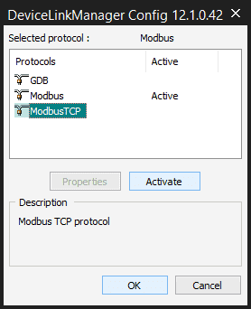
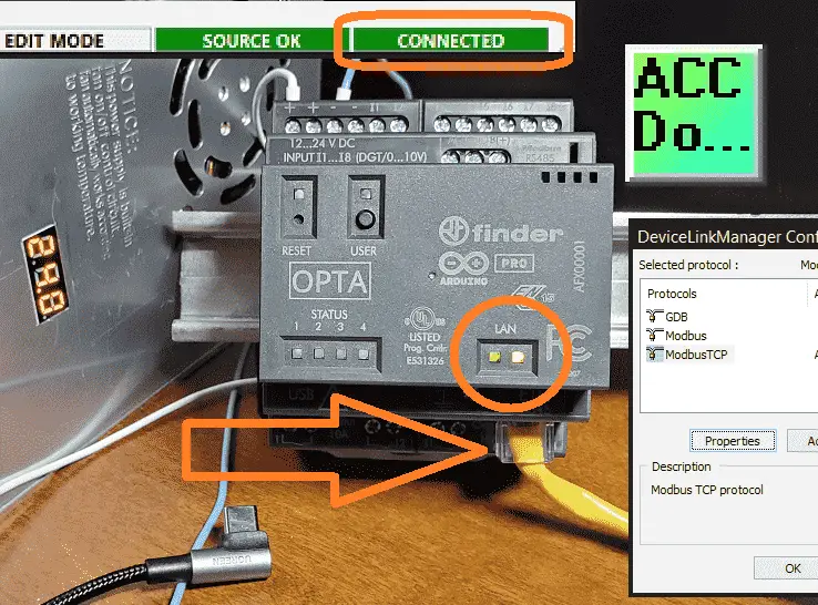
Select ModbusTCP on the device link manager configuration window. Press the activate button.
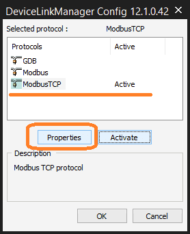
Our Modbus TCP (Ethernet) connection is now active. Select the Properties button.
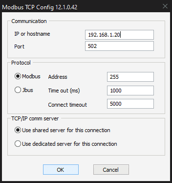
Enter the IP address of the OPTA IoT PLC that we determined previously. The default port number of Modbus TCP is 502. The Modbus address is 255, the highest address that can be used on our Ethernet network. This is similar to the maximum Modbus address 247 for the serial connection. We will leave the default of the shared server for this connection. Select OK.
Our Ethernet programming port has now been set for the OPTA PLC. Select OK.
We can disconnect the USB cable because we are now programming through the Ethernet port. Ensure you have a power supply connected to the Arduino OPTA to power up the controller.
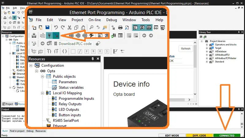
We can now compile and download the PLC code using Ethernet.
Watch the video below to see how to program the Opta IoT PLC through the Ethernet port using the Arduino PLC IDE.
Arduino Opta PLC – IoT and Industry 4.0 Enabler
Arduino Opto IoT PLC Series
Opta – Frequently Asked Questions (FAQ)
Finder OPTA 8A Series – Tutorials
Datasheet
Quickstart Sheet
Arduino Opta Hardware
Arduino PLC IDE
Arduino Software Download Page
(Arduino IDE, PLC IDE, PLC IDE Tools)
Watch on YouTube: Programming the Arduino OPTA PLC using Ethernet Port
If you have any questions or need further information, please contact me.
Thank you,
Garry
If you’re like most of my readers, you’re committed to learning about technology. Numbering systems used in PLCs are not challenging to learn and understand. We will walk through the numbering systems used in PLCs. This includes Bits, decimals, Hexadecimal, ASCII, and Floating points.
To get this free article, subscribe to my free email newsletter.
Use the information to inform other people how numbering systems work. Sign up now.

The ‘Robust Data Logging for Free’ eBook is also available for free download. The link is included when you subscribe to ACC Automation.