
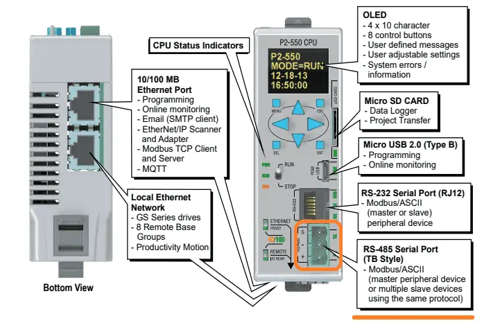
The Productivity 2000 series of PLCs has five built-in communication ports for easy connectivity to your PC or various industrial networks. Serial protocols like Modbus RTU can be utilized with the RS232 or RS485 ports on this PLC. Modbus RTU (Serial) is an open (published) protocol that uses the Master / Slave architecture. It’s a widespread protocol used in industrial automation controls.
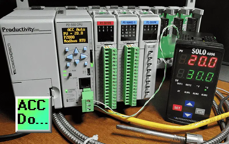
We will use the RS485 (2-wire) port to communicate to a Solo Process Temperature Controller. Modbus RTU will be the protocol used on this serial communication media. The P2000 PLC will be the master, and the Solo process temperature controller will be the slave. You will soon see how easily the Productivity Series of PLCs handles communication with other devices. Let’s get started.
Previously in this Productivity 2000 series PLC, we have discussed the following:
P2000 Hardware Features – Video
Productivity Suite Software Install – Video
Communication (System Configuration) – Video
First Program – Video
Debug Mode – Video
PLC Program Documentation – Video
PLC CPU Display – Video
PLC Online Programming – Video
PLC Tag Database – Video
Ladder Logic Contacts – Video
Ladder Logic Outputs – Video
Timers – Video
Counter – Video
Productivity 2000 PLC Ladder Logic Math – Video
Data Handling Instructions
Part 1 – Video
Part 2 – Video
Array Functions
Part 1 – Video
Part 2 – Video
Part 3 – Video
P2000 Program Control – Video
Drum Sequencer Instructions – Video
Data Logger and Logging – Video
Web Server (HTTP) – Video
Solo Process Temperature Controller Configuration – Modbus RTU
The first thing that we will do is set up the Solo Temperature Controller. Additional information can be found at the following link.
https://accautomation.ca/solo-process-temperature-controller/
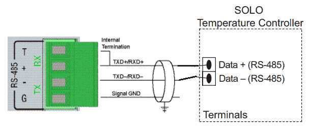
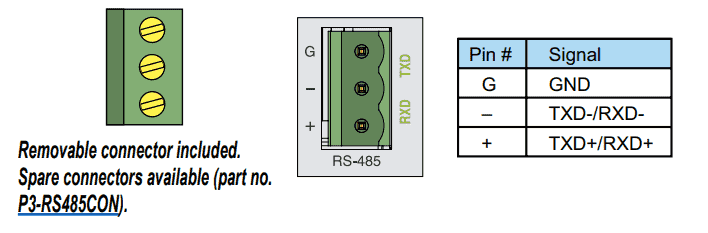
RS485 communication is established using a twisted pair of wires with a built-in termination resistor in the P2000 PLC. Additional devices can be added to the network by wiring them in parallel with the two wires.
Wiring diagram – Productivity 2000 to Solo – Serial RS485
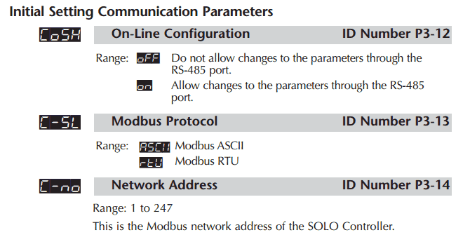
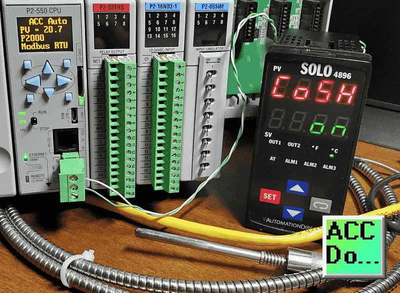
The solo process temperature controller must be set up before we can communicate with it. The default setting is ‘Off’ for the On-Line Configuration. Here is the way to change into the different modes in the Solo.
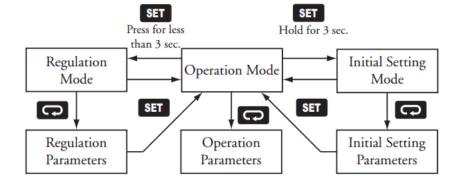
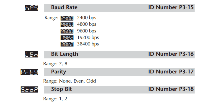
In the Initial Setting Mode, we will change the online configuration to “on” and make the changes to the Modbus settings as follows: 9600 Baud, Even, 7 Data Bits, 1 Stop Bit, and Modbus RTU Format. We will leave the default unit number as 1.
Our controller is now set to communicate.
Download the documentation and configuration, and monitoring software at the following URL link:
https://support.automationdirect.com/products/solo.html
Solo Process Temperature Controller Manual
https://cdn.automationdirect.com/static/manuals/solocontrolm/solocontrolm.html
Productivity 2000 Modbus Overview
Modbus RTU will be the serial (RS485) method to communicate between the Productivity 2000 PLC and the Automation Direct Solo Process Temperature Controller. This is a Master/Slave (Client/Server) protocol. The master sends a request, and the slave will respond to that request only. Here is an example of an RS485 Modbus RTU network.
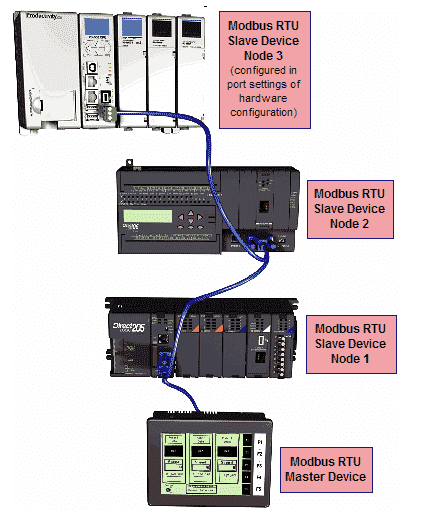
We can address up to 247 (Solo 1 to 247) devices on this master–slave protocol. A maximum of 32 devices (Nodes) on the network can communicate with the master. The Modbus RTU protocol can be reviewed at the following URL.
https://www.rtautomation.com/technologies/modbus-rtu/
Productivity 2000 Port Setup – Modbus RTU
The RS485 port must be set up the same as the port setup of the Solo Process Temperature Controller. Under the Setup in the Application Tools, select Hardware Config.
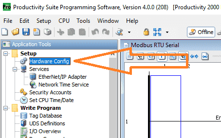
Alternatively, you can use the main menu | Setup | Hardware Config.
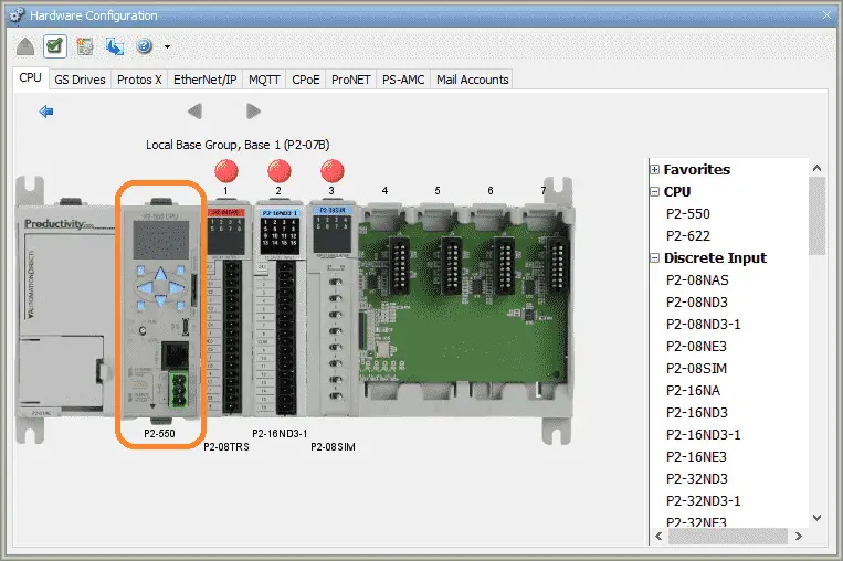
The hardware configuration window will now be displayed. Double-click on the CPU unit outlined in orange.
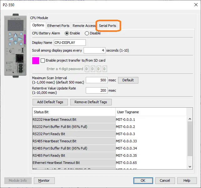
This will bring up the P2-550 CPU model window. Select the Serial Ports tab at the top of the screen.
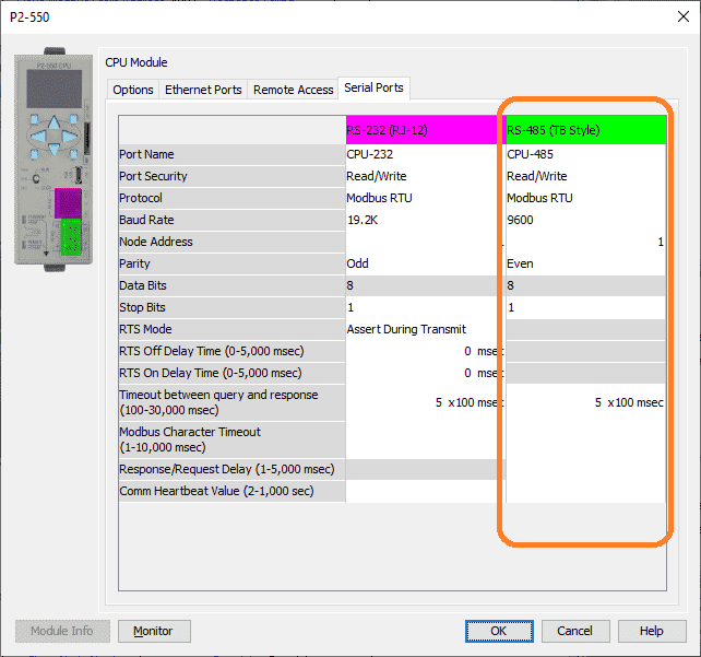
We will make our port settings match what we set on the Solo.
Protocol – Modbus RTU
Baud – 9600
Node Address – 1 – This is the same as the solo. Since this is the master, the number can be the same.
Parity – Even
Data Bits – 8
Stop Bits – 1
Ensure that port security is set for Read/Write. Select OK after setting these parameters.
Click the x on the hardware configuration window. We are now finished setting the port of the PLC for communication.
Productivity 2000 PLC Program – Modbus RTU Serial Communication
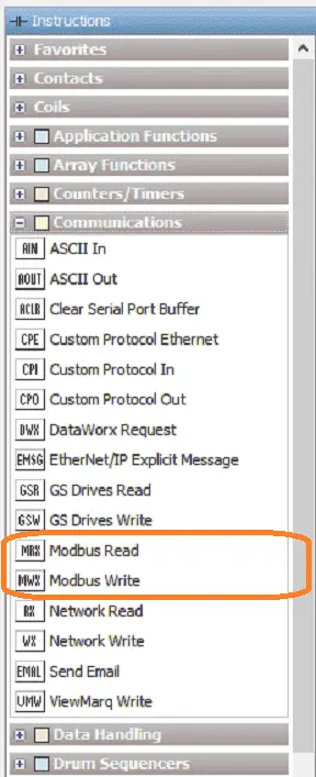
We will use the Modbus Read (MRX) and the Modbus Write (MWX) instructions for our Modbus RTU master program.
Modbus Read (MRX)
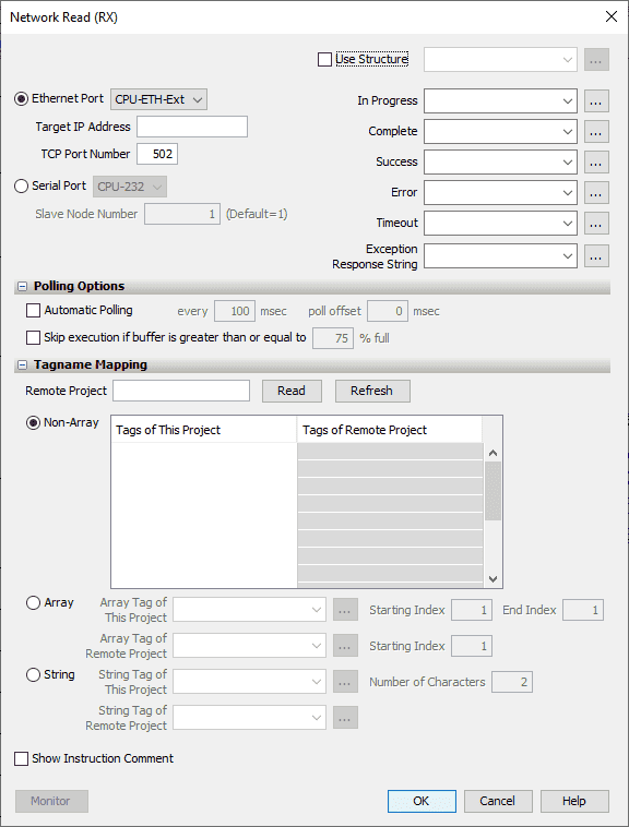
This instruction is broken down into three sections. The first is the instruction parameters.
Select the Serial Port – CPU485
Our slave node number for the Solo is 1.
We will use the structure with the name of Modbus_Read. This will set up the corresponding addresses and bits for this instruction.
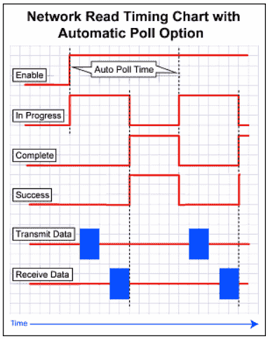
The second part is the addressing and polling options. This makes the setting of the Modbus Master the easiest that I have seen. The Automatic Polling feature allows you to choose the rate at which you desire to send messages without using a separate timer and enabling logic. The Message Queue stages the messages from the ladder code to go out to each physical communications port without requiring interlocking logic. The longer the poll time can be, within the application’s tolerance, the better the overall network performance. So for efficiency in programming and the best possible performance for the system, conservative poll rates should be used when utilizing the Automatic Poll feature. There is also a Poll offset field in the communications instructions. This helps prevent the instructions from being queued all at the same time. When the CPU project starts, there is a master timer that begins. The ladder scan will look to see if the instruction is enabled. If enabled, it will start the Automatic Poll timer at the specified poll offset value from the master time clock.
We will select automatic Polling at 100 milliseconds. This means that all of the timing between all of the Modbus Read and Write commands will be automatically handled by the PLC firmware.
Our Slave Modbus Starting Address is 4097. Note that the +400000 is added based on the Modbus Function Code selected.
We will be using Modbus Decimal Addressing.
The third part of the instruction is Tagname Mapping. This will specify where the information read is to be placed. We will create a Non-Array of 1 tag. Our Tag will be a 16-bit integer named Solo_PV. This will display the present value of our slave.
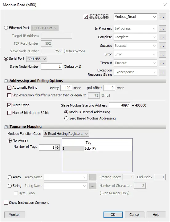
Here is our completed Modbus Read instruction.
Modbus Write (MWX)
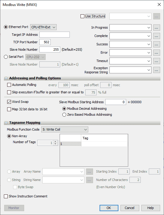
This instruction is broken down into three sections. The first is the instruction parameters.
Select the Serial Port – CPU485
Our slave node number for the Solo is 1.
We will use a structure with the name of Modbus_Write. This will set up the corresponding addresses and bits for this instruction.
The second part is addressing and polling options. Automatic Polling performs all of the sequencings for you, so you do not have to write any logic.

We will select automatic Polling at 100 milliseconds. This means that all of the timing between all of the Modbus Read and Write commands will be automatically handled by the PLC firmware.
Our Slave Modbus Starting Address is 4098. Note that the +400000 is added based on the Modbus Function Code selected.
We will be using Modbus Decimal Addressing.
The third part of the instruction is Tagname Mapping. This will specify where the information read is to be placed. We will create a Non-Array of 1 tag. Our Tag will be a 16-bit integer named Solo_SV. This will write the value of this register into our slave.
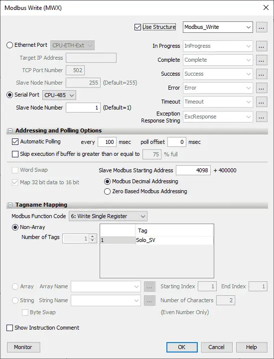
Here is our completed Modbus Write instruction.
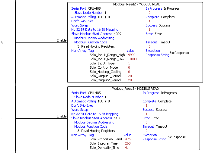
Additional Modbus Read (MRX) Instructions
Structure – Modbus_Read2
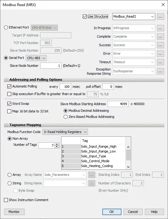
Automatic Polling will also be set up for reading the following Solo parameters.
Input Range High – 16-bit register
Input Range Low – 16-bit register
Input Type – 16-bit register
Control Mode – 16-bit register
Heating Cooling – 16-bit register
Output 1 Period – 16-bit register
Output 2 Period – 16-bit register
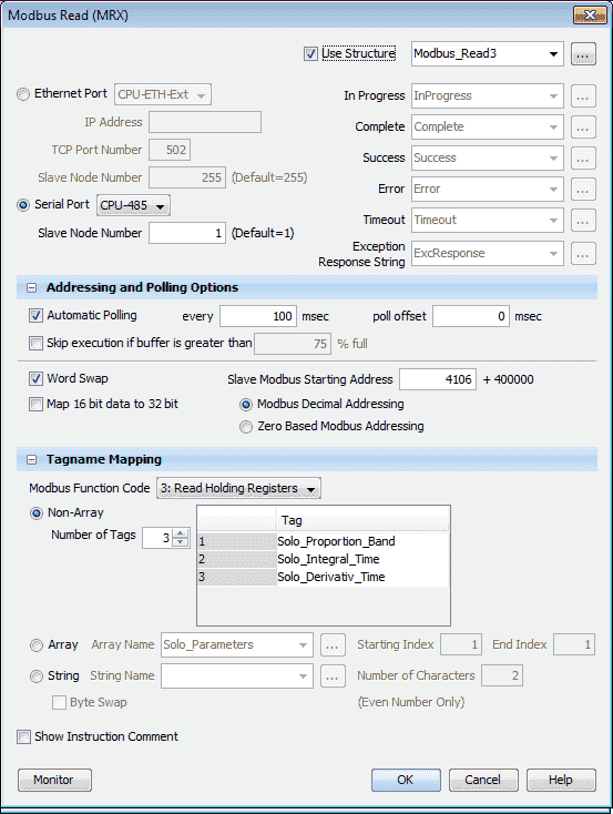
Structure – Modbus_Read3
Proportional Band – 16-bit register
Integral Time – 16-bit register
Derivative Time – 16-bit register
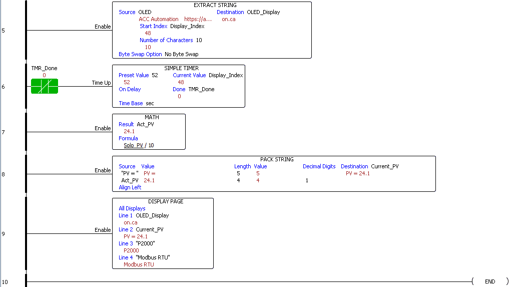
Here is our completed program:
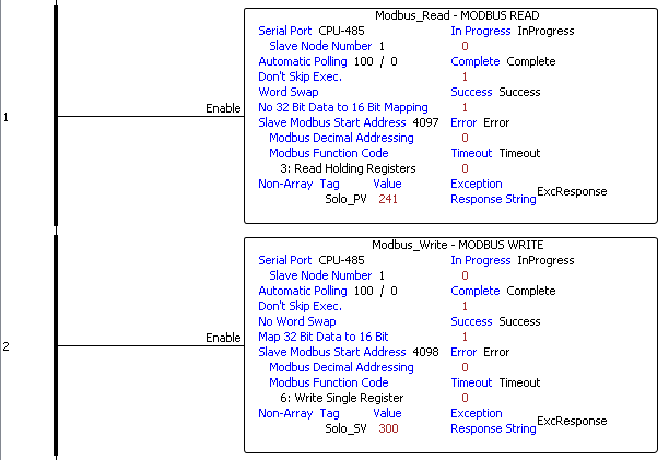
Note that the Modbus read and write instructions do not have any logic to enable them. They are always enabled because the automatic Polling will take care of the timing sequence for us. This makes the productivity series of controllers the easiest way to communicate Modbus.
Our program also will display the present value of the Solo temperature controller on the CPU display. The math instruction is used to convert the PV value to a float to get the decimal place. We then use the Pack String instruction to put together the string variable to display.
Monitoring our Modbus RTU Communication
We can use the Data View to monitor all the Solo process temperature controller tags. You can call the Data View from the Monitor & Debug under the Application Tools. Using the main menu | Tools | Data View or Ctrl + Shift + F3 will also bring up the Data View window.
We can change the SV of the Solo using our tag Solo_SV.
Calling the Graph View of the Data View will show us a graph of the variable that we select.
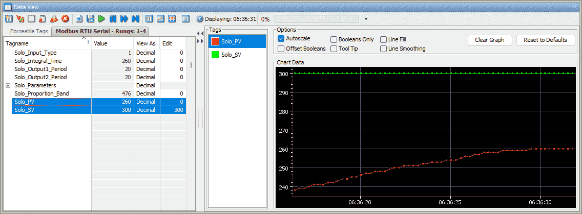
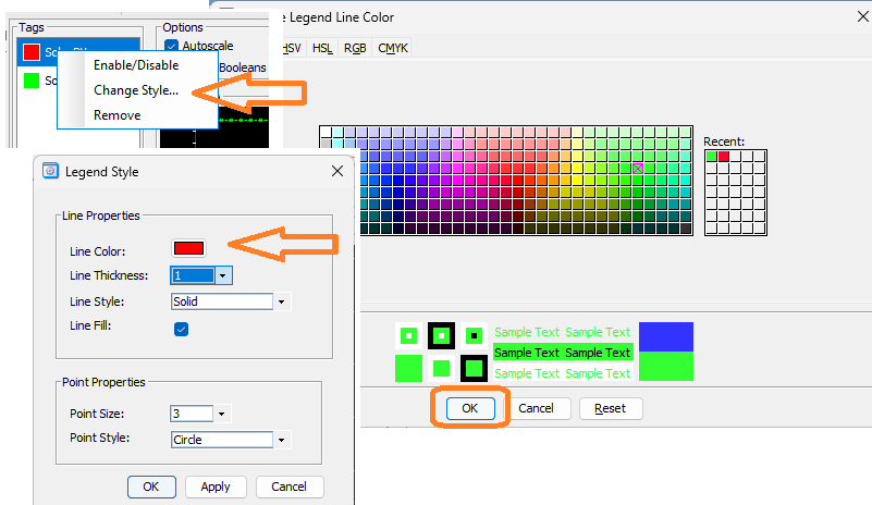
The legend color of the graph can be changed by right-clicking the variables monitored and selecting Line Color. Charts are a great way of troubleshooting your system.
Download the P2000 PLC program here.
Watch the video below to see the running and configuration of the Modbus RTU Serial Communication from the Productivity 2000 Series PLC to the Solo Process Temperature Controller.
Productivity 2000 Series PLC from Automation Direct
Overview Link (Additional Information on the Unit)
Configuration (Configure and purchase a system – BOM)
User Manual and Inserts (Installation and Setup Guides)
Productivity Suite Overview (Features of the fully functional free software package for the Productivity Family of PLC (PAC) controllers)
Productivity Suite Programming Software (Free Download Link)
This software contains all the instructions and helps files for the Productivity Series.
Watch on YouTube: Productivity 2000 Series PLC Modbus RTU Serial Communication
If you have any questions or need further information, please contact me.
Thank you,
Garry
If you’re like most of my readers, you’re committed to learning about technology. Numbering systems used in PLCs are not challenging to learn and understand. We will walk through the numbering systems used in PLCs. This includes Bits, decimals, Hexadecimal, ASCII, and Floating points.
To get this free article, subscribe to my free email newsletter.
Use the information to inform other people how numbering systems work. Sign up now.

The ‘Robust Data Logging for Free’ eBook is also available for free download. The link is included when you subscribe to ACC Automation.