We will now establish communication between the Arduino Opta IoT PLC and our computer. Every Opta IoT PLC comes with the ability to be programmed using the professional series Arduino PLC IDE. (Arduino PRO) This is designed to implement industrial machine control functions and programming, including ladder logic. The Opta hardware is also designed to support industrial voltages.
We will guide you through initializing and licensing the Opta IoT PLC. We will use the micro-C USB connector and the Arduino PLC IDE software to communicate with the Opta PLC. Furthermore, we will also demonstrate how to put the Opta PLC into bootloader mode to enable the use of Arduino IDE programs. Let’s get started. The entire Arduino Opta IoT PLC Series is located here.
Previously in this series, we have discussed the following:
Opta Introduction Video
Arduino Opta IoT PLC Cutting Edge Hardware – Video
Arduino Opta Software Installation – Video
Arduino Opta IoT PLC Quick Start Ladder Logic – Video
Note: A post is usually associated with each video. This will provide additional details and links discussed.
Connection to the Opta IoT PLC
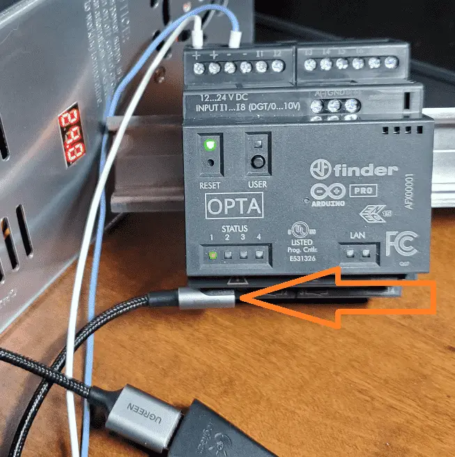
Power up your Arduino Opta IoT PLC using a power supply. (Power can also be applied to the CPU only through the USB cable.) Connect the Opta IoT PLC to our computer using a USB C to USB A cable. Plug in your cable.
NOTE: Not all USB C-type cables are the same. Some are just used for charging. Ensure that the cable used is also used for data.
Using the device manager in Windows, determine the communication port the Opta is connected to.
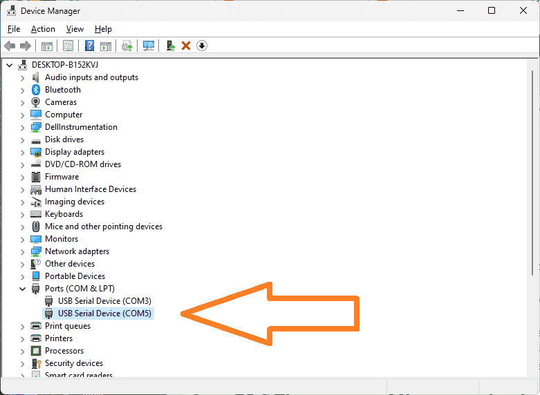
There are a few ways to show the device manager on a Windows 10 or newer computer. Right-click on the start menu or use Windows Logo + X. This will bring up a list that you can then select device manager. Another way is on the taskbar, in the Search field next to the Start button, type Device Manager and press Enter. There are more ways, but these are the quickest.
Opta PLC Firmware and license activation
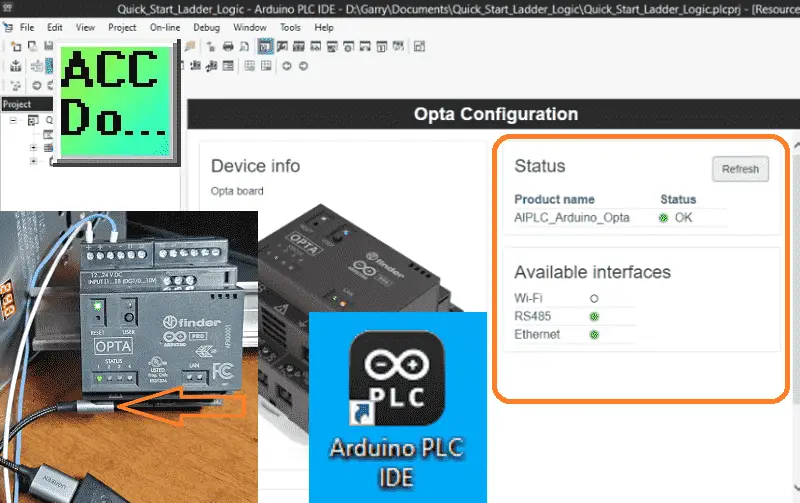
Start the Arduino PLC IDE software on your Windows 10 or newer software system using the icon created on your desktop.
Select a new project once the Arduino PLC IDE splash screen disappears and the program has started.
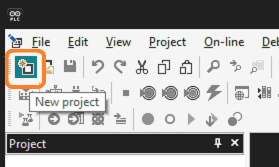
You can use the icon or select a new project from the file menu.
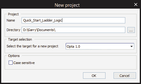
Enter the name of the new project. The directory where your project files will be stored can be changed. Our target is the Opta 1.0 which is the default selection. Select OK.
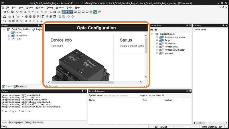
The Opta Configuration will now be displayed. You may have to scroll down and to the right to see all of the options. To the right under status it tells us to “Please connect to the target.”
Scroll down until you see the ‘Other’ selection. Select the port number that the Opta is connected to. Select the Download button.
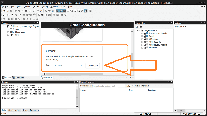
The firmware will be downloaded to the Opta, turning this controller into a PLC.
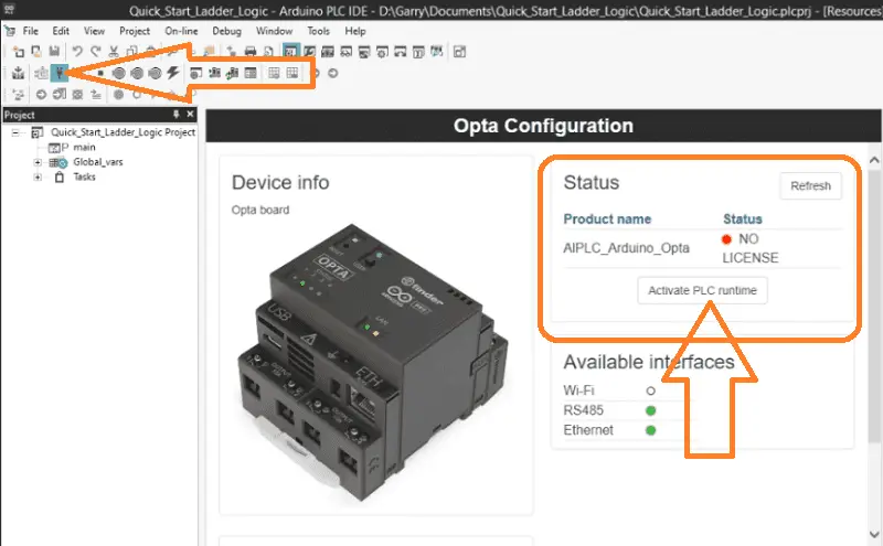
Click the Connect to Target icon in the main menu to confirm your connection to your Opta PLC. Under the status heading, you will see you do not have a license. Select the “Activate PLC runtime” option and follow the prompts to activate your PLC runtime.
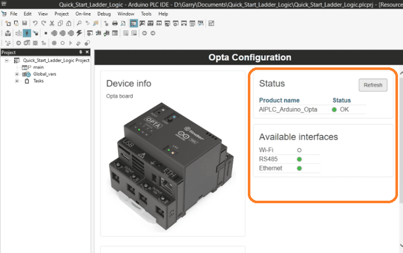
Make sure to disconnect the power to your Opta controller and USB cable before proceeding. Once you have restored power and reconnected the USB cable to the controller, click the refresh button in the status area.
Your Arduino Opta IoT PLC is now ready for you to start programming!
Note: The Arduino IDE and Arduino PLC IDE are different programming software packages. Only the Arduino PLC IDE software will allow the OPTA to run as a PLC.
Using Arduino IDE for Communication – Bootloader
Using the regular Arduino IDE software, you must activate bootloader mode to upload code to the Opta. Connect your Arduino Opta IoT PLC to your computer via a USB ‘C’ cable that can handle both power and data.
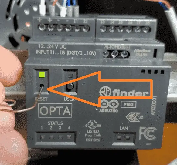
Simply double-tap the reset button on the Arduino OPTA PLC to activate bootloader mode, indicated by the CPU’s pulsing light. You can now proceed to download your program code.
Arduino Opta PLC – IoT and Industry 4.0 Enabler
Arduino Opto IoT PLC Series
Opta – Frequently Asked Questions (FAQ)
Finder OPTA 8A Series – Tutorials
Datasheet
Quickstart Sheet
Arduino Opta Hardware
Arduino PLC IDE
Arduino Software Download Page
(Arduino IDE, PLC IDE, PLC IDE Tools)
Watch on YouTube: Easy Steps to Establish Communication between Arduino Opta IoT PLC
If you have any questions or need further information, please contact me.
Thank you,
Garry
If you’re like most of my readers, you’re committed to learning about technology. Numbering systems used in PLCs are not challenging to learn and understand. We will walk through the numbering systems used in PLCs. This includes Bits, decimals, Hexadecimal, ASCII, and Floating points.
To get this free article, subscribe to my free email newsletter.
Use the information to inform other people how numbering systems work. Sign up now.

The ‘Robust Data Logging for Free’ eBook is also available for free download. The link is included when you subscribe to ACC Automation.