An ultrasonic sensor (switch) is able to detect object presence without physical contact (limit switch). No physical contact means that the switch has no parts that will wear out. The life span of the sensor is increased with less maintenance.
An ultrasonic sensor will use sound waves to detect objects. These sound waves are at a level that we cannot hear. Distance is measured by the time it takes to send and receive the ultrasonic wave. Objects can be measured the same no matter what the colour, transparency, shininess, or lighting conditions of the application.
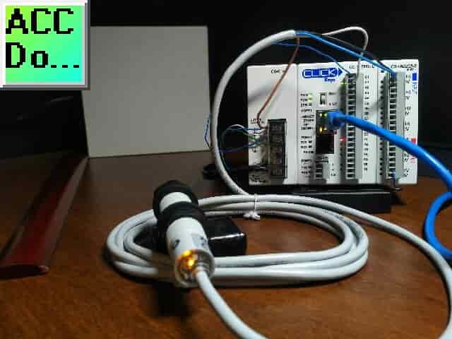
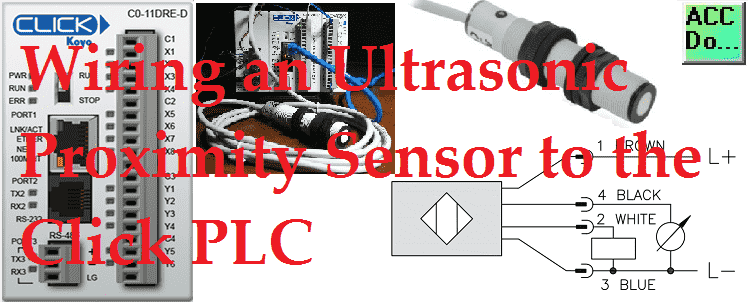
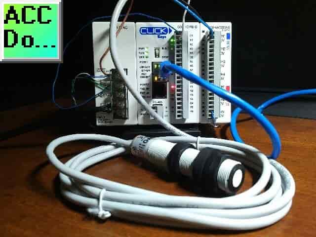
We will be wiring an ultrasonic sensor into the input of our Click PLC. This will include a discrete and analog input signal. The UK1F-E7-0A is an 18mm diameter sensor that has a PNP N.O./N.C. selectable output with analog output of 0 -10 VDC. The sensing distance is 200mm to 2200mm and has a one-hertz switching capacity. A 4-pin M12 quick disconnect is available but we will be wiring in our 2m wired version. Let’s get started.
Additional component connections to PLC include the following:
Here’s a Quick Way to Wire NPN and PNP Devices
– Wiring NPN Sensor to PLC Video
– Wiring PNP Sensor to PLC Video
– Wiring Contact Discrete PLC Inputs Video
Wiring Interposing Relays
– Wiring NPN and PNP Sensors into the PLC with an Interposing Relay Video
Click PLC HMI Rotary Encoder Dial Input – Video
Wiring Stack Light to Click PLC – Video
Wiring Push Buttons and Selector Switch to Click PLC – Video
– Test and Assembly of Push Buttons and a Selector Switch – Video
Wiring an Inductive Proximity NPN PNP Sensor to the Click PLC – Video
Wiring a Capacitive Proximity NPN PNP Sensor to the Click PLC – Video
Watch the video below to see the wiring of our PNP and Analog signal to the Click PLC with the ultrasonic switch.
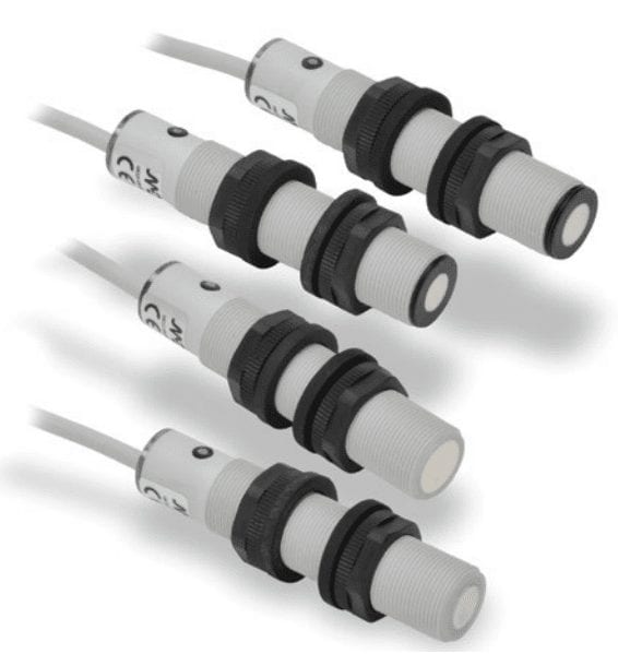
UK / SU Series Ultrasonic Proximity Sensors
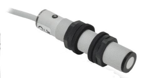
M18 (18 mm) plastic – DC
• High resolution
• 15 to 30 VDC operating voltage
• Discrete models available with adjustable sensitivity
• Analog output models available (0-10 VDC and 4-20 mA)
• Ten different output types: Single PNP, Single NPN, Dual PNP, Dual NPN, PNP & 4-20mA, NPN & 4-20mA, PNP and 0-10V, NPN and 0-10V, 4-20mA only, 0-10V only
• Sensing distances from 40 to 2200 mm
• Complete overload protection
• Multi-function LED status indicator
• Programmable via teach button or programmable via wire (UK6 Series)
• Mounting hex nuts included
• 2m output cable or M12 (12mm) quick-disconnect connector (purchase cable separately)
• CE, cULus file E187310, IP67 rated
• Lifetime warranty
UK1 Series Ultrasonic Specifications
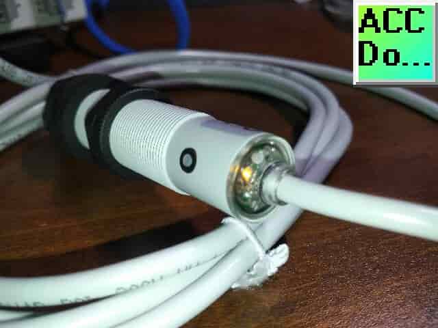
Watch on YouTube: Unboxing our UK1F Ultrasonic Proximity Sensor
Dimensions:
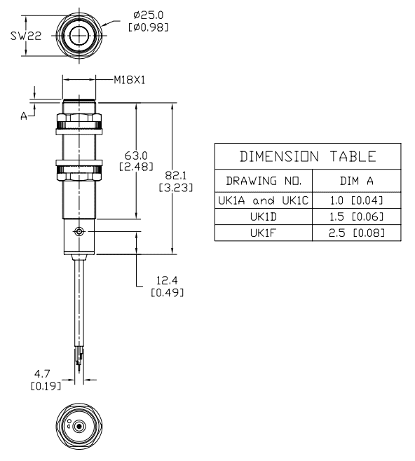
The sensor must be mounted 5mm from the edge of the face of the sensor. 5mm of the thread must be seen in order to not interfere with the sensor.
Ultrasonic Proximity Sensors
When looking at proximity sensors here are some terms that you need to understand.
Linearity Error
This is the deviation of the sensor output curve from a specified straight line. Our sensor has an error of <1%. This means that over the sensing distance from 200 to 2200 mm, we can be out by less than 1% or 22mm.
Switching Frequency
This is indicated in the specifications above and is expressed in hertz. Hertz is a measurement of pulses per second. In our case our sensor switching frequency is 1Hz. (1 time a second). In general, the larger the proximity sensor the slower the response.
Short Circuit and Reverse Polarity Protection
This will protect the sensor from incorrect wiring. It is a great feature of this ultrasonic proximity sensor.
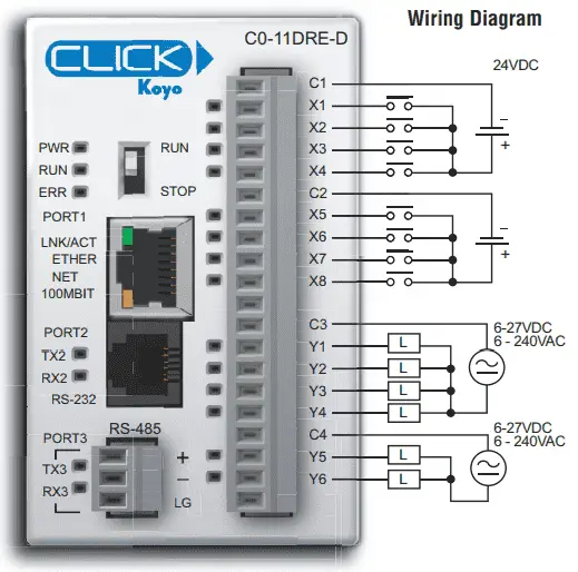
Wiring our Source Input
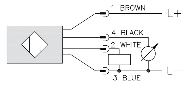
You can see that the inputs of the click can be wired with the common at +24VDC or 0VDC. The input of the PLC will act as the load for our ultrasonic proximity sensor discrete (on/off) input. This can be seen in the above diagram as a rectangular box.
PNP Wiring
This is sometimes referred to as sourcing the load or positive switching. The white wire of our sensor is connected to the PLC input (X1). The common point of the PLC input and the blue wire is connected to the 0VDC supply. The brown wire of our sensor is connected to the 24VDC supply. You can see that when the proximity switches, the sensor then connects the load to 24VDC.
Analog Wiring
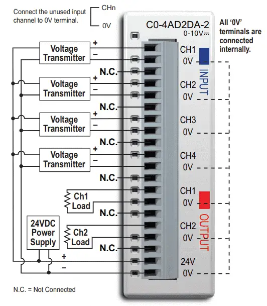
The analog input is shown in the diagram above as a circle with an arrow through it. This will indicate that the input is variable. In our case, our sensor is outputting 0 to 10 volts DC. Our black wire on our sensor will go to the first analog input point. (CH1) Since all of the ‘0V’ terminals are connected internally, our supply will already be connected to the 0VDC.
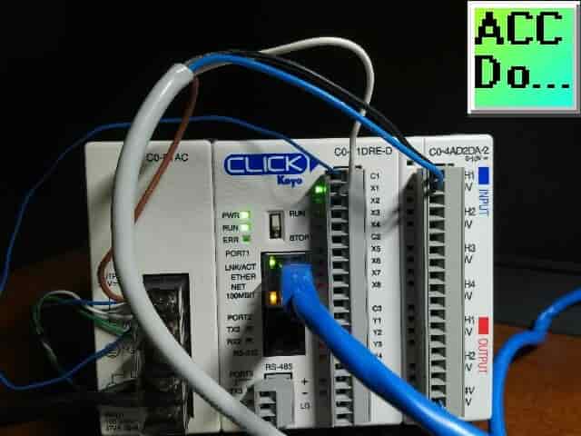
Watch the video below to see the wiring of our ultrasonic proximity sensor discrete and analog output into our Click PLC.
Target
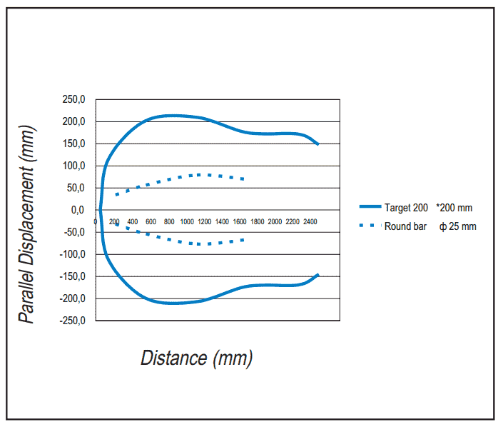
Our target (object) size that we can detect is specified in the chart above. The target can be 200mm or if a round bar is used 25mm.
Adjustment (Teach) Functions
The teaching function will allow the ultrasonic proximity sensor to learn the surroundings. It can be used to select the output mode like normally open (N.O.) or normally closed (N.C.). Teach is also used to set the analog output signal.
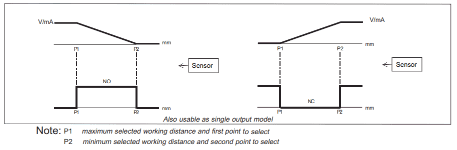
This sensor uses two points that must be programmed. (P1 and P2) P1 represents the position that will output 10V and P2 represents the position that will output 0V.
Teach Function
P1 – Place the target at the right distance for P1. Press the teach-in button for 1 second. The LED turns ON after a maximum of 2 seconds. The sensor will now have position P1. You can now move the target.
P2 – Place the target at the right distance for P2. Press the teach-in button. The LED turns OFF then blinks 5 times. The sensor will now have position P2.
Your sensor is now programmed.
Configuration of NO and NC States
Sensors come from the factory in their NO state. You can change the logical digital output state of the sensor by pushing the Teach in button for more than 8 seconds until the LED starts to blink fast. Release the Teach in button and the LED will blink slowly. When the LED stops blinking the digital output state is changed.
Watch the video below to see the teaching of our ultrasonic proximity sensor.
PLC Program
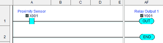
We will use a simple program in our Click PLC. When the normally open input (X1) proximity sensor is made, the output Y1 turns on.
The analog input is set up through the system configuration. Main Menu | Setup | System Configuration…
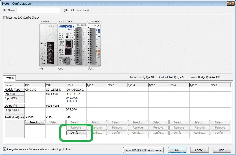
Under the analog input/output card select Config…
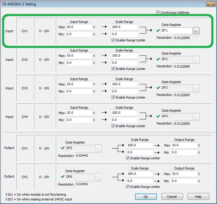
We can set the scaling parameters for our CH1 analog input. The sensor provides 0-10VDC we can let this represent actual units of measurement. In our case, we will set this to represent 0 to 100 %.
Monitoring the Click PLC Inputs and Outputs
If the PLC is in a panel and you cannot see the actual inputs and outputs (IO) there is a way to see the status lights. System Monitor is used to doing just that through the Click PLC software.
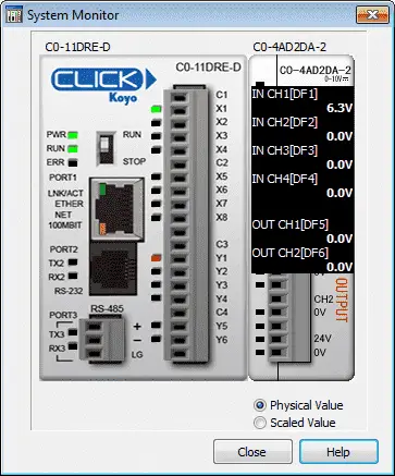
System Monitor can be accessed through the main menu | Monitor | System Monitor…
As we run our program the status of the PLC can be monitored.
Please watch the video below to see the wiring and operation of the ultrasonic sensor switch with the Click PLC.
Download the Click PLC program here.
UK1F Insert
UK1F-E7-0A
UK1 Series Ultrasonic Specifications
M12 quick-disconnect
Using the Teach Functions
Proximity Sensor Terminology
Sensors Frequently Asked Questions (FAQ)
Watch on YouTube: Wiring an Ultrasonic Proximity Sensor to the Click PLC
Here is some additional information on wiring PLC inputs.
Wiring NPN Sensor to PLC
https://youtu.be/Z09l3HKMpqs
https://accautomation.ca/heres-a-quick-way-to-wire-npn-and-pnp-devices/
Wiring PNP Sensor to PLC
https://youtu.be/nP33k5e_Y-k
https://accautomation.ca/heres-a-quick-way-to-wire-npn-and-pnp-devices/
Wiring Contact Discrete PLC Inputs
https://www.youtube.com/watch?v=xh5dE2Z09d0
https://accautomation.ca/how-plc-inputs-work/
Wiring Stack Light to Click PLC
https://accautomation.ca/wiring-stack-light-to-click-plc/
https://youtu.be/gwDIVtNSXfs
If you have any questions or need further information please contact me.
Thank you,
Garry
If you’re like most of my readers, you’re committed to learning about technology. Numbering systems used in PLC’s are not difficult to learn and understand. We will walk through the numbering systems used in PLCs. This includes Bits, Decimal, Hexadecimal, ASCII and Floating Point.
To get this free article, subscribe to my free email newsletter.
Use the information to inform other people how numbering systems work. Sign up now.

The ‘Robust Data Logging for Free’ eBook is also available as a free download. The link is included when you subscribe to ACC Automation.