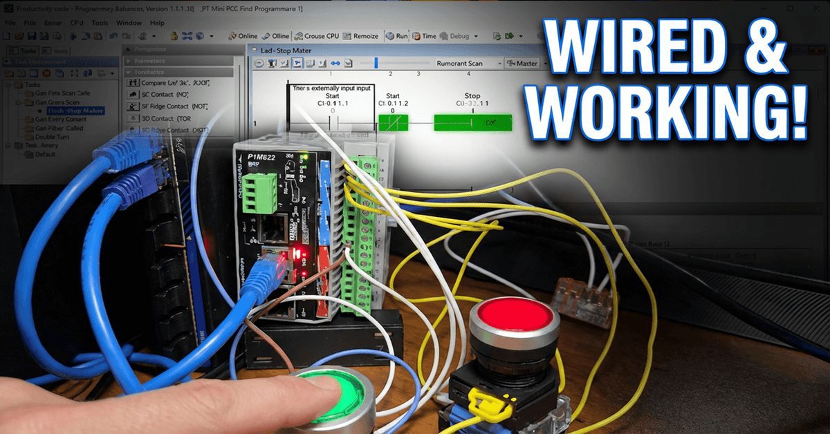
We will now look at wiring and testing our first ladder logic program with the P1-M622-16DR Mini PLC. Having created our start-stop motor circuit and learned about the monitoring tools in the Productivity Suite Software, it’s time to connect real-world devices and see our program in action. We will wire a start pushbutton, a stop pushbutton, and an LED to represent our motor output. Then we’ll systematically test everything—first in Stop mode to verify our wiring, then in Run mode to watch the ladder logic execute.
This is the exciting part where the software meets the hardware!
Let’s get started.
Previously in this Productivity Mini PLC P1-M622-16DR series, we have discussed:
P1-M622-16DR Mini PLC System Hardware – Video
Installing the Software – Video
Establishing Communication – Video
First Program – Video
Monitoring and Testing the Program – Video
Wiring and Testing – Video
Online Editing and Fail-Safe Wiring – Video
Understanding Our Circuit Wiring
Before we start wiring, let’s understand what we’re connecting and why. Our start-stop motor circuit uses:
Start Pushbutton – DI-0.1.1.1 – Normally Open
The start button is wired as a normally open (NO) contact. When you press it, it closes the circuit and sends a signal to the PLC input. In our ladder logic, we use a normally open contact instruction: when the physical button is pressed, the contact closes and allows power to flow through the rung.
Stop Pushbutton – DI-0.1.1.2 – Normally Open
Here’s where beginners often get confused. The physical stop button is wired as normally open, but in our ladder logic, we use a normally closed (NC) contact instruction. Why? We want to demonstrate that we can change the PLC’s logic. The stop input in our logic must remain active when no one touches it. This is why we use the normally closed contact in the program.
Note: Wiring a normally open stop pushbutton to any PLC is NOT a fail-safe design. If the wire breaks or comes loose, the circuit will not treat this as a “stop” condition and will not shut down the motor. We will change this in a later post.
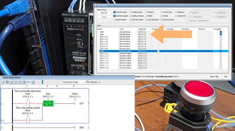
LED Light (Motor) – DO-0.1.1.1 The LED represents our motor contactor. When the PLC output turns ON, the LED illuminates—simulating the motor running. In a real application, this output would control a motor starter or contactor coil.
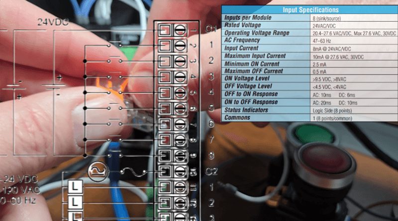
P1-M622-16DR Terminal Block Layout
The P1-M622-16DR uses an 18-position removable terminal block for field wiring. The terminal block accepts wire sizes from 30 to 16 AWG for solid conductors or 28 to 16 AWG for stranded wire. Strip length should be approximately 6 to 7mm.
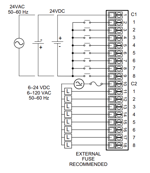
The terminal layout is arranged as follows:
Inputs (8 points):
- Terminals 1-8: Input points 1 through 8
- C1: Common for all 8 inputs
Power:
- Terminal marked “+”: 24VDC positive
- Terminal marked “-“: 24VDC negative (ground)
Outputs (8 points):
- Terminals for outputs 1 through 8
- C2: Common for all 8 relay outputs
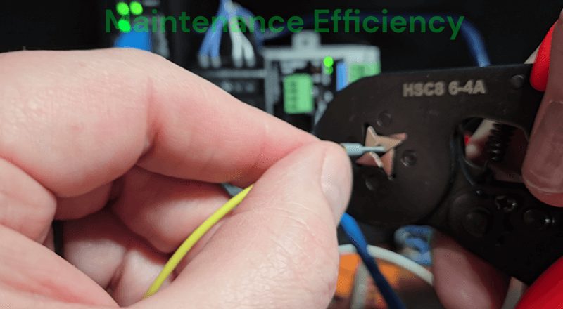
Why Use Ferrules?
We are using 20 AWG stranded wire. The use of ferrules is vital in industrial automation.
-
Vibration Resistance: In industrial environments, machinery vibration can cause bare stranded wire to fatigue and loosen over time. A crimped ferrule provides superior strain relief.
-
Optimal Conductivity: The crimping process deforms the wire and ferrule together, maximizing surface contact area and minimizing electrical resistance.
-
Maintenance Efficiency: Ferrules allow for repeated insertion and removal without degrading the wire end, making troubleshooting and field upgrades significantly faster.
-
Professional Standards: Using ferrules aligns with UL and IEC standards, ensuring the control cabinet meets the high-quality benchmarks required for modern automation systems.
Wiring the Start Pushbutton
The start pushbutton is a momentary, normally open switch. Here’s how to wire it:
- Connect one side of the pushbutton to the 24VDC positive supply
- Connect the other side of the pushbutton to Input 1 on the terminal block (DI-0.1.1.1)
- The input common (C1) should be connected to 24VDC negative (ground)
When you press the button, 24VDC flows through the closed contact to the input, which is registered as ON in the PLC.
Wiring the Stop Pushbutton
The stop pushbutton is also wired as a normally open momentary switch:
- Connect one side of the pushbutton to the 24VDC positive supply
- Connect the other side of the pushbutton to Input 2 on the terminal block (DI-0.1.1.2)
- The input common (C1) is already connected to ground from the previous step
Remember: Even though the physical button is normally open, the ladder logic uses a normally closed contact. When the button is NOT pressed, the input is OFF, but the NC contact in the ladder is TRUE (closed). When you press the stop button, the input turns ON, making the NC contact FALSE (open), which breaks the circuit and stops the motor.
Wiring the LED Output (Motor Indicator)
The LED represents our motor output:
- Connect the positive (anode) side of the LED to Output 1 on the terminal block (DO-0.1.1.1)
- Connect the negative (cathode) side of the LED to ground through a current-limiting resistor (typically 470Ω to 1kΩ for 24VDC). Since we are connecting to an LED module with a built-in resistor, we can connect directly.
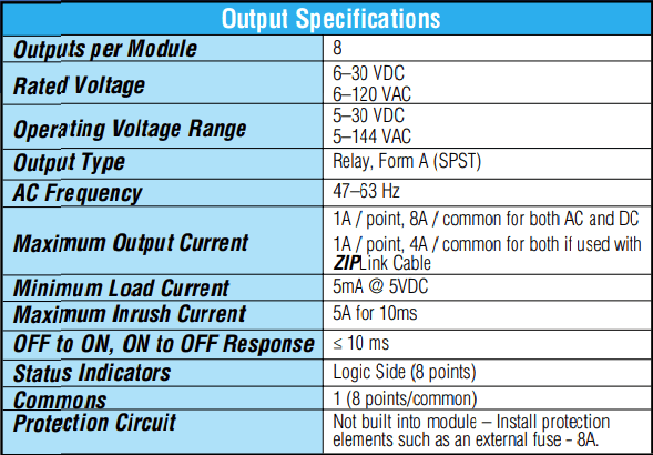
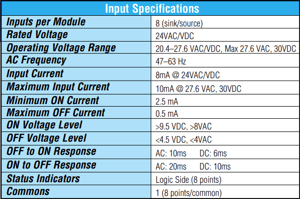
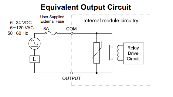
The P1-M622-16DR has relay outputs rated for 6-30VDC or 6-120VAC at 1A per point. For our LED test, we’re well within the specified limits.
Important: The relay outputs are Form A (SPST) contacts. You need to provide your own external power source for the output devices—the relay simply switches this power on and off.
Complete Wiring Summary
Here’s our complete wiring list:
| Device | PLC Terminal | Wire Connection |
|---|---|---|
| 24VDC Power + | + Terminal | Power Supply Positive |
| 24VDC Power – | – Terminal | Power Supply Negative |
| Start Pushbutton | Input 1 (DI-0.1.1.1) | One side to +24V, other to Input 1 |
| Stop Pushbutton | Input 2 (DI-0.1.1.2) | One side to +24V, other to Input 2 |
| Input Common | C1 | Connect to 24VDC Negative |
| LED Positive | Output 1 (DO-0.1.1.1) | LED Anode |
| LED Negative | C2 or Ground | LED Cathode (through resistor) |
| Output Common | C2 | Connect to power for output circuit |
Testing in PLC Stop Mode
Before we run our program, we need to verify that all wiring is correct. This is a critical step that many beginners skip—don’t make that mistake! Testing in Stop mode lets us check our I/O without running the program.
Step 1: Put the PLC in Stop Mode
Turn the CPU selector switch to the STOP position. The RUN LED on the CPU should turn off.
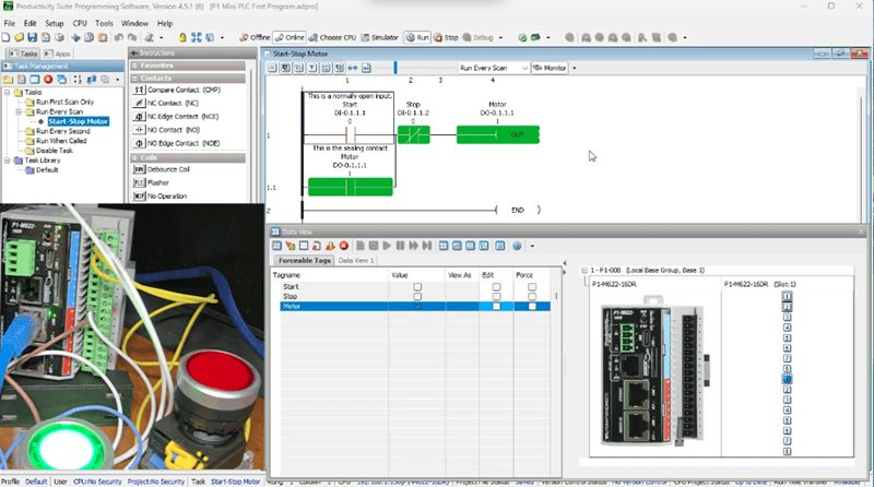
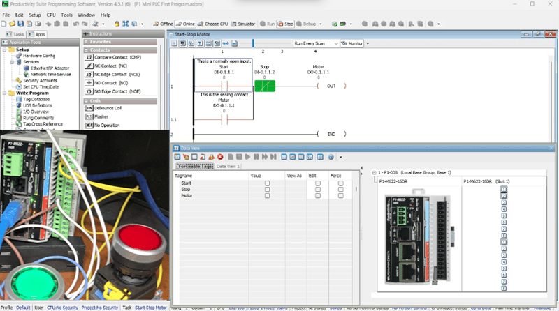
Step 2: Open Data View
In Productivity Suite, open the Data View panel (Tools | Data View or Ctrl + Shift + F3). You can also use the IO View for a graphical representation of all inputs and outputs.
Step 3: Test Input 1 (Start Pushbutton)
Press and hold the Start pushbutton. Watch the Data View—DI-0.1.1.1 should change from OFF (unchecked) to ON (checked). The input LED on the PLC front panel should also illuminate. Release the button and verify it returns to OFF. This confirms your Start button wiring is correct.
Step 4: Test Input 2 (Stop Pushbutton)
Press and hold the Stop pushbutton. Watch DI-0.1.1.2 in Data View—it should change from OFF to ON. Release and verify it returns to OFF. In the Ladder Logic, the stop will change from ON to OFF when the normally closed contact is pressed. When we release the stop button, the Ladder Logic contact returns to ON. This confirms your Stop button wiring is correct.
Step 5: Force the Output to Test LED Wiring
Now we need to test the wiring for our output. Since we’re in Stop mode, the program isn’t running, so we’ll manually force the output ON.
- In Data View, find DO-0.1.1.1
- Check the Edit checkbox
- Check the Force checkbox
- Check the Value checkbox to set it ON
- Click the Send Edit(s) button
The LED will not illuminate! However, the ladder logic will show that the output will be on. So we can only check the outputs when running our program.
When a Productivity PLC is in STOP mode, the CPU stops scanning the application logic. Consequently, output modules are typically set to a safe state (usually OFF) to prevent unintended machine operation.
If we need to check each output separately, we can use the END statement after each one. The program will scan only until the END statement, then return to the start of the ladder logic. As each output is confirmed, we can remove the END statements.
Step 6: Remove the Force
Uncheck the Force checkbox for DO-0.1.1.1 and click Send Edit(s) to remove the force. The LED should turn off.
Testing in PLC Run Mode
Now that we’ve verified all our input wiring is correct, let’s run the program and watch the ladder logic execute.
Step 1: Put the PLC in Run Mode
Turn the CPU selector switch to the RUN position. The RUN LED on the CPU should illuminate green.
Step 2: Enable Monitoring in the Ladder Editor
Ensure you click the Monitor icon in the task window toolbar. Your ladder logic will now show real-time states with green (ON) and red (OFF) indicators.
Step 3: Open Data View IO
Keep the Data View panel open so you can see the tag values change in real-time alongside the ladder logic.
Step 4: Test the Start-Stop Sequence
Test the Start Function:
- Press the Start pushbutton
- Watch DI-0.1.1.1 turn ON (green) in the ladder and Data View
- The output DO-0.1.1.1 should turn ON
- The LED should illuminate
- Release the Start button
- The output should STAY ON because of the sealing contact
Test the Seal Circuit: With the motor running (LED on), observe the ladder logic. You’ll see:
- DI-0.1.1.1 (Start) is OFF (red) because you released the button
- DO-0.1.1.1 (Seal contact) is ON (green)—this is keeping the circuit energized
- DI-0.1.1.2 (Stop NC contact) is TRUE (green) because the stop button is not pressed
- DO-0.1.1.1 (Motor output) is ON (green)
Test the Stop Function:
- Press the Stop pushbutton
- Watch DI-0.1.1.2 turn ON in Data View
- The NC contact in the ladder opens (turns red)
- The output DO-0.1.1.1 turns OFF
- The LED turns off
- Release the Stop button
- The motor stays OFF until Start is pressed again
Understanding What You’re Seeing
As you test, pay attention to these key observations:
The Seal Contact in Action: When you press Start momentarily, the motor turns on and stays on. This is because the output (DO-0.1.1.1) feeds back as a parallel contact with the Start button. Once the output is ON, it holds itself ON—this is called a “seal” or “latch” circuit.
The NC Stop Contact: The Stop button uses a normally closed contact in the ladder, even though the physical button is normally open. Watch what happens:
- Stop NOT pressed: Input is OFF, but NC contact is TRUE (closed)—allows current flow
- Stop pressed: Input is ON, NC contact is FALSE (open)—breaks the circuit
The Priority of Stop Over Start: Try this: Hold both buttons at the same time. The motor will NOT run. Stop always wins because the NC contact is in series with the circuit. This is intentional safety design.
Troubleshooting Common Issues
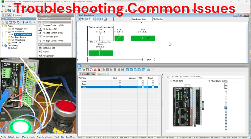
LED doesn’t light when forced (Run Mode):
- Check your wiring polarity (LEDs are polarized)
- Verify the current-limiting resistor value
- Confirm that the output common has a return path to ground
Input doesn’t register when the button is pressed:
- Verify 24VDC is present at the button
- Check the common (C1) connection to ground
- Inspect wire connections at the terminal block
Motor starts but won’t seal:
- Verify the seal contact address matches the output address
- Check that the output is actually turning on (watch the LED)
Motor won’t stop:
- Verify the Stop button is wired to the correct input
- Confirm the ladder uses an NC contact for Stop
- Check for a stuck Start button
Watch the video below to see how we wire and test our first program on the Productivity Mini PLC P1-M622-16DR.
Productivity Mini PLC P1-M622-16DR from AutomationDirect
Overview Link (Additional Information on the Unit) Configuration (Configure and purchase a system – BOM) User Manual and Inserts (Installation and Setup Guides) Productivity Suite Programming Software (Free Download Link)
This software includes all instruction sets and help files for the Productivity Series.
Next time, we will look at using online editing (Programming) to modify our program with or without the PLC running.
The Productivity Mini PLC series from AutomationDirect, and specifically, the P1-M622-16DR, is a compact powerhouse that packs serious capability into a surprisingly small footprint. To see our first ladder logic, click here. Click here to build digital twins of 3D virtual machinery, test control logic, and learn automation without expensive hardware, using Machine Simulator.
Watch on YouTube: Wiring and Testing Our: P1-M622-16DR Practical Tutorial!
If you have any questions or need further information, please contact me. Thank you,
Garry
Related Posts:
- How to Make a Start-Stop Jog Circuit in a PLC
- P1-M622-16DR Mini PLC Monitoring and Testing the Program
- Stop Struggling! Master Productivity 1000 PLC Debugging Tools
There are many PLC manufacturers offering various hardware and software. All programmable logic controllers share similar basic features. Here is how I would approach learning about basic PLCs.
Once you are familiar with the basics of the PLC, you will learn the specifics of the controller you will be programming.
This is the easiest way to learn about PLC programming.
Here are the controllers that we have covered or are covering at ACC Automation:
LS Electric XGB PLC Series
BRX Do-More Series (Do-More Designer Software + Simulator)
Productivity Series P1000 / P2000
Click PLC Series
Omron CP1H Series
Horner XL4 PLC Series
Arduino Opta PLC
The EasyPLC Software Suite is a comprehensive package that includes PLC, HMI, and machine simulator software. This allows you to make a digital twin. See below to receive 10% off this software. This PLC learning package contains the following:
Easy PLC – PLC Simulation will allow programming in Ladder, Grafcet, Logic Blocks, or Script.
HMI System – Easily create a visual human-machine interface (HMI)
Machine Simulator – A virtual 3D world with real-time graphics and physical properties. PLC programs can be tested using the EasyPLC or through other interfaces. (Modbus RTU, TCP, etc.)
Machine Simulator Lite – Designed to run on Android Devices.
Machine Simulator VR – Virtual Reality comes to life so you can test, train, or practice your PLC programming.
Purchase your copy of this learning digital twin package for less than $95 USD for a single computer installation or less than $110 USD to allow access on multiple computers.
Receive 10% off the investment by typing in ACC in the comment section when you order.
Learn PLC programming the easy way. Invest in yourself today.
Examples of PLC program development using the five steps.
Click PLC – Easy Transfer Line Programming – Video
Productivity PLC Simulator – Chain Conveyor MS – Video
Five Steps to PLC Program Development – Die Stamping
PLC Programming Example – Process Mixer
PLC Programming Example – Shift Register (Conveyor Reject)
PLC Programming Example – Paint Spraying
PLC Programming Example – Delay Starting of 7 Motors
PLC Programming Example – Pick and Place
PLC Programming Example – Sorting Station (Shift Register)
PLC Programming Example – Palletizer
If you’re like most of my readers, you’re committed to learning about technology. The numbering systems used in PLCs are not difficult to understand. We will walk through the numbering systems used in PLCs. This includes Bits, Decimals, Hexadecimal, ASCII, and Floating Points.
To get this free article, subscribe to my free email newsletter.
Use the information to educate others on how numbering systems work. Sign up now.

The ‘Robust Data Logging for Free’ eBook is also available as a free download. The link is included when you subscribe to ACC Automation.