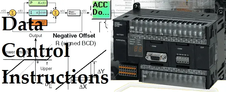
The data control instructions in the Omron CP1H programmable logic controller are used to manipulate the outputs based upon control conditions. Control is the main purpose of these instructions within the PLC. Instructions include PID (Proportional, Integral, and Derivative), PID with Autotuning, Dead Band Control, Limit, Dead Zone Control, Time Proportional Output, Scaling, etc.
We will be looking at some of these instructions in the Omron CP1H PLC. Examples of the instructions will be presented.
Previously in this CP1H series, we have discussed:
System Hardware – Video
CX-Programmer – Video
Establish Communication – Video
Setting, Forcing, and Online Editing – Video
Numbering System and Addressing – Video
CP1H Timers – Video
Counters – Video
Data Movement – Video
Compare Instructions – Video
Data Shift Instructions
– Video Part 1
– Video Part 2
Math Instructions – Video
Data Conversion – Video
Program Control Instructions – Video
Table Data Instructions – Video
Data Control Instructions – Video
AdvancedHMI Communication – Video
Several different program control instructions are available in the CP1H. A full explanation can be obtained by using the help menu in the CX-Programmer software or the Programming Manual for the CP1H. Links are provided at the end of this post.
Instructions can have different variations.
Let’s look at when this instruction will execute:
SCL(194) when used will be scanned and executed every cycle of the PLC that the input condition is on.
@ SCL(194) when used will be executed when the input condition turns from off to on. This will trigger the instruction to happen only once.
Please refer to the programming manual or help file in CX-Programmer for different variations of the instructions that you want to use. We will now go over some of the data control instructions in the Omron CP1H. This will give you a general idea of the instructions available.
Data Control Instructions – Omron CP1H
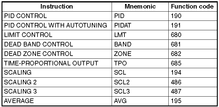
This list gives you all of the data control instructions in the CP1H. A lot of these instructions will only work with equipment wired into the controller to see the functionality. We will be looking at some of these instructions. An explanation will be given to the instructions that need additional equipment to properly demonstrate.
PID Control – Omron CP1H
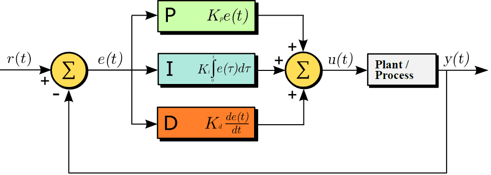
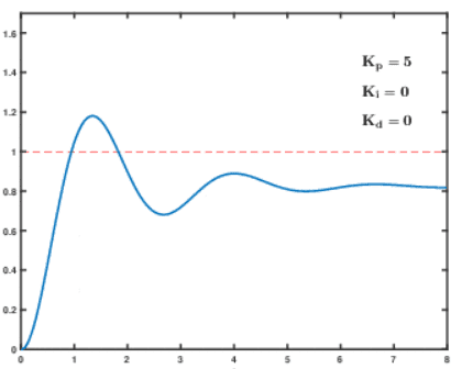
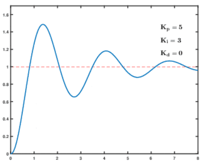
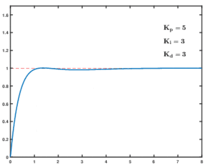
The first two instructions will deal with PID control. PID Control will calculate an error e(t) as the difference between the setpoint (r(t)) and a measured process variable (y(t)). It applies a correction factor based on proportional, integral, and derivative terms.
https://en.wikipedia.org/wiki/PID_controller
A PID control algorithm is based upon time. It controls the output in order to reach the setpoint without overshooting or undershooting the system.
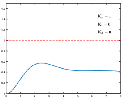
The following link will show you the effect of P, I, and D separately on the control system.
https://en.wikipedia.org/wiki/File:PID_Compensation_Animated.gif
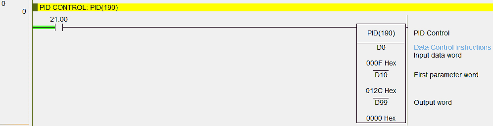
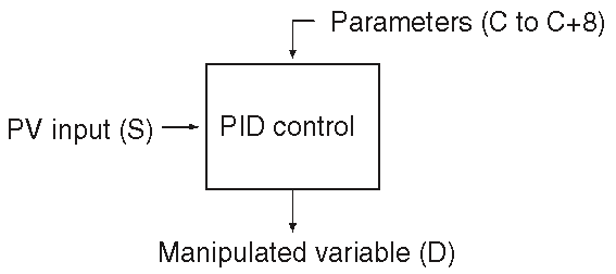
PID CONTROL: PID(190) – Omron CP1H
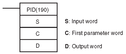
This instruction executes PID with two degrees of freedom. The parameters that you specify are used to perform this operation. All of the parameters are in hexadecimal. (Binary)
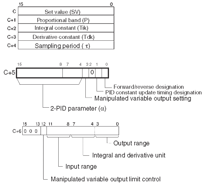
The input is read and based upon the parameters that are set, the manipulated value is outputted.

If the settings are set within the permissible range, PID will be executed. This instruction will not perform a ‘bumpless’ transfer. A bumpless transfer is an output that gradually and continuously changes the manipulated variable to avoid sudden changes. Complete instruction information can be obtained in the instruction manual for the controller.
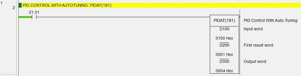
PID CONTROL WITH AUTOTUNING: PIDAT(191) – Omron CP1H
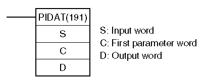
This instruction will execute the PID similar to the above instruction, however, the PID constants can be autotuned. This means that when autotuning is activated, the feedback from two cycles of the control (Above and Below Set Value (SV)) will be used to set the PID.
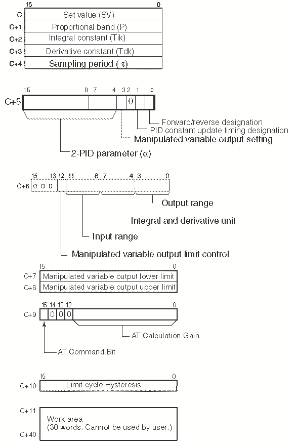
Parameters must be set in the controller (Binary) for the instruction to operate. Here is the control diagram for the instruction.
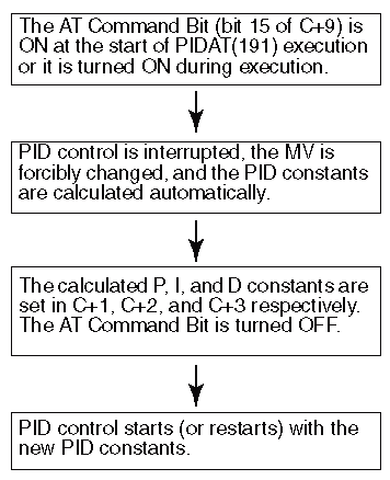
The autotune of the instruction has the following logic sequence.
LIMIT CONTROL: LMT(680) – Omron CP1H
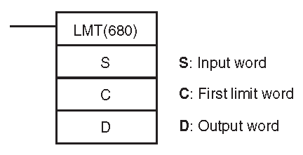
This instruction will control the output data according to whether or not the input data is within upper and lower limits.
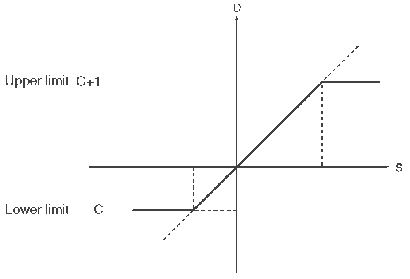
The limits are set in the first two registers specified. They are in binary format. The following flags will be available in your program after the execution of this instruction.

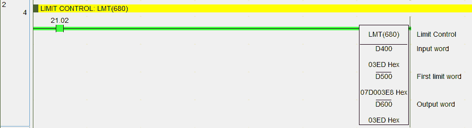
In our example the input is within the limits so the value is passed to the output. If the input is higher than the high limit, the high limit is passed to the output. If the input is lower than the low limit, the low limit is passed to the output. Flags are set as indicated above for each condition.
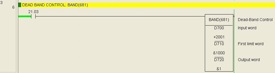
DEAD BAND CONTROL: BAND(681) – Omron CP1H
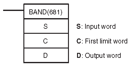
The output data is zero when the input data is within the lower and upper limits of the range. (Dead Band Range)

We specify the lower and upper limit words for this instruction.
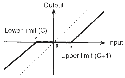
In our example when the input is within the upper and lower limits the output will be zero. When it is outside of these limits the output will show the amount that it is out.
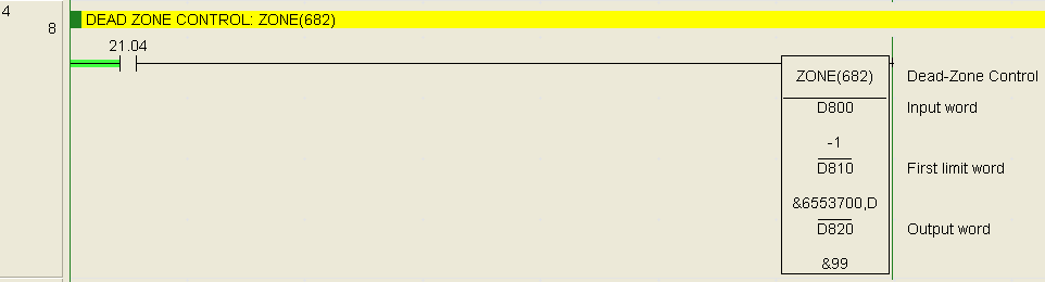
DEAD ZONE CONTROL: ZONE(682) – Omron CP1H
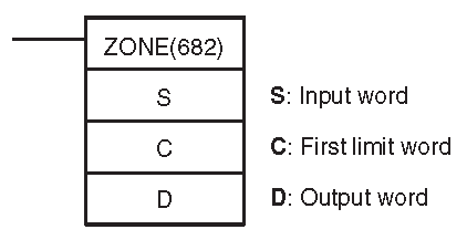
Adds the specified positive and negative bias to the input data and outputs the result.


If the input is positive, the positive bias is added to the output. If the input is negative then the negative bias is added to the output.
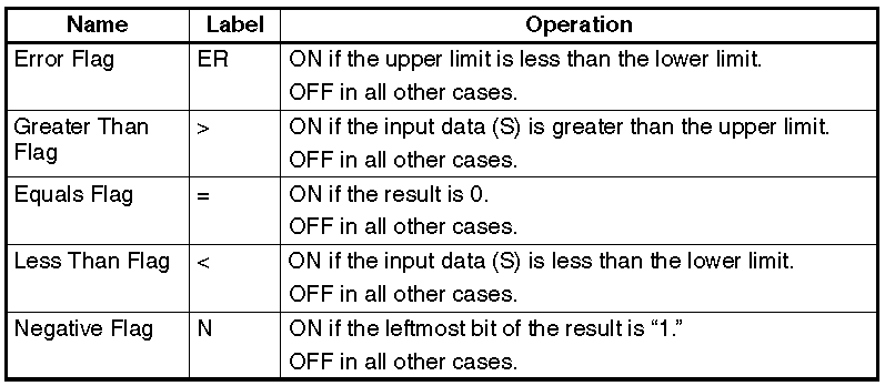
Flags are associated to this instruction as per the following table.
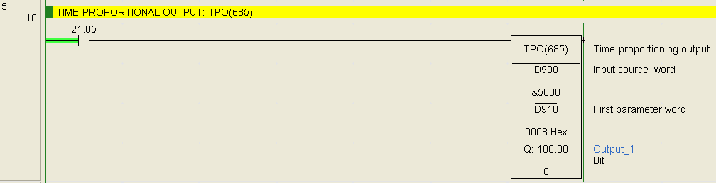
TIME-PROPORTIONAL OUTPUT: TPO(685) – Omron CP1H
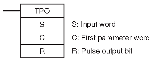
This instruction will take the input as either a duty ratio or manipulated variable (PID output) from the specified word, converts the duty ratio to a time-proportional output based on the specified parameters. This is then sent to the specified output bit.
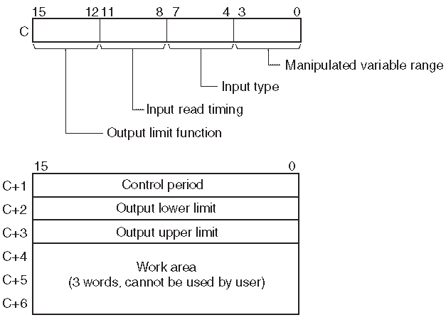
Here are the parameters.
Most time this is used in conjunction with the PID instruction as per the following diagram.

In our example, we are just using the instruction as a duty ratio on the output.
D910 – 0008 hex – Output Limit Disabled, Input read timing set to the beginning value of the control period, Duty ratio, 16-bit range
D911 – 01F4 hex – Control Period – 0064 to 270F hex (1.00 to 99.99 seconds)
The following chart explains the parameter settings.

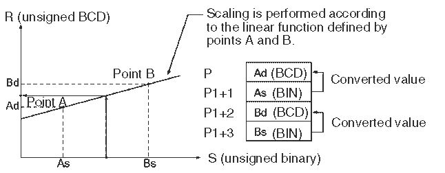
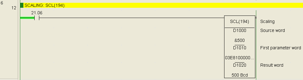
SCALING: SCL(194) – Omron CP1H
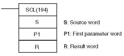
This instruction will convert an unsigned binary data into unsigned BCD data accoutring to the specified linear function.
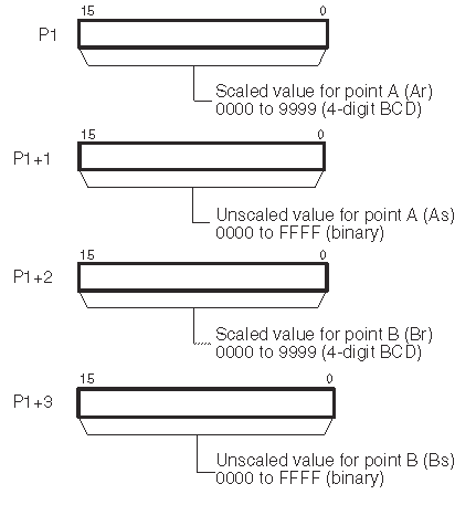
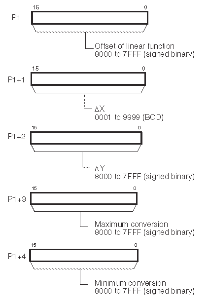
The parameters specify the linear line.
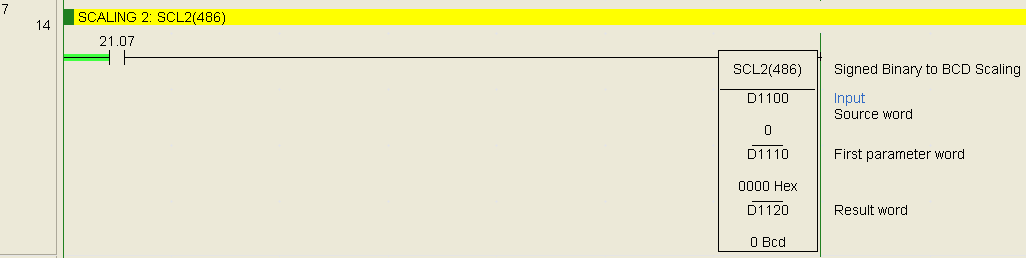
SCALING 2: SCL2(486) – Omron CP1H
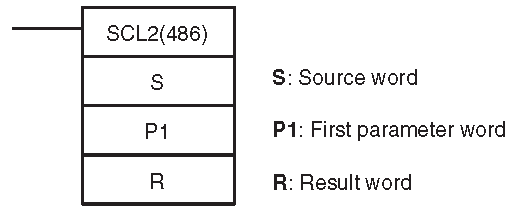
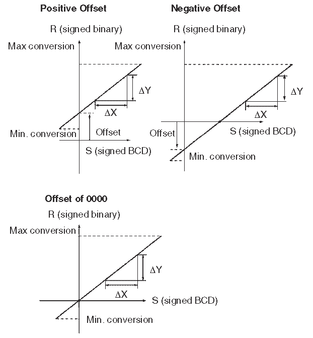
The instruction will convert a signed binary data into BCD data according to the specified linear function. An offset can be also defined in the linear function.


The slope of the line is Delta Y / Delta X.
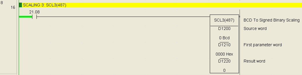
SCALING 3: SCL3(487) – Omron CP1H
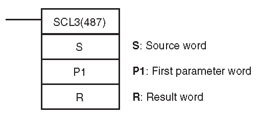
This will convert a signed BCD number into a signed binary number according to the specified linear function. An offset can be defined in the linear function.
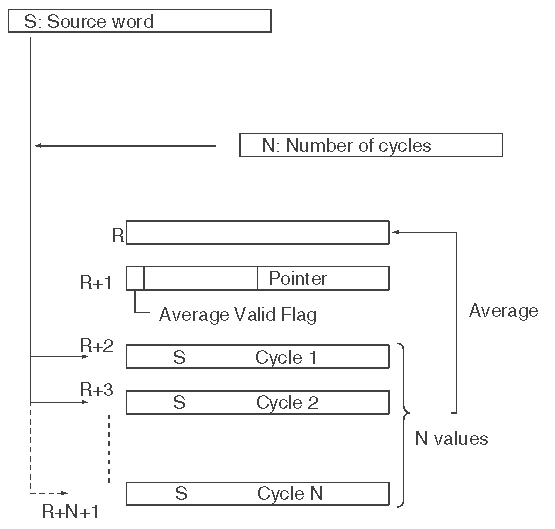
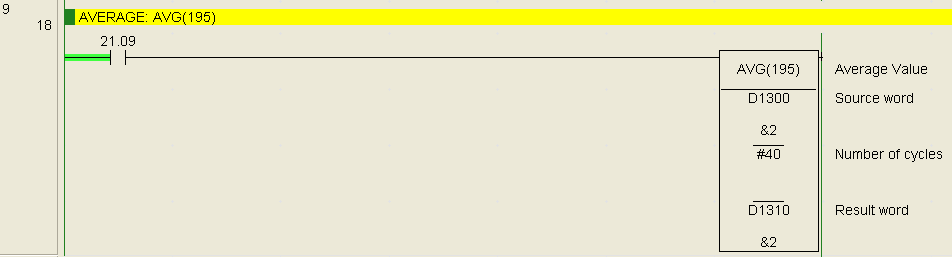
AVERAGE: AVG(195) – Omron CP1H
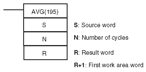
This instruction will calculate the average value of an input word for the number of cycles specified. It can help with stabilizing an analog signal.

You can see that we have many different data control instructions in the Omron CP1H. This should give you a good idea of what is possible.
See the YouTube video below on data control instructions in the Omron CP1H PLC.
The following is a list of manuals associated with the CP1H programmable logic controller. See the descriptions for each of these manuals in the first post: Omron CP1H System Hardware
W450 – SYSMAC CP Series CP1H CPU Unit Operation Manual
W451 – SYSMAC CP Series CP1H CPU Unit Programming Manual
W342 – SYSMAC CS/CJ series Communications Commands Reference Manual
W446 – SYSMAC CX-Programmer Ver. 6.1 Operation Manual
W447 – SYSMAC CX-Programmer Ver. 6.1 Operation Manual Function Blocks
W444 – CX-One FA Integrated Tool Package Setup Manual
W445 – CX-Integrator Operation Manual
W344 – CX-Protocol Operation Manual
You can download the PLC program as discussed above here.
Next time we will look at AdvancedHMI Communication to the Omron CP1H PLC.
Watch on YouTube: Omron CP1H Data Control Instructions
If you have any questions or need further information please contact me.
Thank you,
Garry
If you’re like most of my readers, you’re committed to learning about technology. Numbering systems used in PLC’s are not difficult to learn and understand. We will walk through the numbering systems used in PLCs. This includes Bits, Decimal, Hexadecimal, ASCII, and Floating Point.
To get this free article, subscribe to my free email newsletter.
Use the information to inform other people how numbering systems work. Sign up now.

The ‘Robust Data Logging for Free’ eBook is also available as a free download. The link is included when you subscribe to ACC Automation.