
We will now look at online editing, setting, and forcing that can be done on the Omron CP1H controller. The Omron CP1H series of programmable logic controllers are capable of online programming. This is when the PLC is solving logic and at the end of the scan, programming logic is added or modified. The next scan will now solve the new or modified logic in the PLC. CX-Programmer can also set or force inputs and outputs in the controller. This is usually used for troubleshooting and testing of the PLC logic. We will use the Start Stop and Jog circuit that we have developed to test the program in the PLC. Forcing and setting the inputs and outputs will demonstrate to us the operation of the logic. Online programming (online editing) will also be done with our CP1H controller.
Previously in this CP1H series, we have discussed:
System Hardware – Video
CX-Programmer – Video
Establish Communication – Video
Setting, Forcing and Online Editing – Video
Numbering System and Addressing – Video
CP1H Timers – Video
Counters – Video
Data Movement – Video
Compare Instructions – Video
Data Shift Instructions
– Video Part 1
– Video Part 2
Math Instructions – Video
Data Conversion – Video
Program Control Instructions – Video
Table Data Instructions – Video
Data Control Instructions – Video
AdvancedHMI Communication – Video
The CX-Programmer Introduction Guide provides step by step of the process of using the software. Here is the URL link for this free literature:
https://www.fa.omron.com.cn/data_pdf/mnu/r132-e1-05_cx-programmer.pdf?id=1605

A copy of this guide is a good tool to use when you learn to program using the CX-Programmer.
CX-One software has been around for a number of years. You can now get your copy from many online stores such as Ebay at a reduced cost.
Modes of the Controller – Omron CP1H Online Editing
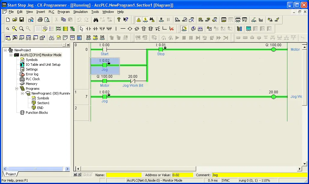
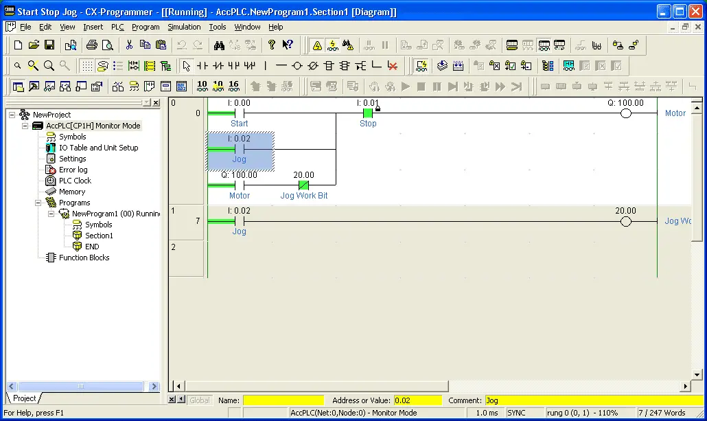
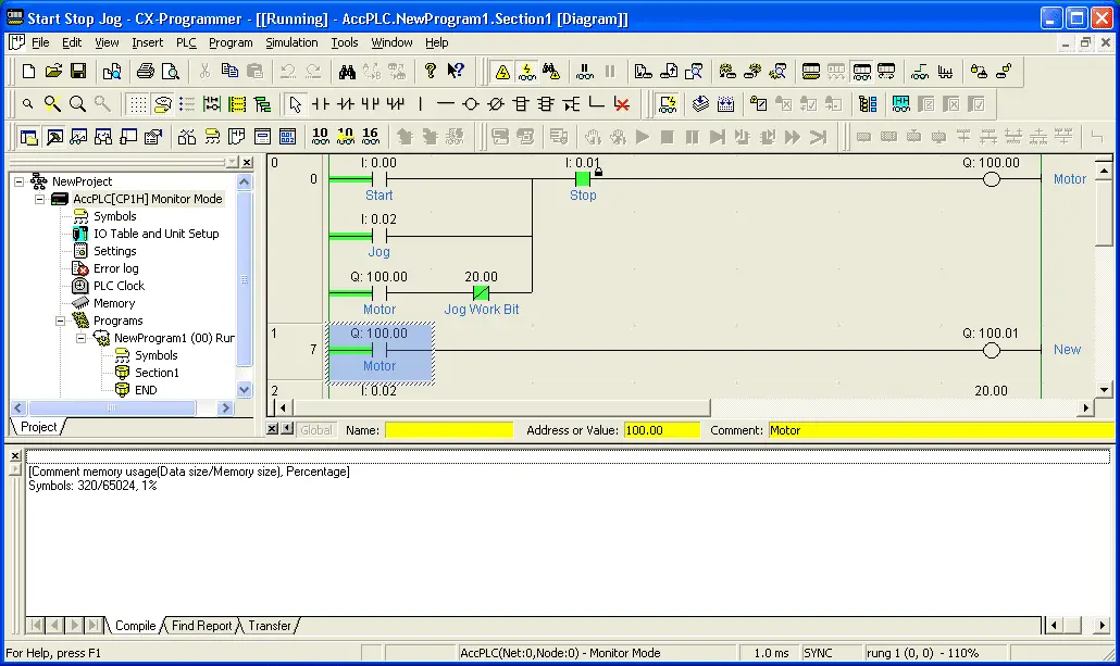
We will start by calling up our Start Stop and Jog circuit program from our previous post. Go online with the controller. Your screen should look similar to the following:
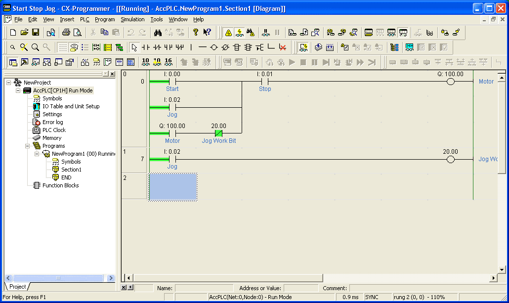
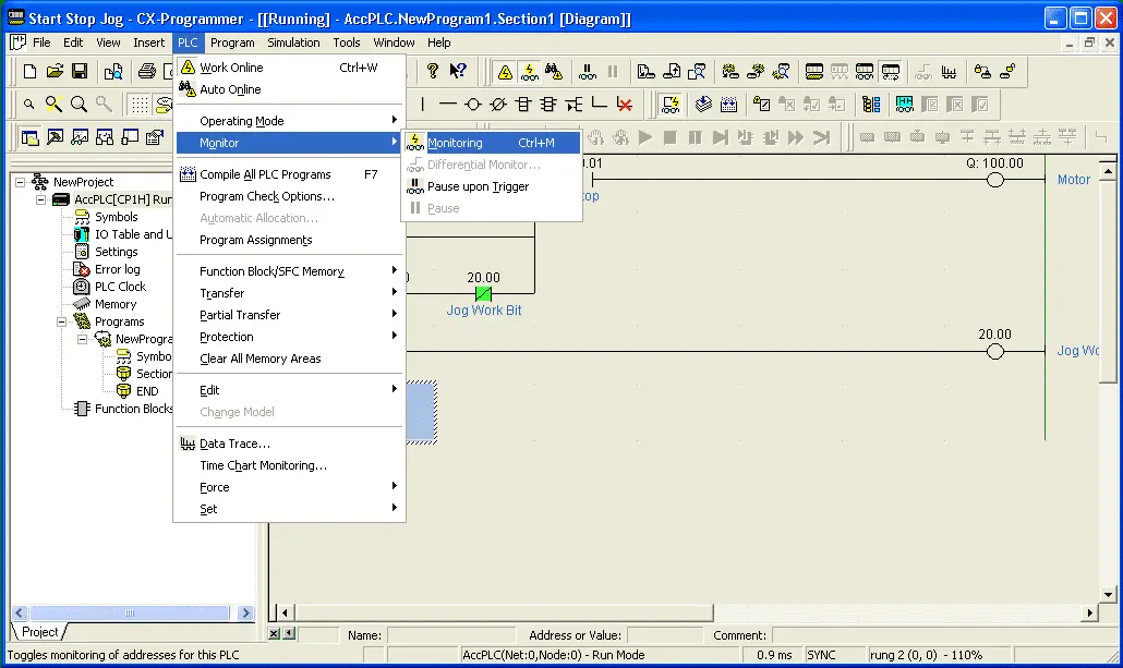
If the items are not being monitored (Green highlights on the ladder diagram) then click the monitoring icon, Ctrl + M or go to PLC | Monitor | Monitoring in the main menu.
Omron PLCs usually have three different modes; Program Monitor and Run.
Program Mode
In PROGRAM mode the CPU unit is stopped so your logic will not be executed. User programming can be created or modified, memory can be cleared, and programs can be checked. Depending on the PLC type there may be other options as well.
Monitor Mode
In MONITOR mode the CPU unit is running, so your logic will be executed. I/O is processed in the same way as in RUN mode. The operating status of the CPU unit can be monitored, bits can be forced and/or set or reset. The set values and present values of timers and counters can be modified. The present values of word data can be modified. This mode is used for system adjustments.
Run Mode
RUN mode is used for normal system operation. The operating status of the CPU unit can be monitored, but bits cannot be forced and/or set or reset. Present and set values cannot be modified using programming devices.
Let’s put our CP1H controller into monitor mode. Ctrl + 3, Monitor Icon or PLC | Operating Mode | Monitor from the main menu.

Notice that the icons on the taskbar will also allow you to change the PLC mode.

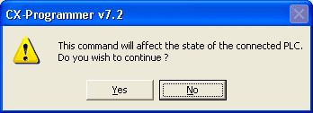
When modes are changed in the PLC, CX-Programmer will ask you if you want to proceed. Selecting YES will then change to the new mode.
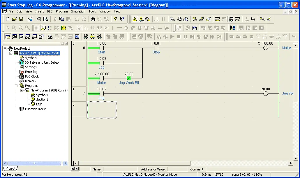
In the project tree window, the mode is always displayed next to the PLC name. AccPLC[CP1H] Monitor Mode is shown.
Forcing On, Forcing Off – Omron CP1H Online Editing
A forced contact is one that is always at that state regardless of what the actual I/O or program states. This will override any conditions on that bit and will always be Forced On or Forced Off.
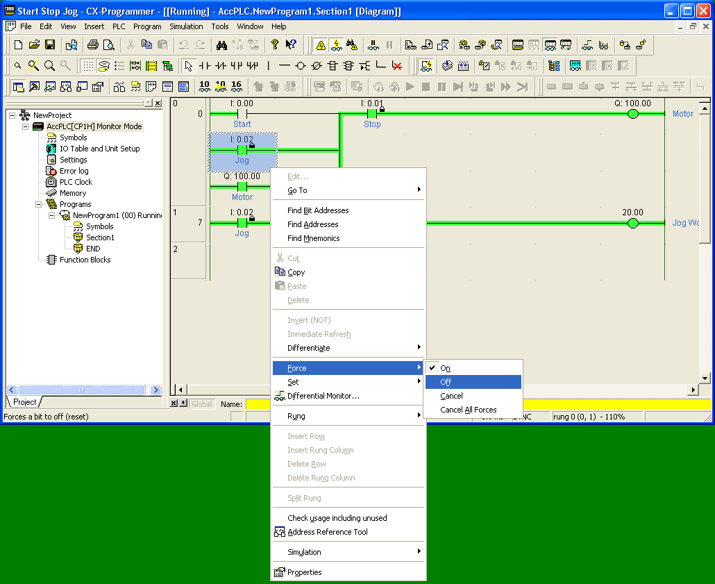
Place your cursor over the I:0.01 Stop contact. Right-click and a menu will come up. Select Force from the menu and then On.
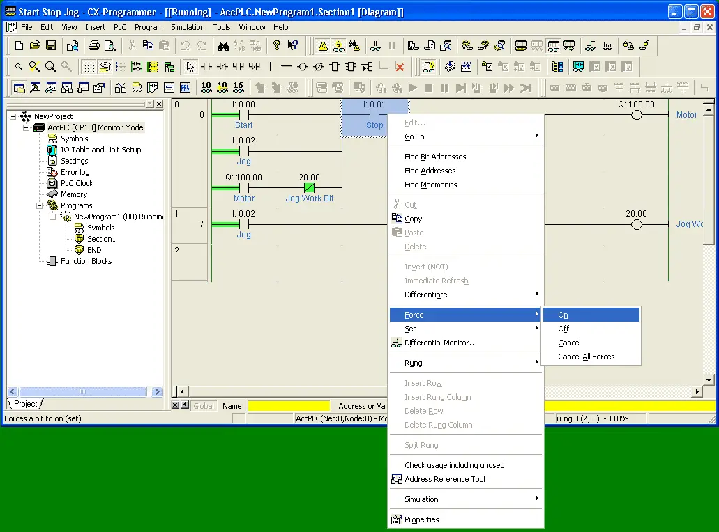
Note: I:0.01 is normally open in the logic. This stop pushbutton is usually wired up as a normally closed to the PLC. When the stop button is not touched, the input to the PLC will on or 1 because voltage is being fed through the normally closed contact.
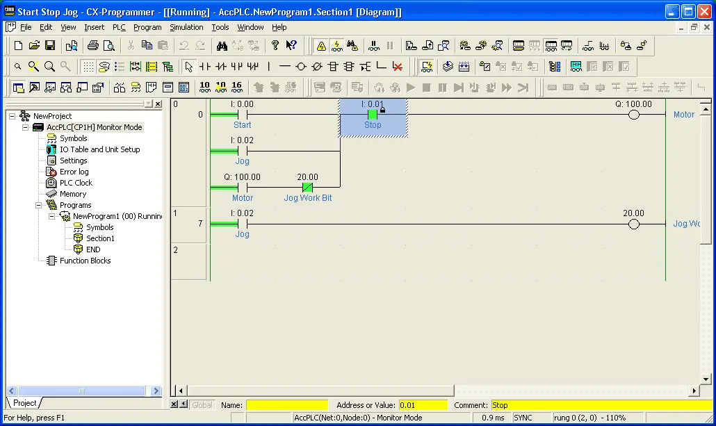
Our stop input is now forced on. This is seen by the lock symbol next to the contact on the ladder diagram. You will see that we can force contacts on, off or cancel all forces.
Setting On, Setting Off
A set contact is one that will be either turned on or off for a minimum of one scan. The CPU unit will turn the bit on/off but then at the next scan of the PLC the logic in the controller will determine the state of the bit.
Place your cursor over the I:0.00 Start contact. Right-click and a menu will come up. Select Set from the menu and then On.
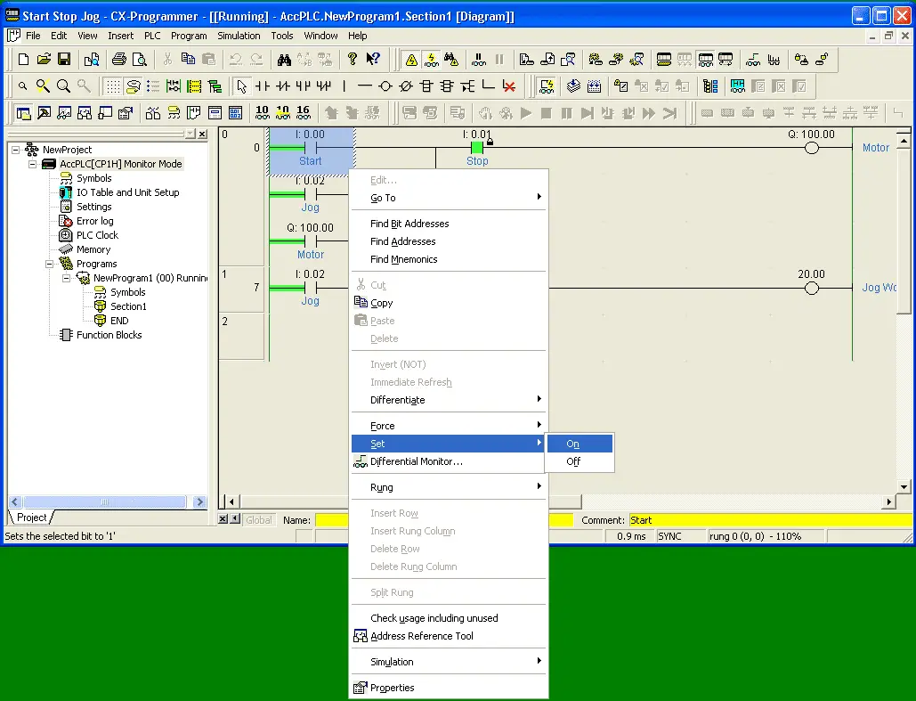
Our start bit will be on for one scan before the regular I/O scan turns the bit back off. This is too quick for us to see on our screen. Since our logic will turn on an output, we can see this on our ladder diagram. (Q:100.00 Motor)
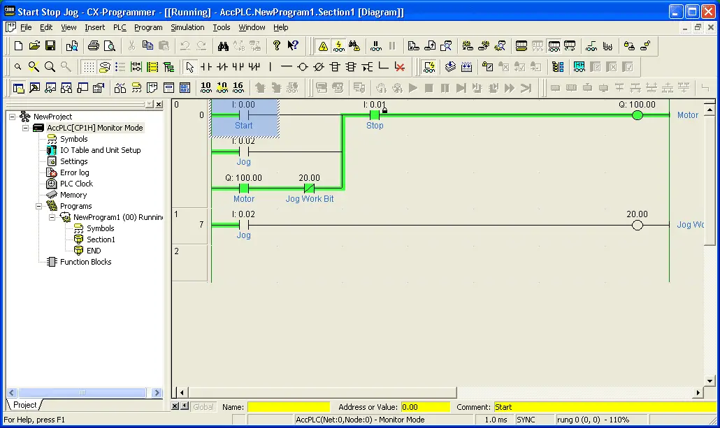
Now force on the Jog bit I:0.02. Our ladder diagram will now look like the following.
Our output will still be on until the Jog input bit I:0.02 turns off. We can turn this off by two different methods; Force Off or Force Cancel.
Look at the following result window. What did we use? Force Off or Force Cancel
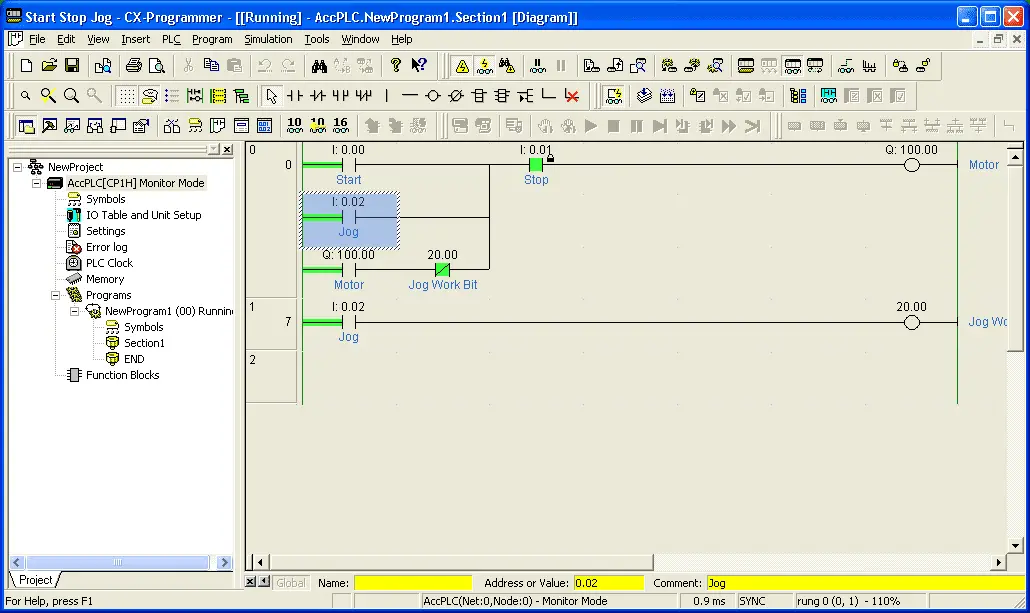
We have used the force cancel operation because the contact is not showing the force symbol next to the contact.
Online Edit – Omron CP1H Online Editing
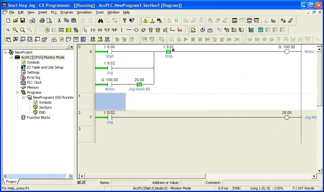
We can start online edit by hitting Ctrl + E, select the icon or from the main menu select Program | Online Edit | Begin
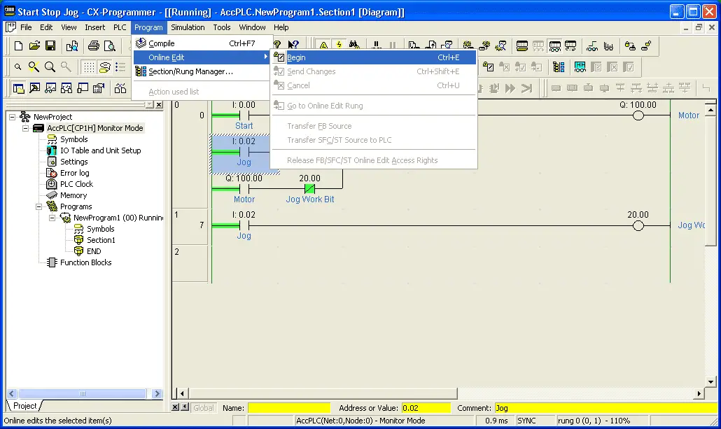
Our CP1H is still running the logic. (Monitor Mode) The current rung background that is being modified is white.
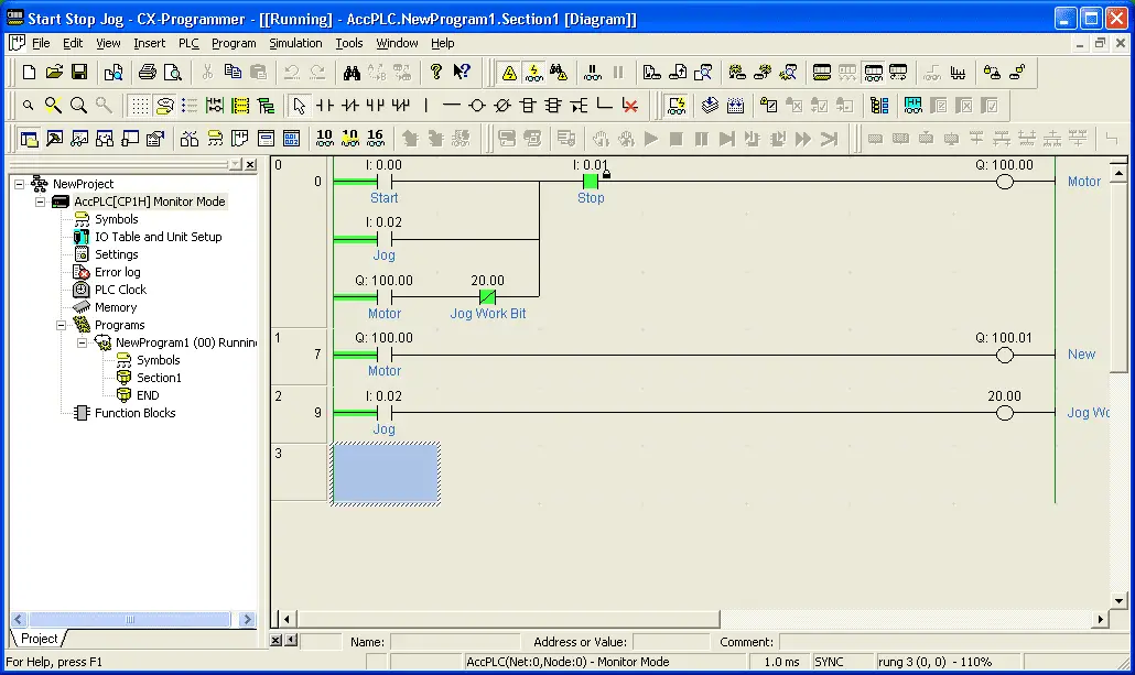
We will now insert a new rung below. Select Insert | Rung | Below from the main menu. This will now allow us to input our new rung logic.
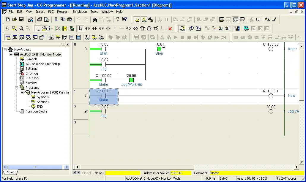
We will use our Motor output Q:100.00 to turn on a new output Q:100.01. Use the same methods as we did when we discussed the CX-Programmer. You will notice that the left side of the run will be red until the rung is complete.
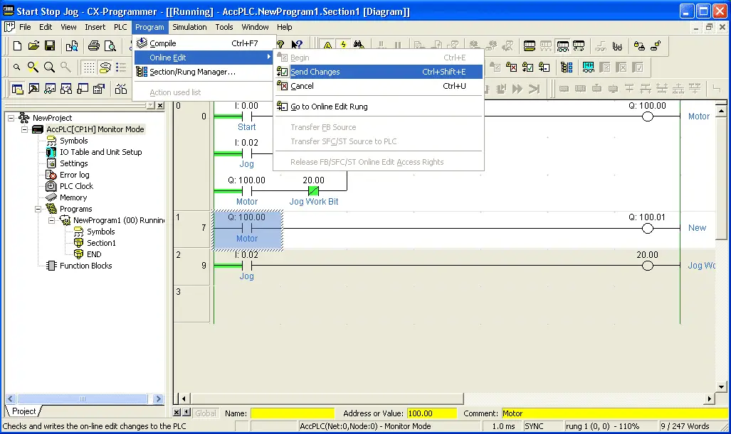
In order to save the changes, you can press Ctrl + Shift + E, Select the Icon, or select Program | Online Edit | Send Changes from the main menu.
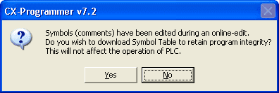
You will get a warning message when we modify the symbol table during the online edit. Select Yes.
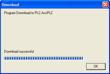
The program will then be downloaded into the controller. A message window will be displayed when the download is successful. Select OK.
We now have our new rung into the controller and running.
Our output window is displayed showing our memory usage. We can close this window by hitting the ‘X’ in the left top corner.
Forcing, setting, and online editing are useful tools to troubleshoot and monitor your logic in the PLC. Like any new software you will become efficient in doing this with practice.
See the logic in the CP1H PLC by watching the YouTube video below. There is also a quick way to monitor the words and bits in the rung using the watch window.
The following is a list of manuals associated with the CP1H programmable logic controller. See the descriptions for each of these manuals in the first post: Omron CP1H System Hardware
W450 – SYSMAC CP Series CP1H CPU Unit Operation Manual
W451 – SYSMAC CP Series CP1H CPU Unit Programming Manual
W342 – SYSMAC CS/CJseries Communications Commands Reference Manual
W446 – SYSMAC CX-Programmer Ver. 6.1 Operation Manual
W447 – SYSMAC CX-Programmer Ver. 6.1 Operation Manual Function Blocks
W444 – CX-One FA Integrated Tool Package Setup Manual
W445 – CX-Integrator Operation Manual
W344 – CX-Protocol Operation Manual
You can download the PLC program as discussed above here.
Next time we will look at numbering systems and addressing with the CP1H PLC.
Watch on YouTube: Omron CP1H Setting, Forcing and Online Editing
If you have any questions or need further information please contact me.
Thank you,
Garry
If you’re like most of my readers, you’re committed to learning about technology. Numbering systems used in PLC’s are not difficult to learn and understand. We will walk through the numbering systems used in PLCs. This includes Bits, Decimal, Hexadecimal, ASCII and Floating Point.
To get this free article, subscribe to my free email newsletter.
Use the information to inform other people how numbering systems work. Sign up now.

The ‘Robust Data Logging for Free’ eBook is also available as a free download. The link is included when you subscribe to ACC Automation.