People often ask “What is a PLC?” and “PLC Meaning”. A programmable logic controller (PLC) is a piece of hardware that isolates inputs from outputs. Programs are written to look at the inputs solve logic and set the outputs to perform work. Today we are going to look at the basic fundamental way we program. Every PLC company will do this…
Bits in PLC Memory
Everything in the programmable logic controller actually boils down to bits in the memory.
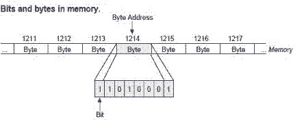
It is these bits that we manipulate in order to accomplish the work that we need to be done by the PLC. The instruction set is the method we use to do this. In general, there are several ways to view the bits. Discrete input and output, Numbers and Position of bits will be covered. Understanding the different ways in which we can view these bits will help in developing programs.
Bits are part of the memory of all PLC systems. The memory can be retentive or non-memory retentive. Memory retentive means that if power is lost to the PLC, the status of the bit remains the same when power is restored. If the bit is non-memory retentive, and power is lost the bit returns to the off state. Addressing refers to how the controller understands what memory location to look at. When we address memory in the PLC we can do this in two different ways:
Direct Addressing: Specify a location of the memory location
Indirect Addressing: Specify a location that contains a value to point to the memory location required.
Refer to the manual of the specific PLC that you are using for the way in which memory is addressed and if it is memory retentive or not.
Discrete On/Off Bits in the PLC
Discrete bits are the basic building blocks in the PLC. When we talk of digital I/O this is referring to the individual bits that you can wire switches, pushbuttons, proximity sensors, or any other device that is either on or off. (1 or 0) They can be usually wired to the PLC as a normally open or normally closed contact. The ladder logic is written in a way that you examine the bit as either on or off.
HOW PLC INPUTS WORK
Bit Frequency in the PLC
We also must look at the frequency (rate of change from off to on) of the input bits or output in some cases. The maximum frequency that we can read an input to the PLC will be determined by the scan of the PLC.
Example:
A 2 ms Scan (0.002 seconds) means that we can read the inputs and solve the logic in 2 ms. In order to ensure that the input is read in both states (on / off) we have to ensure that the input is off or on for at least 2 ms. The maximum frequency (Switching / Second) that the input could switch would be 2 ms = 1/.002 times per second = 500hz
Numbers using Bits in the PLC
Numbers in the PLC are all based on binary. Analog inputs and outputs are based upon the number of bits put together in order to display the range for the input. (12 bit or 16 bit) The values from the analog 12bit input will go from 000 to FFF base 16 (Hex). Hexadecimal is used to display the binary bits in the word or register. Some of the more common numbering systems in the PLC are binary, hexadecimal, BCD (binary coded decimal) and octal (based on 8 bits)
![]()
Additional Information on understanding numbering systems in the PLC:
What Everybody Ought to Know about PLC (Programmable Logic Controller) Numbering Systems
Bit Position in the PLC
Position of the bits within the word, stack, or accumulator can be very useful. Usually, we can use this to track items. A typical example of this is to track items on a conveyor belt. The belt movement is usually a pulse input from an encoder. A sensor indicates the item on the conveyor.
PLC PROGRAMMING EXAMPLE – SHIFT REGISTER (CONVEYOR REJECT)
Bits are the basic building blocks that we use to program programmable logic controllers. The three ways to view bits (Discrete, Number, and Position) will help users to understand the different ways to program.
Here are some additional links that you may find helpful:
Five Steps to PLC Program Development
PLC Programming Example – Process Mixer
PLC Programming Example – Shift Register (Conveyor Reject)
PLC Programming Example – Paint Spraying
The Secret of Using Counters
The Secret of Using Timers
Watch on YouTube: PLC Bits Numbers and Position
If you have any questions or need further information please contact me.
Thank you,
Garry
If you’re like most of my readers, you’re committed to learning about technology. Numbering systems used in PLCs are not difficult to learn and understand. We will walk through the numbering systems used in PLCs. This includes Bits, Decimal, Hexadecimal, ASCII, and Floating Point.
To get this free article, subscribe to my free email newsletter.
Use the information to inform other people how numbering systems work. Sign up now.

The ‘Robust Data Logging for Free’ eBook is also available as a free download. The link is included when you subscribe to ACC Automation.