The Productivity Suite Software allows us to modify our existing program and execute the new code without stopping the scanning of the PLC. This is referred to as online editing. We change the ladder logic code and when we save it to the PLC, the current scan of the PLC is held until the new code is written into the unit. It then releases the scan and our new program starts to execute. This happens in milliseconds so our process can continue to operate.
Troubleshooting the logic in our PLC sometimes can be difficult. The Productivity Suite Software has a Debug Mode. This will allow us to control the scan cycle of the PLC, decide on the rungs to execute, and control the physical outputs during this time. This ability of control helps to fix errors or understand existing code in our programmable logic controller.
We will be taking our existing Start / Stop circuit from last time and add a Jog input using online editing. We will then use the debug mode in the Productivity Suite software to understand the scan and the jog function that we added.
Let’s get started.
Previously in this Productivity 1000 series PLC, we have discussed:
System Hardware – Video
Installing the Software – Video
Establishing Communication – Video
First Program – Video
Documenting the Program – Video
Monitoring and Testing the Program – Video
Online Editing – Productivity
We will be modifying our Start Stop Circuit program that we made previously.
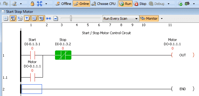
Currently, we are online and in run mode with our Productivity controller. The ladder is being monitored because you can see the highlighted logic.
We will first change the first rung comment. You can double click the rung comment or right click on the rung and select edit rung comment.
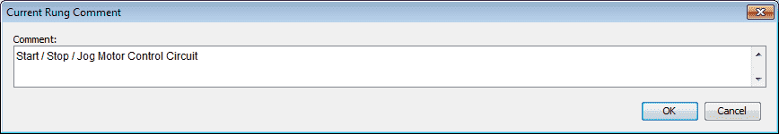
Modify the Current Rung Comment to Start / Stop / Jog Motor Control Circuit. Click OK
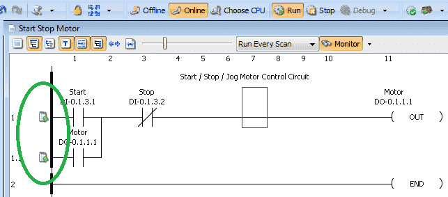
You will notice that the IO in the rung are not being monitored and highlighted anymore. This is because we have changed the rung. The symbols on the left side of the rung indicate that we have not saved or transferred our program to the CPU.
Let’s now add our Jog rung.
Out jog contact will be DI.0.1.3.3 this is the next address on our physical IO. The Out Coil (OUT) will be an internal bit called Jog_Work_Bit. This can be any name that you want to call the bit.
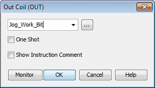
We will just enter the name and hit OK.
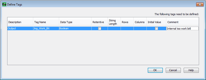
A define tags window will now appear. This is because our internal bit is currently not in the tag database. We will leave the default values and we can add a comment. Select OK to place our bit in the database.

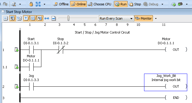
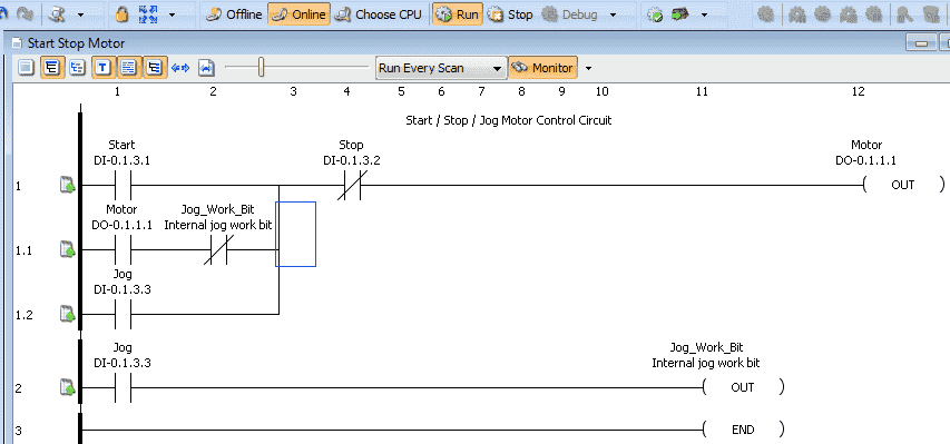
Our program now looks like this with our Jog rung.
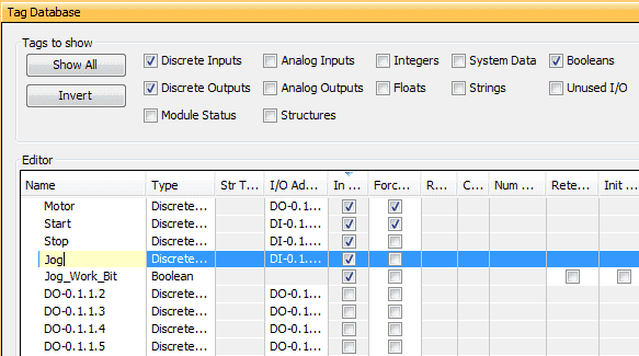
Call up our tag database so we can change the name of our input to Jog. This is done through the main menu | Edit | Tag Database or select Tag Database under the Write a program in the application tools menu.
Note: We could have started with entering our new tags in the Tag Database before we started to program.
Click the X in the upper right corner of the Tag Database to close the window.
We will now add the Jog functionality to our first rung.
Note: To add the Jog_Work_Bit next to the Motor you must insert a column.
We can now save the program to file by using the save icon or select File | Save Project from the main menu.
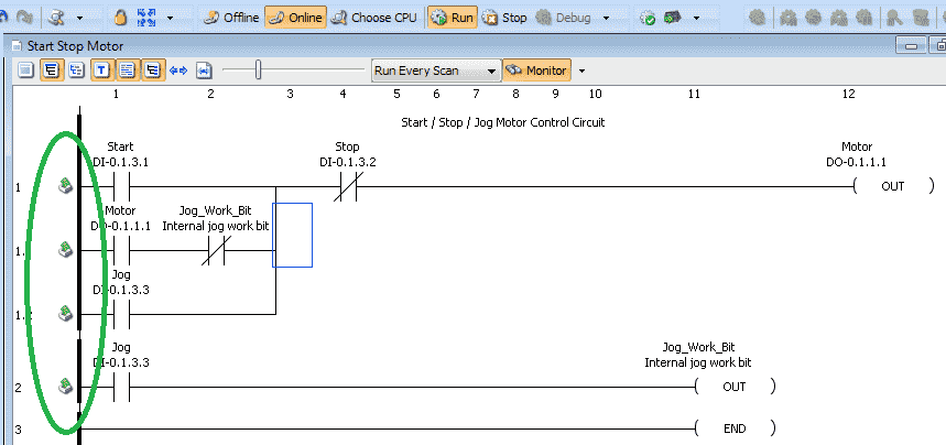
The symbols on the left of the rungs have now changed to indicate that the project is saved but not transferred to the CPU.
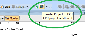
Select the Transfer Project to CPU icon or select File | Transfer Project | To CPU…
You can also use the keyboard shortcut of Shift + F9.
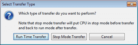
A select transfer type window will now be displayed. We will select the Run Time Transfer option. This will continue to run our program while the new program is being put into the PLC.
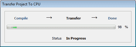
The transfer project to the CPU window will show the status of the transfer.
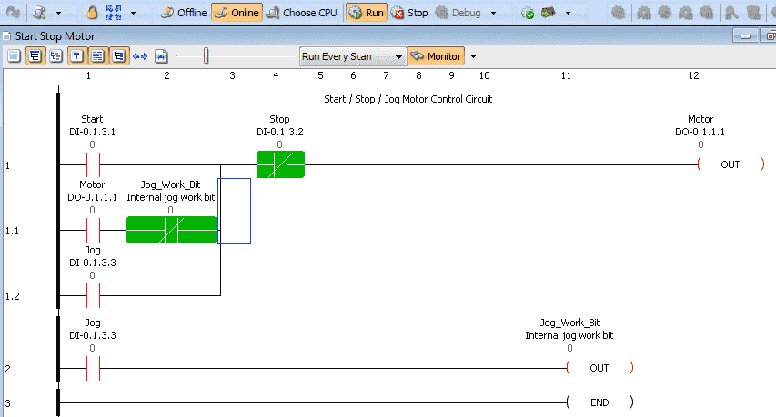
When the online transfer is complete to the Productivity controller, the rungs will now be monitored as usual. Our new program is now being run in our PLC.
Here is a post that will explain the logic behind our new Stop-Start Jog program circuit.
https://accautomation.ca/how-to-make-a-start-stop-jog-circuit-in-a-plc/
Debug Mode – Productivity Online Editing (Troubleshooting)
To enable debug mode the Productivity CPU must be online and the CPU mode switch must be in the run position. Stop mode must be activated through the Productivity Suite software.

Select the stop icon on the main menu or select CPU | Stop from the main menu.
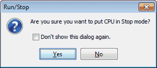
Select Yes to put the CPU in stop mode.

We can now select the debug mode of the productivity suite software.
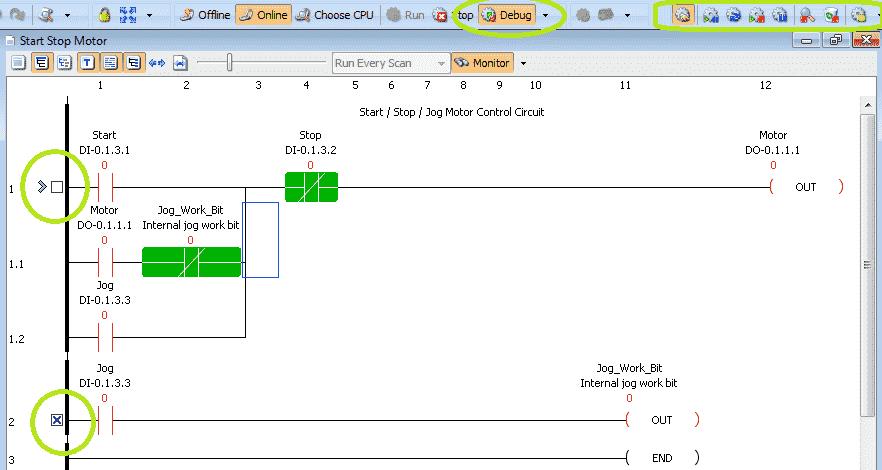
There are three ways of calling debug mode. Use the Debug Icon located on the main screen. Select the Debug menu item from the CPU menu located on the main menu or select the Debug item from the application tools panel.

When in debug mode a box is placed beside each rung in our program.

The arrow will be pointing to the current rung. We can set up breakpoints in our logic by clicking the box.

This will place an ‘X’ in the box representing a breakpoint.
When in debug mode a series of icons will help us control the execution of our logic, so we can troubleshoot.

Here are the descriptions of each of the icons in debug mode.


This menu runs similar to your music player. You can pause, run one scan, step through your program.
The debug tool is invaluable when troubleshooting your logic. See this in action in the video below.
Download our program here.
Watch the video below to see how we can online edit and debug our program in our Productivity 1000 Series PLC.
Productivity 1000 Series PLC from Automation Direct
Overview Link (Additional Information on the Unit)
Configuration (Configure and purchase a system – BOM)
User Manual and Inserts (Installation and Setup Guides)
Productivity Suite Programming Software (Free Download Link)
This software contains all of the instruction sets and help files for the Productivity Series.
Next time we will look more at the tag database and numbering systems in the Productivity 1000 Series PLC.
Watch on YouTube: Productivity 1000 Series PLC – Online Editing and Debug Mode
If you have any questions or need further information please contact me.
Thank you,
Garry
If you’re like most of my readers, you’re committed to learning about technology. Numbering systems used in PLC’s are not difficult to learn and understand. We will walk through the numbering systems used in PLCs. This includes Bits, Decimal, Hexadecimal, ASCII and Floating Point.
To get this free article, subscribe to my free email newsletter.
Use the information to inform other people how numbering systems work. Sign up now.

The ‘Robust Data Logging for Free’ eBook is also available as a free download. The link is included when you subscribe to ACC Automation.