Modbus RTU will be the serial (RS485) method in which we will communicate between the AdvancedHMI Screen and the Automation Direct Solo Process Temperature Controller.
We can address up to 247 (Solo 1 to 247) devices on this master-slave protocol. A maximum of 32 devices (Nodes) on the network can communicate to the master. A review of the Modbus RTU protocol can be seen at the following URL.
http://www.rtautomation.com/technologies/modbus-rtu/
AdvancedHMI is a free HMI programming package the runs on Microsoft Visual Studio. It can be downloaded at the following URL.
https://sourceforge.net/projects/advancedhmi/
Connections – AdvancedHMI to Solo Process Temperature Controller
We will be running the AdvancedHMI software on the computer. One of the USB ports will have a USB to RS485 adapter and communicate RS485 to the Solo process temperature controller.
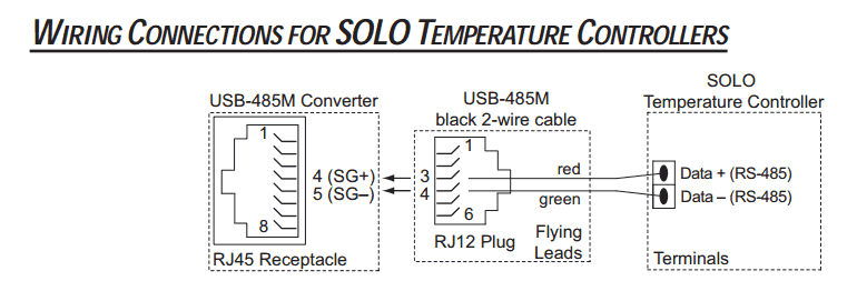
See the following post to install the USB to RS485 adapter.
https://accautomation.ca/usb-to-rs485-pc-adapter-installation/
Solo Controller Settings
In the Initial Setting Mode we will change the online configuration and make the changes to the Modbus settings as follows: 9600 Baud, Even, 7 Data Bits, 1 Stop Bit, Modbus ASCII Format. We will leave the default unit number as 1. See the following post to set the controller:
https://accautomation.ca/solo-process-temperature-controller/
Modbus RTU (Addresses)
The following address will be used in our project:
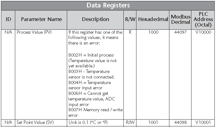
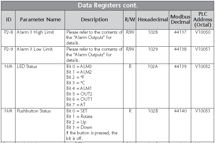
AdvancedHMI will use the Modbus Decimal value in the PLCAddressValue to determine the information that you want to get. For a list of all Modbus addresses that can be used in your project, refer to the Solo Manual located a the following URL:
https://www.automationdirect.com/adc/Manuals/Catalog/Process_Control_-a-_Measurement/Temperature_-z-_Process_Controllers
Screen Display: (AdvancedHMI)
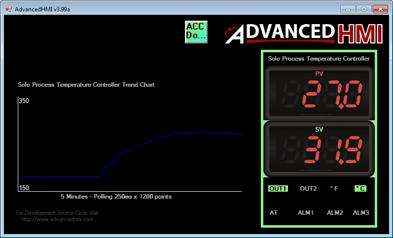
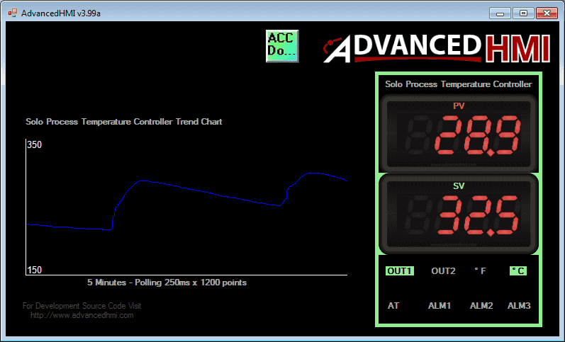
Here is what our screen will look like:
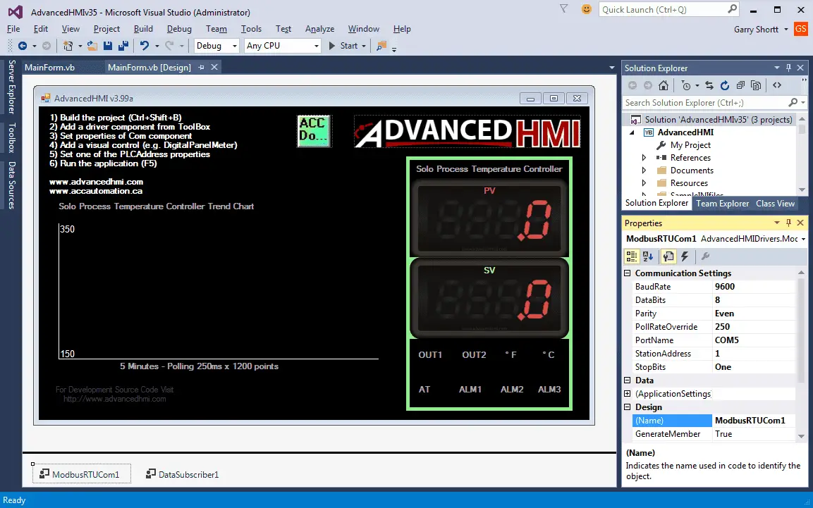
We have mimicked the look of the solo process temperature controller. Our PV and SV values are DigitalPanelMeters from the AdvancedHMI toolbar. The eight output indicators are just labels.
Our ModbusRTUCom1 settings are as follows:
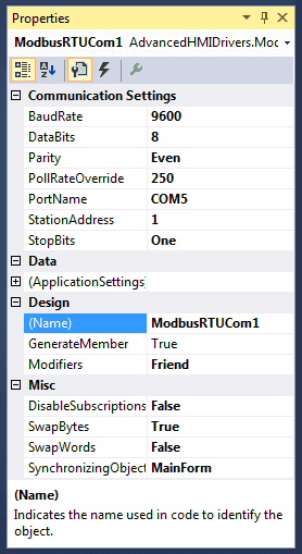
Settings: 9600, 8, Even, One StopBit and Station 1 should all match the settings in the Solo process temperature controller that we did previously.
PollRateOverride will allow us to determine how often communication will take place to the controller. (250msec)
The PortName will be the same port number that the computer will communicate out of. This will be set when you install the USB to RS485 adapter. It may change if a different USB port is used.
The DataSubsciber1 will be used to determine the status of the controller.
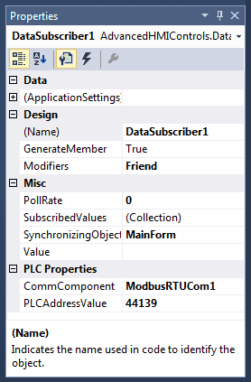
PLCAddressValue = 44139
We read the value of the eight status bits and convert this into a string so we can determine the status of each of the individual bits. Here is the code that is used to do this. It is the only code required for this application.
Private Sub DataSubscriber1_DataChanged(sender As Object, e AsDrivers.Common.PlcComEventArgs) Handles DataSubscriber1.DataChanged
        Dim i As Integer = DataSubscriber1.Value
        Dim Status As String
        Status = Convert.ToString(i, 2).PadLeft(8, "0") '8 bits
        'There are 8 bits that we need to check and account for on our screen.
        'Modbus Decimal - 44139
        'Bit 0 - ALM3 - Alarm 3
        'Bit 1 - ALM2 - Alarm 2
        'Bit 2 - C degrees
        'Bit 3 - F degrees
        'Bit 4 - ALM1 - Alarm 1
        'Bit 5 - OUT 2
        'Bit 6 - OUT 1
        'Bit 7 - AT - Auto Tuning
The complete AdvancedHMI code for this application can be downloaded at the end of the post.
The PV and SV indicators are DigitalPanelMeters as mentioned above.
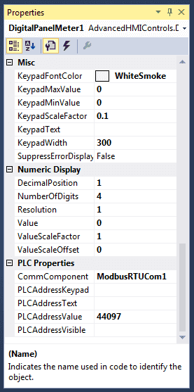
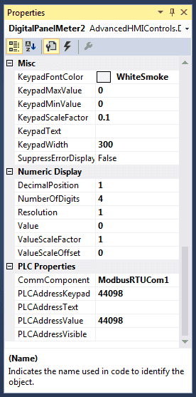
They both have four digits with a decimal position of 1. This will give us a value between 000.0 and 999.9.
The SV includes a keypad to change the set value. KeypadScaleFactor is set to 0.1 to allow for the decimal place.
Included in our display is a BasicTrendChart from the AdvancedHMI toolbar.
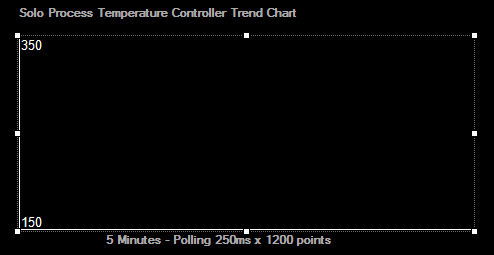
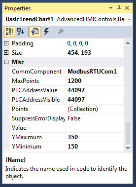
You want to make sure that the YMaximum and YMinimum settings are set to the values will not go past these settings. If they do then the graph line will disappear from the chart at that point and time.
This will show a running trend for the last 5 minutes.
Polling rate is 250msec x 1200 points in the chart = 300 000msec
300 000msec / 1000 = 300 seconds
300 seconds / 60 (seconds in minute) = 5 minutes
Notes: Displaying Extended ASCII Symbols in Visual Studio (VB.NET)
You can display any symbol in the visual studio environment by holding the ‘Alt’ key down and typing the decimal number of the symbol that you want. In our example, the degrees symbol is Alt 248.
Here are the extended ASCII symbols:
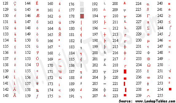
http://www.asciitable.com/
You will notice that the response rate is very quick. (250msec) As the PV, SV or indication values change, the screen will get updated.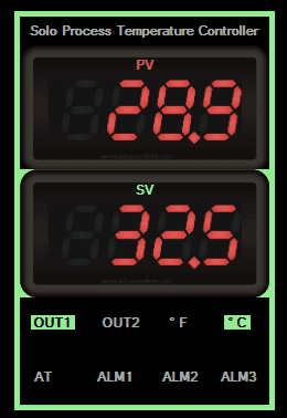
The trend chart will show the last 5 minutes of the PV value. 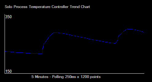
As you can see, programming the AdvancedHMI to communicate to the Solo process temperature controller is very easily done.
Download the AdvancedHMI code for this project here.
Watch on YouTube: AdvancedHMI to Solo Process Temperature Controller
If you have any questions or need further information please contact me.
Thank you,
Garry
If you’re like most of my readers, you’re committed to learning about technology. Numbering systems used in PLCs are not difficult to learn and understand. We will walk through the numbering systems used in PLCs. This includes Bits, Decimal, Hexadecimal, ASCII, and Floating Point.
To get this free article, subscribe to my free email newsletter.
Use the information to inform other people how numbering systems work. Sign up now.
The ‘Robust Data Logging for Free’ eBook is also available as a free download. The link is included when you subscribe to ACC Automation.

