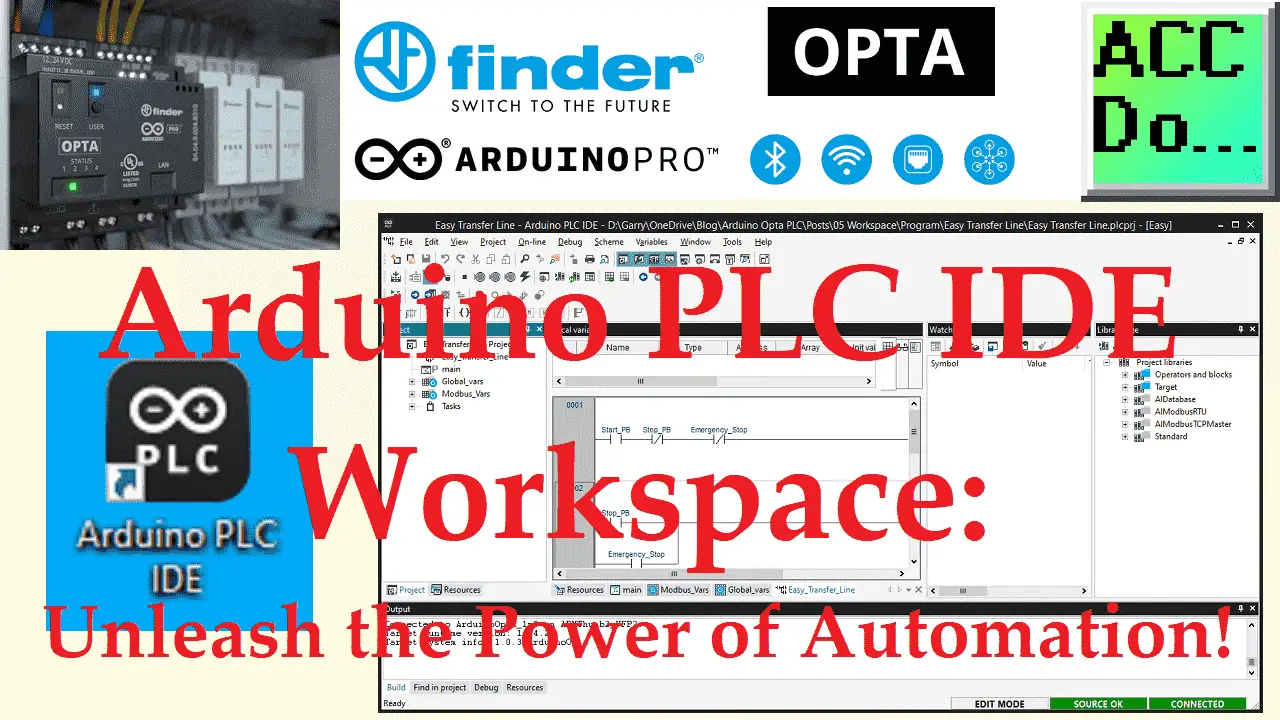
The Arduino PLC IDE is an Integrated Development Environment that supports all languages defined in the IEC standard. This software’s workspace facilitates all the activities involved in creating an application, including textual source code editors for Instruction List (IL) and Structured Text (ST) programming languages, as well as graphical source code editors for Ladder Diagram (LD), Function Block Diagram (FBD), and Sequential Function Chart (SFC) programming languages.
Additionally, the IDE includes a compiler that translates IEC-standard applications directly into machine code, eliminating the need for a runtime interpreter and ensuring fast program execution.
The communication system allows for the application to be downloaded to the target environment, such as the OPTA PLC, and the IDE also provides an array of debugging tools, ranging from an easy-to-use watch window to more advanced sampling tools that gather accurate and reliable data directly from the target environment.
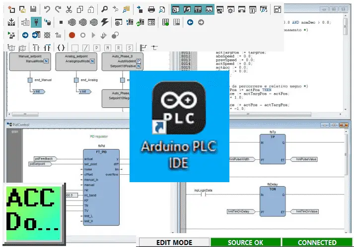
This post examines the Arduino PLC IDE Workspace and its different components. We’ll briefly discuss each element so that you can grasp its functions and how it can aid in your automation solution. Let’s get started.
The entire Arduino Opta IoT PLC Series is located here.
Previously in this series, we have discussed the following:
Opta Introduction Video
Arduino Opta IoT PLC Cutting Edge Hardware – Video
Arduino Opta Software Installation – Video
Arduino Opta IoT PLC Quick Start Ladder Logic – Video
Easy Steps to Establish Communication between Arduino Opta IoT PLC – Video
Note: A post is usually associated with each video. This will provide additional details and links discussed.
Workspace
Watch the video below to see the elements of the Arduino PLC IDE software workspace. You will also see how these items can be customized to your preference.
Workspace Window
You’ll notice two separate panels within the Workspace window: the project and resources panels.
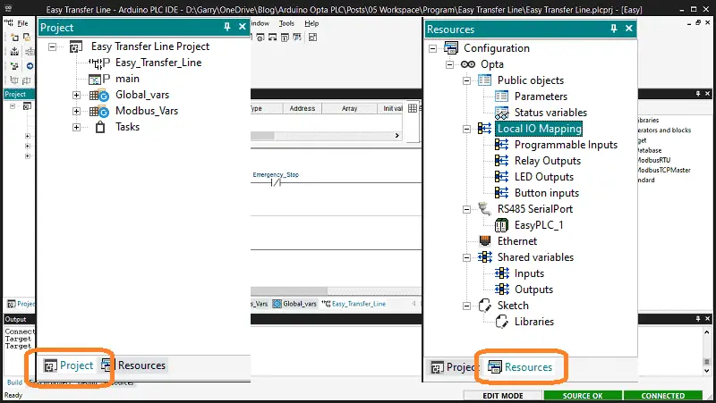
The Project panel is where you’ll find all the elements of your project organized in a tree-like structure. You can add custom folders to the project tree to reorganize the details according to your preferences. In this panel, you’ll also find the task list, which displays available tasks and the programs that have been assigned to them. The contents of the Resources panel vary depending on how the target device is interfacing with the PLC IDE. It may include configuration elements, schemes, wizards, and more.
Output Window
In the PLC IDE, all output messages are printed in the Output window.
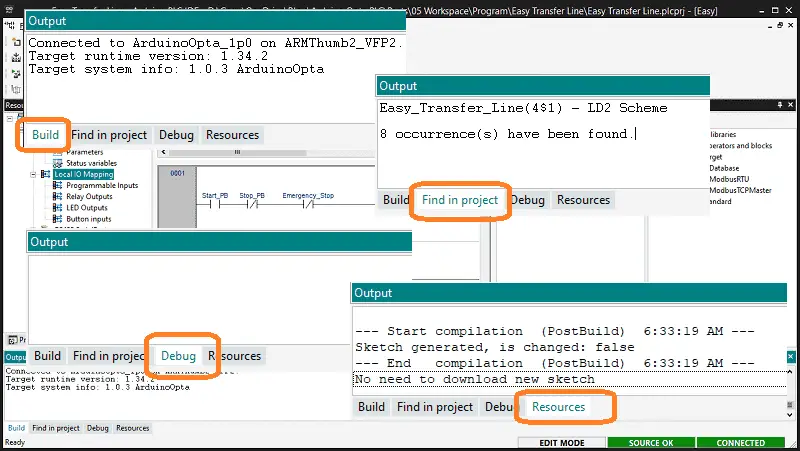
It consists of four tabs: Build, Find in Project, Debug, and Resources. The Build tab displays the output when a project is opened, compiled, or code is downloaded to the target device. The “Find in Project” tab shows the result of the Find in Project activity. The Debug tab provides information about advanced debugging activities such as breakpoints. Additionally, depending on the target device being interfaced with, the PLC IDE can print every PLC runtime error on this output window, pinpointing the exact location of the error. Lastly, the Resources tab displays messages related to the specific target device the PLC IDE is interfacing with.
Source Code Editors
The programming environment of the PLC IDE comes equipped with a range of editors, which enable users to handle, modify, and print source files in any of the five programming languages outlined by the IEC 61131-3 standard.
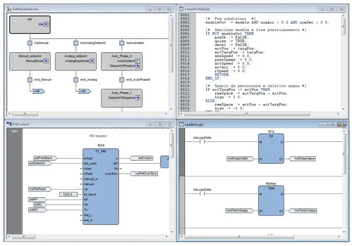
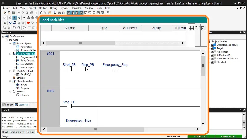
Additionally, there are spreadsheet-like editors that facilitate the creation of both global and local variables.
Watch the video below to see this element.
Document Bar
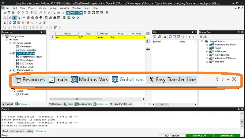
In the PLC IDE, the Document bar displays a list of currently open documents available for editing.
Watch Window
The Watch window is a useful debugging tool, among many others.
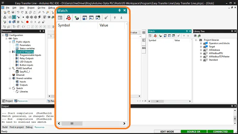
The oscilloscope, triggers, and live debug mode are noteworthy debugging tools.
Library Tree
Libraries are a powerful tool for sharing objects between PLC IDE projects.
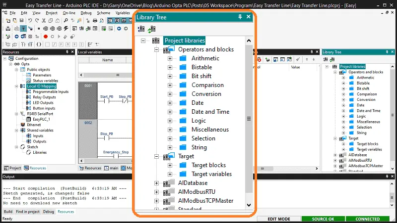
Inside the library tree are elements like Operators and Standard Blocks, which list language elements, such as operators and functions defined by the IEC 61131-3 standard.
System variables (Target variables) list all the variables between the firmware and PLC application code.
Target definitions list all the system functions and function blocks available on the specific target device.
Status Bar
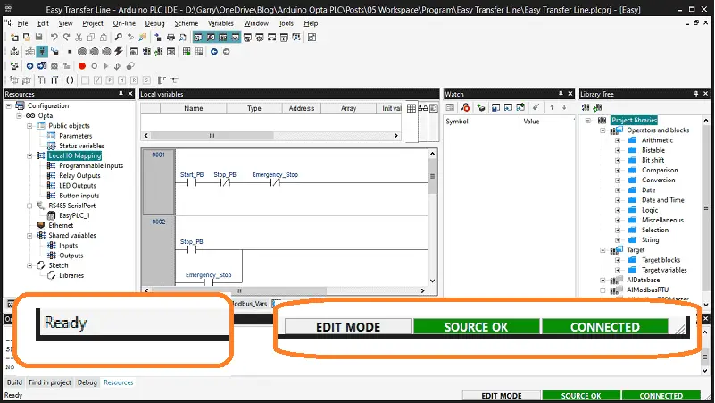
The Status bar displays the application’s state on its left side, and an animated control reports the communication state on its right side.
Toolbars
Arduino PLC IDE software allows you to hide or show specific toolbars to customize the workspace fully.
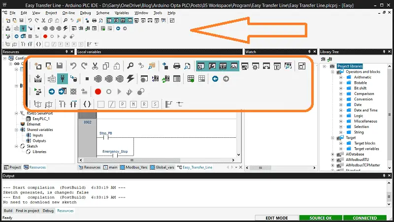
The toolbars contain icons that work as shortcuts for the menu commands.
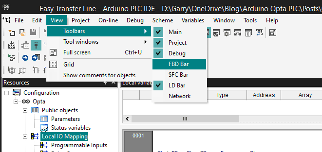
Each method of programming in the environment will have a toolbar. Other toolbars are there to perform functions like downloading, compiling, adding variables, etc.
Watch the video below to see these elements of the Arduino PLC IDE software workspace.
Arduino Opta PLC – IoT and Industry 4.0 Enabler
Arduino Opto IoT PLC Series
Opta – Frequently Asked Questions (FAQ)
Finder OPTA 8A Series – Tutorials
Datasheet
Quickstart Sheet
Arduino Opta Hardware
Arduino PLC IDE
Arduino Software Download Page
(Arduino IDE, PLC IDE, PLC IDE Tools)
Watch on YouTube: Arduino PLC IDE Workspace: Unleash the Power of Automation!
If you have any questions or need further information, please contact me.
Thank you,
Garry
If you’re like most of my readers, you’re committed to learning about technology. Numbering systems used in PLCs are not challenging to learn and understand. We will walk through the numbering systems used in PLCs. This includes Bits, decimals, Hexadecimal, ASCII, and Floating points.
To get this free article, subscribe to my free email newsletter.
Use the information to inform other people how numbering systems work. Sign up now.
The ‘Robust Data Logging for Free’ eBook is also available for free download. The link is included when you subscribe to ACC Automation.

