In this tutorial, you will learn how to program a chain conveyor transfer using Do-More. The EasyPLC software suite includes a Machine Simulator (MS) with pre-programmed machines, including the chain conveyor. This machine can move boxes of various sizes along the production line, transferring them to different locations.
We will use the Do-More Designer PLC software to program this virtual machine and connect the simulator to the chain conveyor. Communication will be established through Modbus TCP (Ethernet). We will follow the five steps of program development to guide you through the process. Let’s get started!
Learn PLC programming the easy way. See below for a 10% discount on this cost-effective learning tool. Invest in yourself today.
The entire series can be found here.
Here are some previous posts we have done:
Easy PLC Installing the Software – Video
EasyPLC Software Suite – Quick Start – Video
Click PLC – Easy Transfer Line Programming – Video
Productivity PLC Simulator – Chain Conveyor MS – Video
Do-More PLC – EasyPLC Box Selection Program – Video
Click PLC EasyPLC Gantry Simulator – Video
Click PLC Simple Conveyor EasyPLC – Video
EasyPLC Paint Line Bit Shift – BRX Do-More PLC – Video
Click PLC – EasyPLC PLC Mixer Programming – Video
Click PLC EasyPLC Warehouse Stacker Example – Video
– Operation Video
EasyPLC Machine Simulator Productivity PLC Robotic Cell – Video
EasyPLC Simulator Robotic Cell Click PLC – Video
EasyPLC Simulator Robotic Cell BRX Do-More PLC – Video
– EasyPLC Factory Editor Robotic Cell Additions Video
4 Way Traffic Light PLC Program EasyPLC – Video
Rock Crusher Plant EasyPLC BRX Do-More – Video
Freight Carrier Weighing and Distribution EasyPLC – Video
EasyPLC Machining Center Loading Robots – Video
EasyPLC Palletizing Robot Programming Click PLC – Video
EasyPLC Machine Editor – Design a Simulation – Video
PLC Programming Mixing Tank – EasyPLC / Do-More – Video
EasyPLC Solder Robot PLC Programming – Video
PLC Programming – A Tutorial for Beginners – Video
Automated Parking Demo Video
Parking Cars Simulator PLC Programming Part 1 – Video
Parking Cars Simulator PLC Programming Part 2 – Video
PLC Programming with Pneumatic Synchronization – Video
The Ultimate Guide to PLC Programming for Sorting Operations – Video
Optimizing Batch Processing with PLC Systems – Video
PLC Multi Conveyor Feed Control Demystified! – Video
PLC Program Sequence for Efficient Robot Loading – Video
Streamline Programming Do-More EasyPLC Transfer – Video
Define the task: (Step 1 – Do-More Chain Conveyor Transfer)
The first step of PLC program development is to define the task to determine what must be done. EasyPLC software suite contains this chain conveyor transfer example in the machine simulator. This is just one of many machines with the software so you can learn and develop your PLC programming skills.
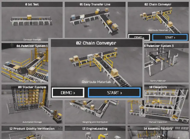
Start the EasyPLC Machine Simulator (MS). Select the start button on the main page or select machines from the main menu at the top of the machine’s simulator window.
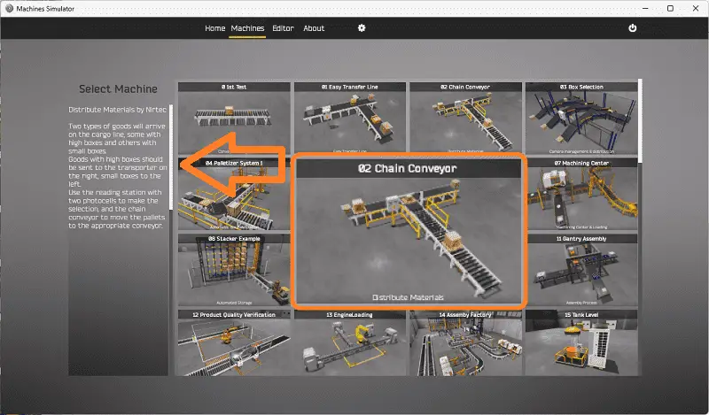
All the available machines will now be displayed. Click on the “02 Chain Conveyor”
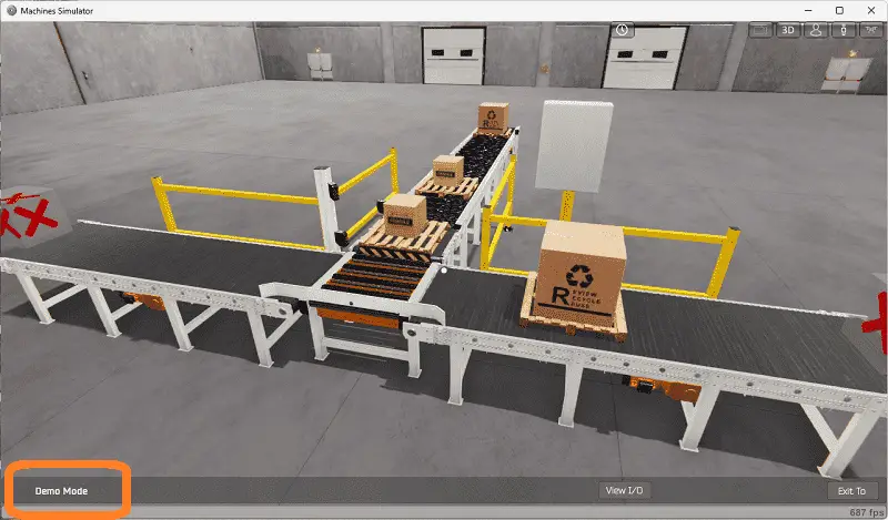
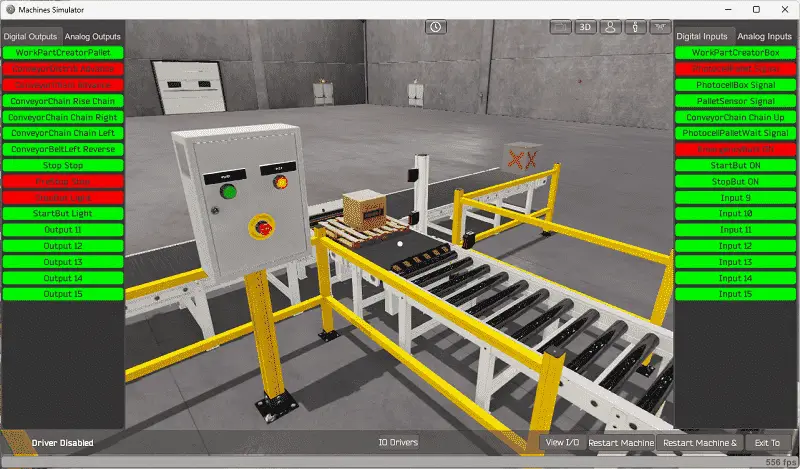
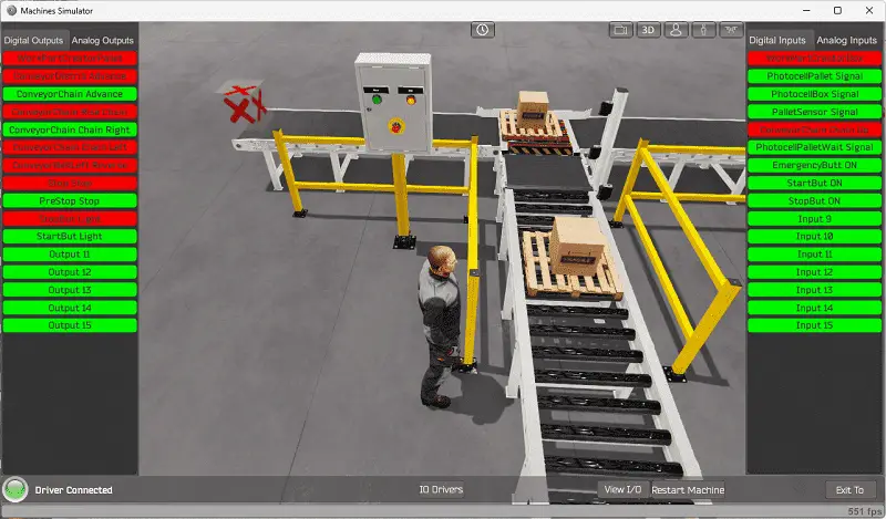
This is the example that we will be programming. To the left of the screen, information will be displayed on how this process needs to function.
Two goods will arrive on the cargo line, some with high boxes and others with small packages. Goods with high boxes should be sent to the transporter on the right and small boxes to the left. Use the reading station with two photocells to make the selection and the chain conveyor to move the pallets to the appropriate conveyor.
The green start light will be on when the system is ready to run. When the start is pressed, the stop light will be on to indicate how the system is stopped. Pressing the emergency stop button will turn off both lights and stop the sequence.
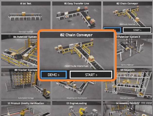
The machine simulator has a demo mode for the built-in machines. Select the demo mode. This will allow you to watch the operation of the easy transfer line and help see what must be done.
Move around the 3D virtual environment. The icons on the top of the window will allow you to move around this 3D environment.
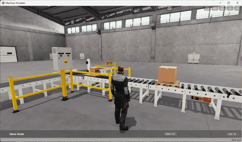
The first icon is the default selection. This will enable you to move around without bumping into the components. The first-person mode will mimic a person in your 3D learning world.
The third person is used to show the operator’s relationship to the machine. The last icon will automatically show you around this virtual environment. Once we understand what must be done, we can move on to the next step in our PLC program development.
Watch the sequence of operations in the video below.
Define the Inputs and Outputs: (Step 2 – Do-More Chain Conveyor Transfer)
Start the chain conveyor in start mode.
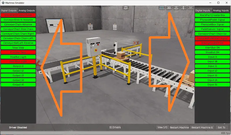
Select the View IO to display the inputs and outputs required for this machine.
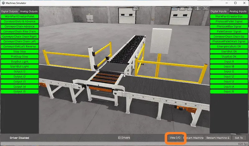
The chain conveyor transfer will require 11 digital outputs and nine digital inputs.
Clicking on the digital outputs will activate it. Spend time fully understanding the IO (inputs and outputs) functions.
You can move around in the 3D environment and see the IO and items from different angles.
The machine simulator will be communicating with a Do-More Designer PLC Simulator. Communication will be done with Modbus TCP (Ethernet).
The Do-More Series of PLCs use a fixed Modbus memory area. This area can be seen in the following chart.
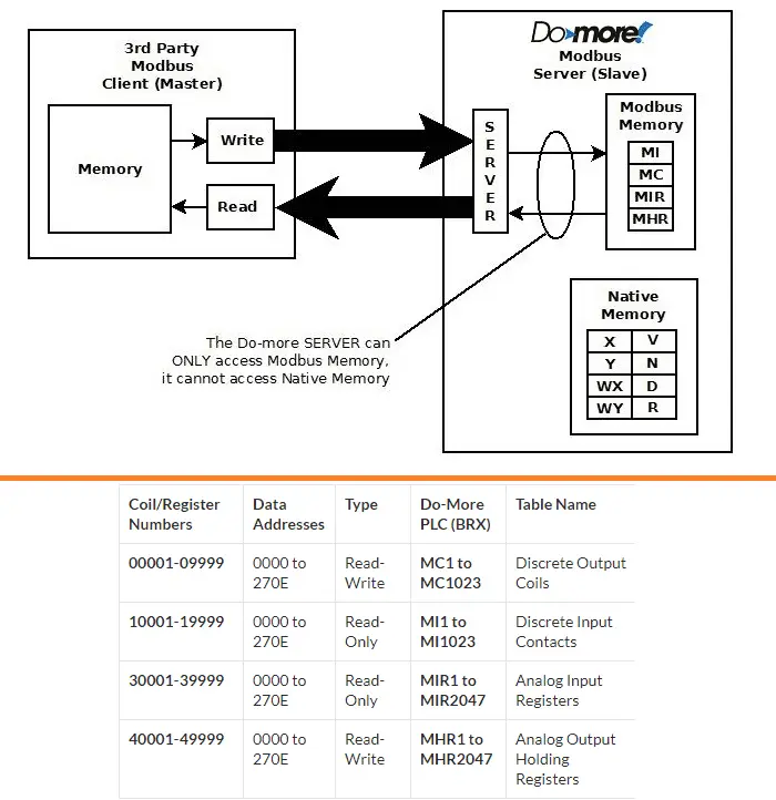
The following table will define the inputs and outputs (IO) and Modbus addresses in the Do-More PLC we will use for this program. (EasyPLC Chain Conveyor Transfer)
| Digital Type | Description | Do-More PLC Modbus Address | Machine Simulator Modbus Address |
| PLC Output – MS Input | Work Part Creator Pallet | MI1 – 10001 | 0 |
| PLC Output – MS Input | Conveyor Distribe Advance | MI2 – 10002 | 1 |
| PLC Output – MS Input | Conveyor Chain Advance | MI3 – 10003 | 2 |
| PLC Output – MS Input | Conveyor Chain Raise | MI4 – 10004 | 3 |
| PLC Output – MS Input | Conveyor Chain Right | MI1 – 10005 | 4 |
| PLC Output – MS Input | Conveyor Chain Left | MI2 – 10006 | 5 |
| PLC Output – MS Input | Conveyor Belt Left Reverse Exit | MI3 – 10007 | 6 |
| PLC Output – MS Input | Stop Stop | MI4 – 10008 | 7 |
| PLC Output – MS Input | PreStop Stop | MI1 – 10009 | 8 |
| PLC Output – MS Input | Stop Button Light | MI2 – 10010 | 9 |
| PLC Output – MS Input | Start Button Light | MI3 – 100011 | 10 |
| PLC Input – MS Output | Work Part Creator Box | MC1 – 1 | 0 |
| PLC Input – MS Output | Photocell Pallet Signal | MC2 – 2 | 1 |
| PLC Input – MS Output | Photocell Box Signal | MC3 – 3 | 2 |
| PLC Input – MS Output | Pallet Sensor Signal | MC4 – 4 | 3 |
| PLC Input – MS Output | Conveyor Chain Up | MC5 – 5 | 4 |
| PLC Input – MS Output | Photocell Pallet Wait Signal | MC6 – 6 | 5 |
| PLC Input – MS Output | Emergency Button | MC7 – 7 | 6 |
| PLC Input – MS Output | Start Button | MC8 – 8 | 7 |
| PLC Input – MS Output | Stop Button | MC9 – 9 | 8 |
Note: The machine simulator will be offset by one on the Modbus Addresses.
See the video below for the demo mode and determining inputs and outputs.
Develop a logical sequence of operation: (Step 3 – Do-More Chain Conveyor Transfer)
A flow chart or sequence table is used to understand the process that needs to be controlled thoroughly. It must also answer questions like the following:
What happens when electrical power and pneumatic air is lost? What happens when the input/output devices fail? Do we need redundancy?
This step is where you can save yourself a lot of work by understanding everything about the operation. It will help prevent you from continuously re-writing the PLC program logic. Knowing all of these answers upfront is vital in developing the PLC program.
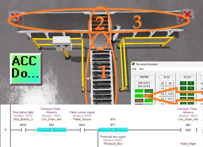
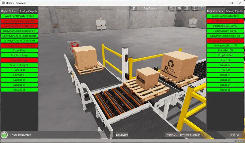
Our chain conveyor transfer can be seen as three different operations.
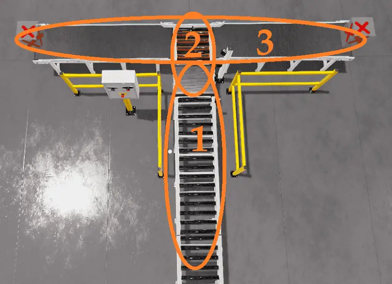
The conveyor distribution will create and put the skid on the belt. This skid will then be moved to the conveyor chain. Once on the conveyor chain, it will decide the right or left direction based on the photocell detecting height.
A PLC programmer must know how everything about the sequence and operation of the machine before programming.
Ask questions or view existing documentation to ensure you know the logical steps to the machine’s operation.
Develop the PLC program: (Step 4 – Do-More Chain Conveyor Transfer)
Writing the ladder logic code for the PLC example will be the next step in our program development.
The chain conveyor transfer starts and stops with a sealing circuit for the stop button light. Our stop button light contact will control the rest of the ladder.
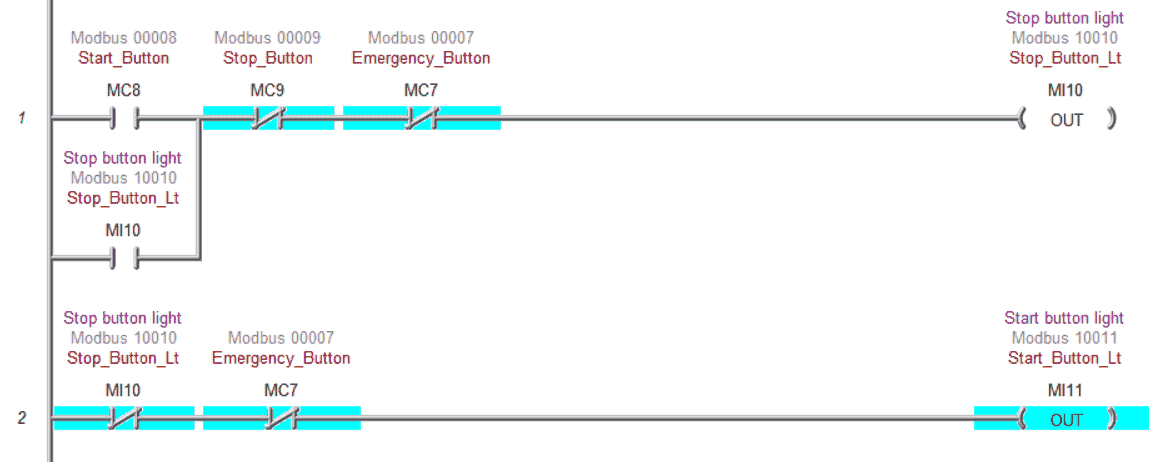
The start and stop lights are off when the emergency stop is activated. This indicates to the operator that the emergency stop must be reset.
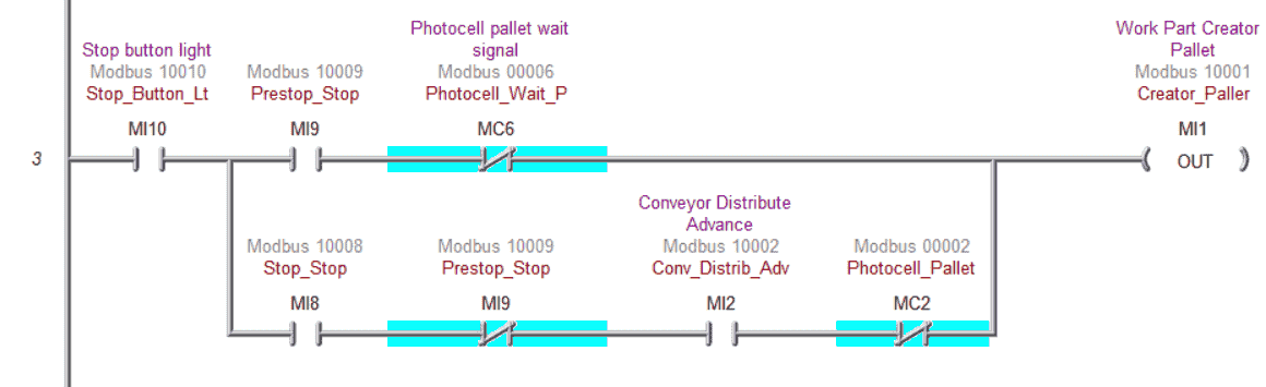
Here is the logic for the work part creation conveyor.
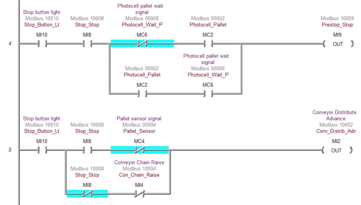
Prestop stop operation will control when the skid moves onto the belt conveyor. The conveyor distributes advance (belt conveyor) based on the pallet sensor and chain raise signal.
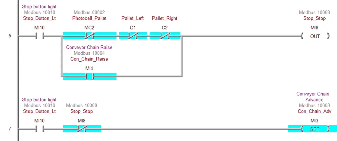
“Stop stop” (barrier) will separate the skids as they transfer from the belt to the chain conveyor. The conveyor chain advance will bring the pallet into the chain conveyor.
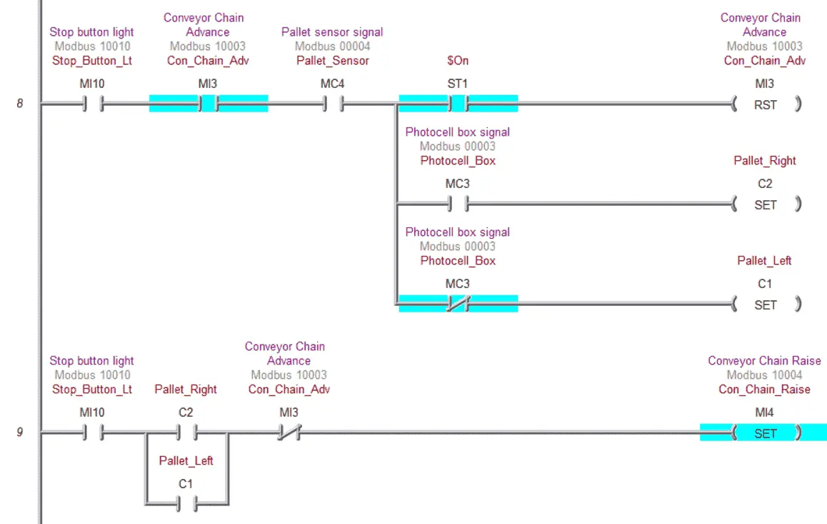
As the chain conveyor advances, the pallet sensor will activate. This will reset the chain conveyor advance and set the left or right pallet bits depending on the photocell box signal. Once it has been determined if the pallet is moving right or left, the conveyor chain rises.
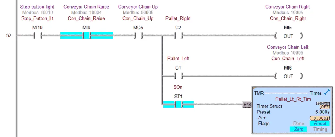
When the conveyor chain rising input is on, the pallet will move left or right, and a timer starts timing for 5 seconds. This timer is used to allow the pallet to move off of the conveyor chain.
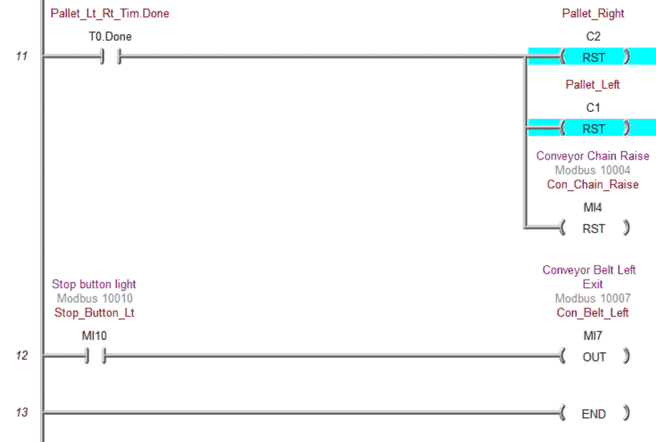
At the end of the 5 seconds timer, the pallet rise, left and right bits, are reset. The conveyor belt on the left and right will be on when the machine of running. This is the end of our program.
Ensure that the Do-More Designer PLC simulation is online. Transfer the program to the simulator and go into run mode. Select status on the main menu to see the active status of the inputs and outputs for our ladder logic.
Test the program: (Step 5 – Do-More Chain Conveyor Transfer)
We will use Modbus TCP on our Do-More Designer PLC simulator to communicate with the EasyPLC machine simulator.
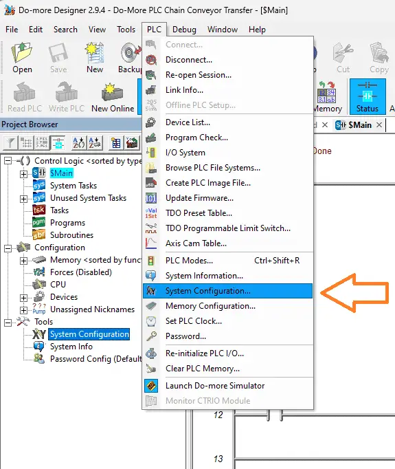
Select system configuration from the Project Browser under the Tools heading. You can also select this from the main menu | PLC | System Configuration…
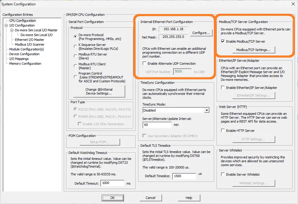
Under the Internal Ethernet Port Configuration, the IP address will be displayed. Since this is a PLC simulator, it is the same as your computer IP address. You will see the Modbus TCP Server configuration to the right of the port settings. This is enabled by default. The settings can be viewed under the Modbus TCP Settings button. We will leave these as their defaults.
Call up the Easy Transfer Line in start mode.
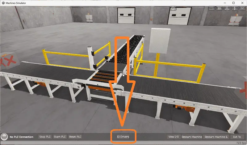
The status of the machine simulator will be at the bottom of the screen. Currently, we have no PLC connected. Select IO on the bottom middle of the screen.
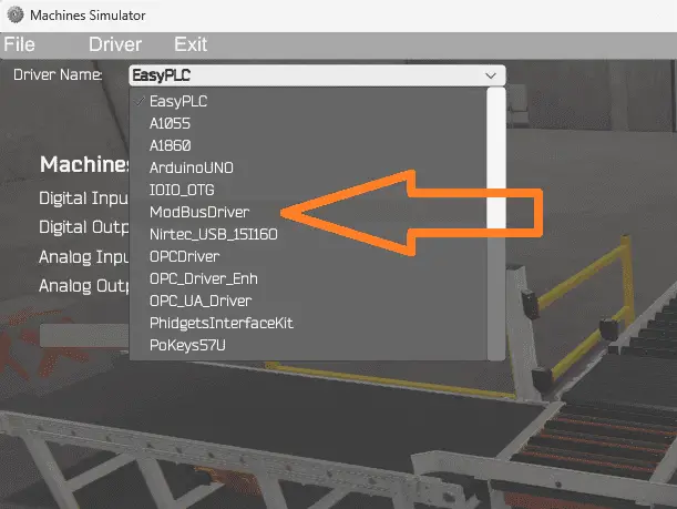
Under the driver pull-down menu, select “ModBusDriver.”
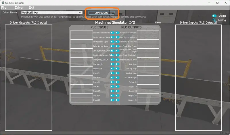
This driver will communicate Modbus TCP (Ethernet) and Modbus RTU (Serial). Select the configure button.
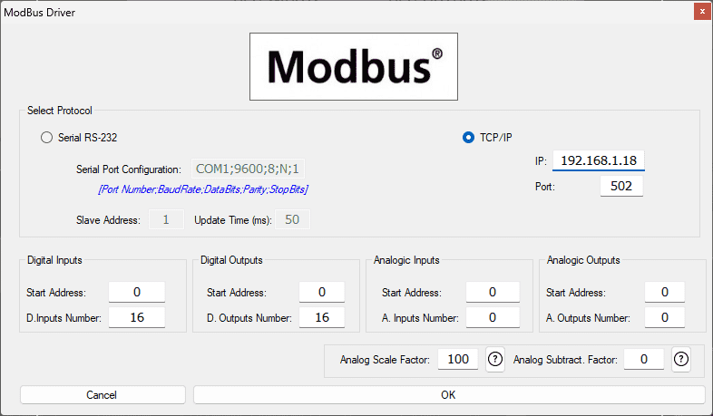
We can now enter the information for our Modbus driver. Select TCP/IP. This means the computer’s Ethernet port will communicate with the PLC. Enter the address of the PLC simulator (computer). The default port for Modbus TCP is 502.
The digital inputs from MS to the Do-More PLC Simulator will be MC1 to MC16. This will start at address 0 due to the offset of 1. Digital outputs from MS to the Do-More PLC Simulator will be MI1 to MI16. This will begin at address 0 due to the offset of 1. No errors will occur if we set the number of inputs and outputs higher than we require.
Select the OK button.
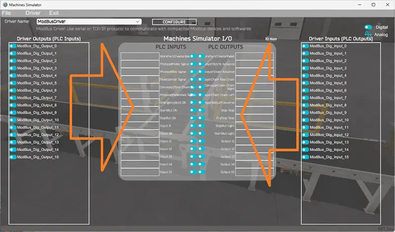
You will now see the inputs and outputs specified for the Modbus driver. We can now manually assign the driver outputs to the PLC and driver inputs to the PLC outputs. To save time, we can use an automatic assignment for this operation. Ensure that the IO is in the same order as the EasyPLC simulators.
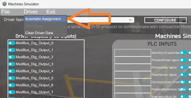
Select Automatic Assignment from the driver option in the main menu.
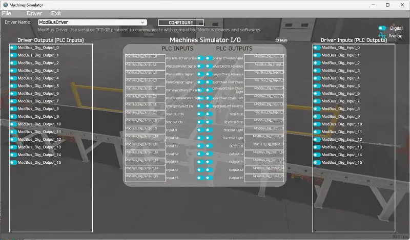
This will automatically assign the PLC IO to the Machine Simulator IO.
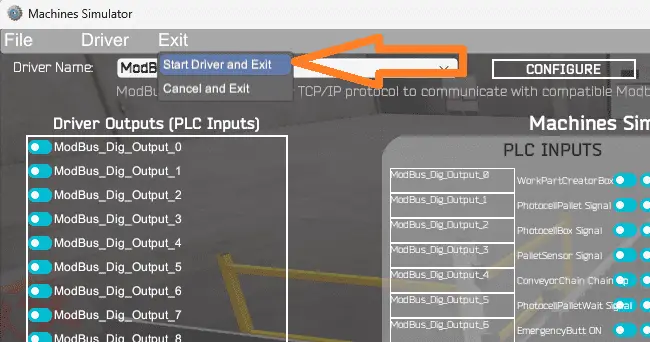
Select start driver and exit from the main menu.
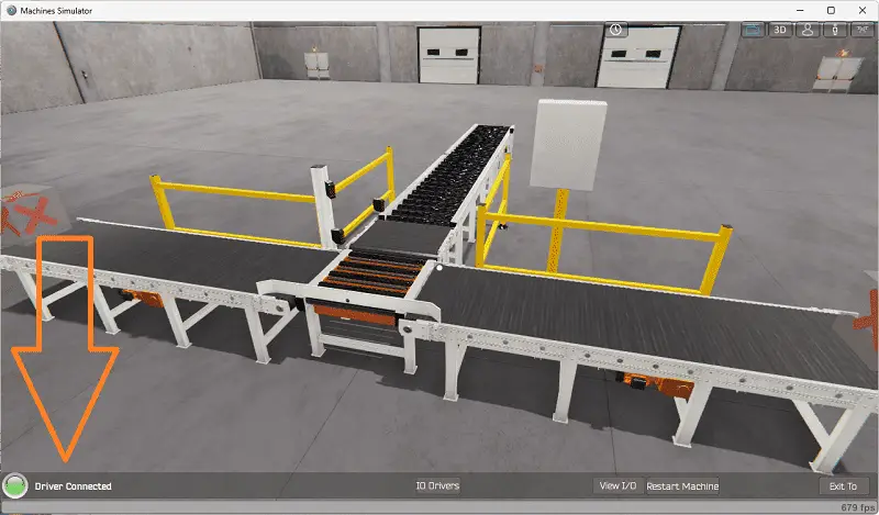
You will see that the driver is operating on the bottom left side of the window.
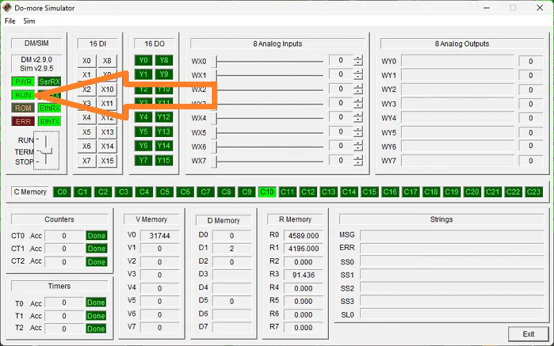
Ensure that the PLC simulator is in Run mode. If not, then move the toggle switch to RUN.
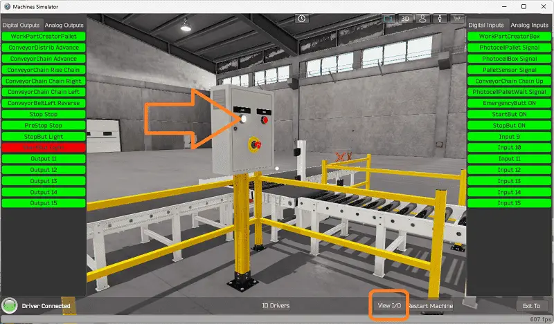
Select view IO to know the input and output status of the machine simulator. Press the lighted green button on the control panel to start the chain conveyor transfer machine.
Move around and test our program for all possible events.
Using Machine Simulator (MS) to test the program will ensure that our program works. The EasyPLC machine simulator is the easiest way to learn PLC programming.
Download the Do-More PLC sample program for the chain conveyor transfer here.
Watch the video below to see the five steps of program development applied to the chain conveyor transfer.
EasyPLC Software Suite is a complete PLC, HMI, and Machine Simulator package. This PLC learning package includes the following:
Easy PLC – PLC Simulation allows programming in Ladder, Grafcet, Logic Blocks, or Script.
HMI System – Easily create a visual human-machine interface (HMI)
Machine Simulator – A virtual 3D world with real-time graphics and physical properties. PLC programs can be tested using EasyPLC or through other interfaces. (Modbus RTU, TCP, etc.)
Machine Simulator Lite – Designed to run on Android Devices.
Machine Simulator VR – Virtual Reality comes to life so you can test, train or practice your PLC programming.
Purchase your copy of this learning package for less than USD 75 for a single computer install or less than USD 100 to allow different computers.
Receive 10% off the price by typing in ACC in the comment section when you order. http://www.nirtec.com/index.php/purchase-price/
Learn PLC programming the easy way. Invest in yourself today.
Watch on YouTube: Programming Chain Conveyor Transfer with Do-More
If you have any questions or need further information, please contact me.
Thank you,
Garry
If you’re like most of my readers, you’re committed to learning about technology. Numbering systems used in PLCs are not challenging to learn and understand. We will walk through the numbering systems used in PLCs. This includes Bits, decimals, Hexadecimal, ASCII, and Floating points.
To get this free article, subscribe to my free email newsletter.
Use the information to inform other people how numbering systems work. Sign up now.

The ‘Robust Data Logging for Free’ eBook is also available for free download. The link is included when you subscribe to ACC Automation.