A dusk to dawn sensor usually is discrete on/off of the lighting control. If we want to vary the lights to mimic more of the sunset and rise, we would use an analog output to control the lights. I was recently asked about such a program. Every day they wanted the lights to go off at 10 pm and come back on at 6 am. At 9:30 pm the lights would be on at 70% or 7volts of a 0-10V signal. In the next half hour, the program will bring the lights from 70% down to 0%. In the morning the lights will come back on within the half-hour from 0% to 70%. Poultry Farms are one place that would utilize this program.
We will be developing a program that will do this with our BRX PLC (Do-More). Let’s get started!
Previously in this BRX series PLC, we have discussed:
System Hardware – Video
Unboxing – Video
Installing the Software – Video
Establishing Communication – Video
Firmware Update – Video
Numbering Systems and Addressing – Video
First Program – Video
Monitoring and Testing the Program – Video
Online Editing and Debug Mode – Video
Timers – Video
Counters – Video
High-Speed IO – Video
Compare Instructions – Video
Math Instructions – Video
Program Control – Video
Shifting Instructions – Video
Drum Instruction – Video
Serial Communication – Modbus RTU to Solo Process Temperature Controller – Video
Data Logging – Video
Email – Text SMS Messaging Gmail – Video
Secure Email Communication Video
AdvancedHMI Communication – Modbus TCP – Video
Analog IO – System Configuration – Video
HTTP JSON Instructions – Video
Our entire series can be found here.
https://accautomation.ca/series/brx-do-more-plc/
The programming software and manuals can be downloaded from the Automation Direct website free of charge.
Watch the video below to see the Analog Dust to Dawn program in action on our BRX PLC.

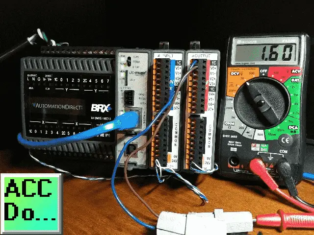
Hardware – BRX Do-More PLC
The hardware that we are using can be found in the BRX series mentioned above.
Analog Output – BRX Do-More
In the explanation above we are changing the analog output from 0 to 7 volts in 30 minutes or (30 Minutes x 60 Seconds) 1800 seconds. Every second we will adjust our analog output.
We need to scale the analog output so that 1800 seconds will give us 7 VDC.
1800 Seconds / 7 VDC = ? Seconds / 10VDC
1800 Seconds x 10 VDC / 7 VDC = 2571 Seconds
In our example, 0 – 10 VDC will be scaled in the plc 0 – 2571. Each second the analog output will be increased or decreased by 10VDC / 2571 Seconds = 0.00389 VDC
Configuring the Analog Output
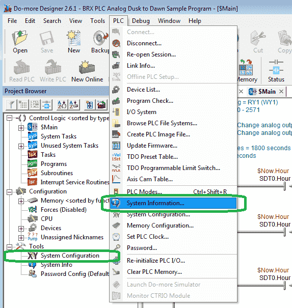
In the Do-More Designer software, select System Configuration under the Tools heading in the Project Browser window. You can also use the main menu | PLC | System Configuration…
Select Module Configuration(s)
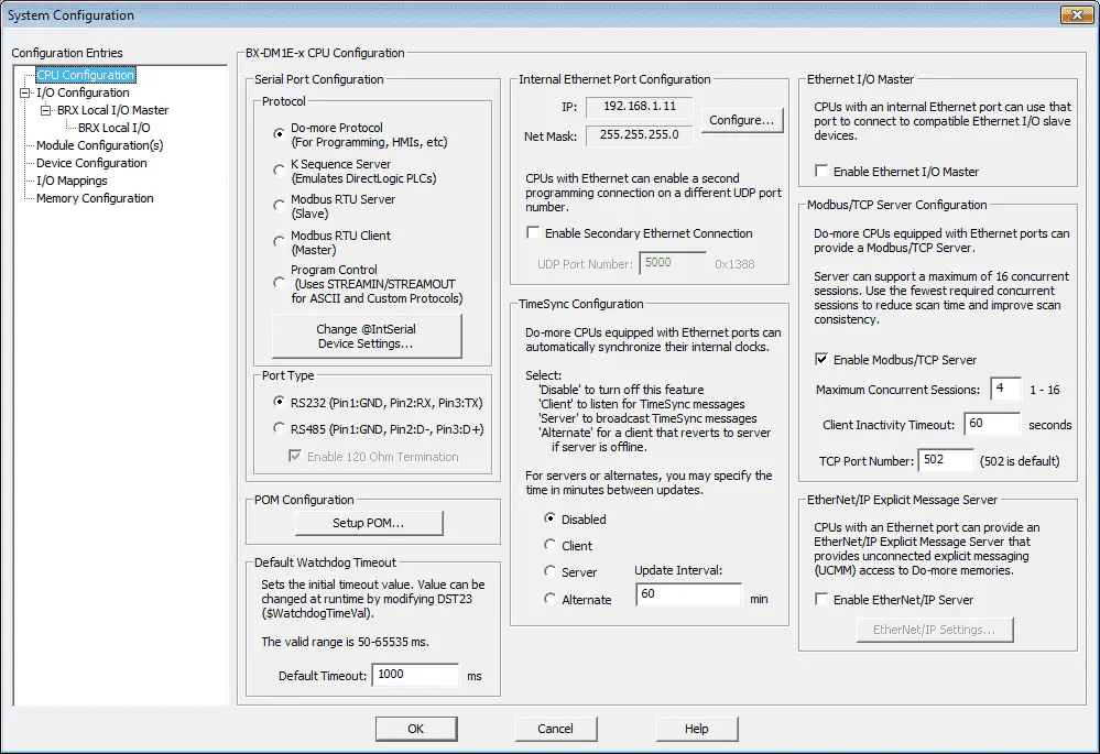
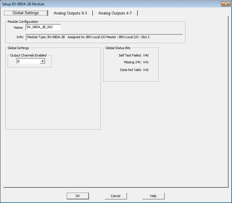
Select the analog output card BX-08DA-2B. This is located in slot 2.
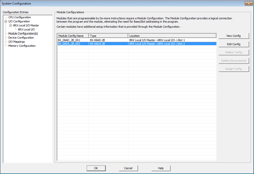
Select the ‘Edit Config’ button.
Select the Analog Output 0-3 tab.
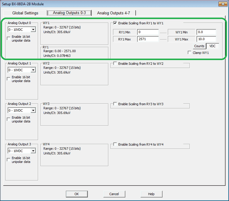
We will use Analog Output 0 for our analog signal. This will be set for Data Register RY1. Our scaling range will be 0 to 2571 = 0 V to 10.0 V.
Select OK.
The configuration of our analog output is now complete.
BRX Do-More Ladder Program Example
The real-time clock (RTC) in the BRX PLC will write to the $Now memory area. We will compare this memory area for the hours and minutes of the day.
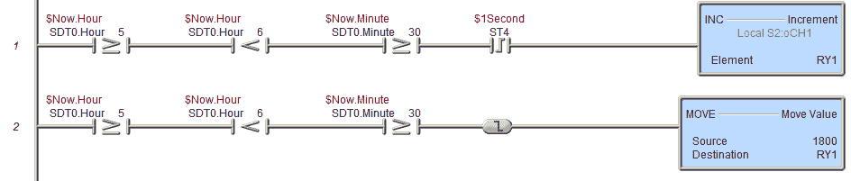
If the $Now.Hour (24 Hour) is greater or equal to 5 (5 am), and less than 6 (6 am), and the $Now.Minutes are greater or equal to 30, we will increment the analog output (RY1). This will happen on the leading edge of the 1-second pulse bit to slowly turn on the lights.
On the trailing edge of these input conditions, the value 1800 is written to RY1 to ensure that after 6 am the lights are on.
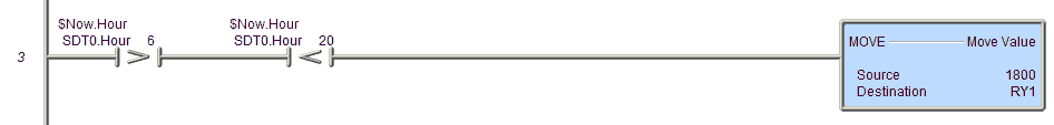
If the $Now.Hour (24 Hour) is greater than 6 (6 am) and less than 20 (8 pm) then move 1800 into the analog output (RY1). This will ensure the lights are on after 6 am and before 8 pm.
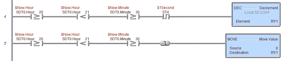
If the $Now.Hour (24 Hour) is greater or equal to 20 (8 pm), and less than 21 (9 pm), and the $Now.Minutes are greater or equal to 30, we will decrement the analog output (RY1). This will happen on the leading edge of the 1-second pulse bit to slowly turn off the lights.
On the trailing edge of these input conditions, the value 0 is written to RY1 to ensure that after 9 pm the lights are off.
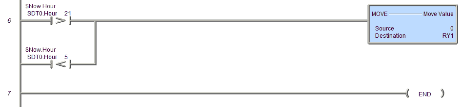
If the $Now.Hour (24 Hour) is greater than 21 (9 pm) or less than 5 (5 am) then move 0 into the analog output (RY1). This will ensure the lights are off after 9 pm and before 5 am.
Testing the ladder logic
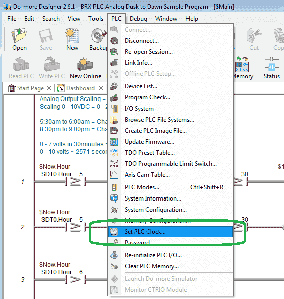
We can now connect and download our program to the PLC. Instead of waiting for the time to happen on our circuit, we can manually set the RTC on our PLC.
Select ‘Set PLC Clock…’ from the main menu | PLC of the Do-More Designer Software.
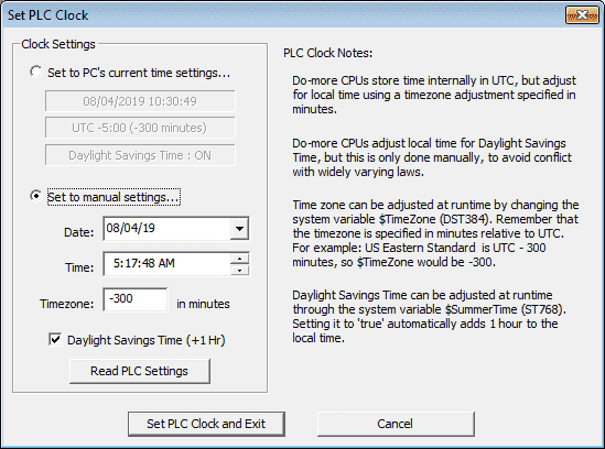
We can then write the time that we want in the PLC RTC.
Select the ‘Set PLC Clock and Exit’ button when you want to set this time.
Watch the video below to see the Analog Dust to Dawn program in action on our BRX PLC.
You can download the program here.
BRX Do-More Series PLC from Automation Direct – Power to deliver
Overview Link (Configure and purchase a system)
Manuals and Product Inserts (Installation and Setup Instruction)
Do-More Designer Software v2.0.3 (Free Download Link) – The software will contain all of the instruction sets and help files for the BRX Series PLC.
Watch on YouTube : BRX PLC Analog Dusk to Dawn Program
If you have any questions or need further information please contact me.
Thank you,
Garry
If you’re like most of my readers, you’re committed to learning about technology. Numbering systems used in PLC’s are not difficult to learn and understand. We will walk through the numbering systems used in PLCs. This includes Bits, Decimal, Hexadecimal, ASCII, and Floating Point.
To get this free article, subscribe to my free email newsletter.
Use the information to inform other people how numbering systems work. Sign up now.

The ‘Robust Data Logging for Free’ eBook is also available as a free download. The link is included when you subscribe to ACC Automation.