A dusk to dawn sensor usually is discrete on/off of the lighting control. If we want to vary the lights to mimic more of the sunset and rise, we would use an analog output to control the lights. I was recently asked about such a program. Every day they wanted the lights to go off at 10 pm and come back on at 6 am. At 9:30 pm the lights would be on at 70% or 7volts of a 0-10V signal. In the next half hour, the program will bring the lights from 70% down to 0%. In the morning the lights will come back on within the half-hour from 0% to 70%. Poultry Farms are one place that would utilize this program.
We will be developing a program that will do this with our Click PLC. Let’s get started!
Previously in this series, we have discussed:
System Hardware – Video
Installing the Software – Video
Establish Communication – Video
Numbering System and Addressing – Video
Timers and Counters
– Counter Video
– Timer Video
Compare and Math Instructions – Video
Program Control Instructions – Video
Shift Register – Video
Drum Instruction – Video
Send and Receive Instructions – Video
AdvancedHMI Communication – Video
Firmware Update – Video
HMI Rotary Encoder Dial Input – Video
High Speed Counters Part 1
– High-Speed Count Mode Video
– Interval Measurement Mode Video
– Duration Measurement Mode Video
– Frequency Measurement Mode Video
High Speed Counters Part 2
– External Interrupt Mode Video
– Pulse Catch Mode Video
– Filter Pulse Mode Video
– Frequency Measurement and High-Speed Count Mode Video
Wiring Stack Light to Click PLC – Video
Wiring Push Buttons and Selector Switch to Click PLC – Video
– Test and Assembly of Push Buttons and a Selector Switch – Video
Wiring an Inductive Proximity NPN PNP Sensor to the Click PLC – Video
Wiring a Capacitive Proximity NPN PNP Sensor to the Click PLC – Video
Wiring an Ultrasonic Proximity Sensor to the Click PLC – Video
– Unboxing our UK1F Ultrasonic Proximity Sensor – Video
Our entire series can be found here.
https://accautomation.ca/series/click-plc/
The programming software and manuals can be downloaded from the Automation Direct website free of charge.
Watch the video below to see the Analog Dust to Dawn program in action on our Click PLC.

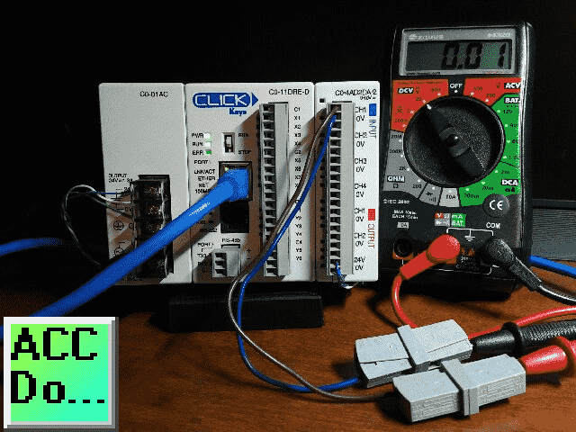
Hardware
Our hardware includes the following:
C0-11DRE-D – Click CPU with Ethernet
Note: Click Ethernet CPU with analog is also available.
C0-4AD2DA-2 – Click Analog Card 4 inputs / 2 outputs
C0-01AC – Click 24VDC power supply
Analog Output
In the explanation above we are changing the analog output from 0 to 7 volts in 30 minutes or (30 Minutes x 60 Seconds) 1800 seconds. Every second we will adjust our analog output.
We need to scale the analog output so that 1800 seconds will give us 7 VDC.
1800 Seconds / 7 VDC = ? Seconds / 10VDC
1800 Seconds x 10 VDC / 7 VDC = 2571 Seconds
In our example, 0 – 10 VDC will be scaled in the plc 0 – 2571. Each second the analog output will be increased or decreased by 10VDC / 2571 Seconds = 0.00389 VDC
Configuring the Analog Output
In the Click PLC programming software, select System Configuration under the Function tab of the Navigation window. You can also use the main menu | Setup | System Configuration…
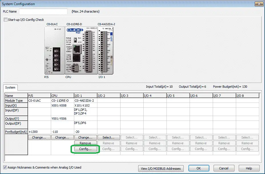
Select Config…
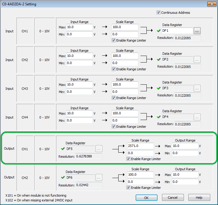
We will use Output CH1 for our analog signal. This will be set for Data Register DF5. Our scaling range will be 2571 to 0 = 10.0 V to 0 V.
Select OK.
The configuration of our analog output is now complete.
Ladder Program – Click PLC Analog Example
The real-time clock (RTC) in the Click PLC will write to the SD memory area. We will compare this memory area for the hours and minutes of the day.

If the RTC_Hour (24 Hour) is greater or equal to 5 (5 am), and less than 6 (6 am), and the RTC_Minutes are greater or equal to 30, we will increment the analog output (DF5). This will happen on the leading edge of the 1-second pulse bit.
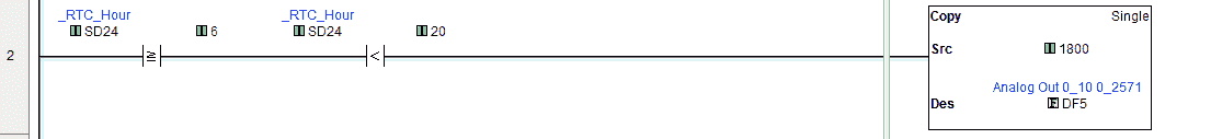
If the RTC_Hour (24 Hour) is greater or equal to 6 (6 am) and less than 20 (8 pm) then move 1800 into the analog output (DF5). This will ensure that the lights are on during this time.

If the RTC_Hour (24 Hour) is greater or equal to 20 (8 pm), and less than 21 (9 pm), and the RTC_Minutes are greater or equal to 30, we will decrement the analog output (DF5). This will happen on the leading edge of the 1-second pulse bit. The lights will now start to dim.
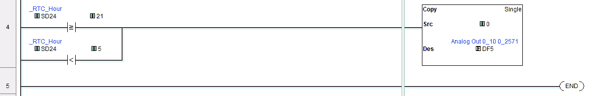
If the RTC_Hour (24 Hour) is greater or equal to 21 (9 pm) or less than 5 (5 am) then move 0 into the analog output (DF5). This will ensure that the lights are off during this time.
Testing the ladder logic – Dusk to Dawn Program
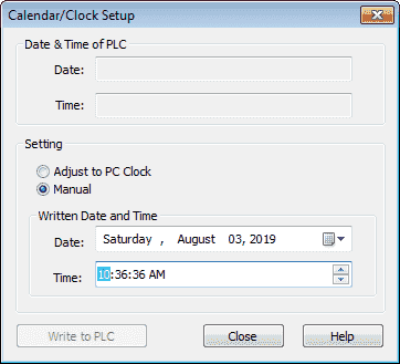
We can now connect and download our program to the PLC. Instead of waiting for the time to happen on our circuit, we can manually set the RTC on our PLC.
Select Calendar / Clock Setup… from the main menu | PLC of the Click Programming Software. We can then write the time that we want in the PLC RTC.
Select the ‘Write to PLC’ button when you want to set this time.
Watch the video below to see the Analog Dust to Dawn program in action on our Click PLC.
Download the Click PLC program here.
Click PLC Support Links
The Click PLC can be programmed using free Click programming software from Automation Direct. Here is a link for the software.
https://support.automationdirect.com/products/clickplcs.html
The following links will help you to install the software and establish communication.
https://accautomation.ca/click-plc-installing-the-software/
https://accautomation.ca/click-plc-establish-communication/
The entire Click PLC series can be found at the following URL:
https://accautomation.ca/series/click-plc/
Watch on YouTube: Click PLC Analog Dusk to Dawn Program
If you have any questions or need further information please contact me.
Thank you,
Garry
If you’re like most of my readers, you’re committed to learning about technology. Numbering systems used in PLC’s are not difficult to learn and understand. We will walk through the numbering systems used in PLCs. This includes Bits, Decimal, Hexadecimal, ASCII and Floating Point.
To get this free article, subscribe to my free email newsletter.
Use the information to inform other people how numbering systems work. Sign up now.

The ‘Robust Data Logging for Free’ eBook is also available as a free download. The link is included when you subscribe to ACC Automation.