We will now configure and operate Analog inputs and outputs on our BRX Do-More controller. One of the features of the BRX Series PLC is the ability to expand its capability to fit your application. This is easily done by “snap-on” modules that will fit on the side of the BRX MPU (Multi-Processor Unit). As we have seen before in the BRX PLC System Configuration post we can add additional discrete inputs and outputs. Automation Direct now offers Analog Voltage and Analog Current input and output modules. These modules come as an 8 point channel unit. There is also a 4 point thermocouple input module also available. We will be configuring, scaling and programming the Analog input and output Voltage modules for our BRX PLC. Let’s get started.
Previously in this BRX series PLC, we have discussed:
System Hardware – Video
Unboxing – Video
Installing the Software – Video
Establishing Communication – Video
Firmware Update – Video
Numbering Systems and Addressing – Video
First Program – Video
Monitoring and Testing the Program – Video
Online Editing and Debug Mode – Video
Timers – Video
Counters – Video
High-Speed IO – Video
Compare Instructions – Video
Math Instructions – Video
Program Control – Video
Shifting Instructions – Video
Drum Instruction – Video
Serial Communication – Modbus RTU to Solo Process Temperature Controller – Video
Data Logging – Video
Email – Text SMS Messaging Gmail – Video
AdvancedHMI Communication – Modbus TCP – Video
Configuring a BRX Do-More Series PLC
Configuring a BRX Do-More PLC is easy with the online configuration support.
https://www.automationdirect.com/do-more/brx/config
Choose the CPU to get started. In our case, we will start with the 18-Series that includes the Ethernet.

Click the Configure an 18-Series Ethernet Model Now button.
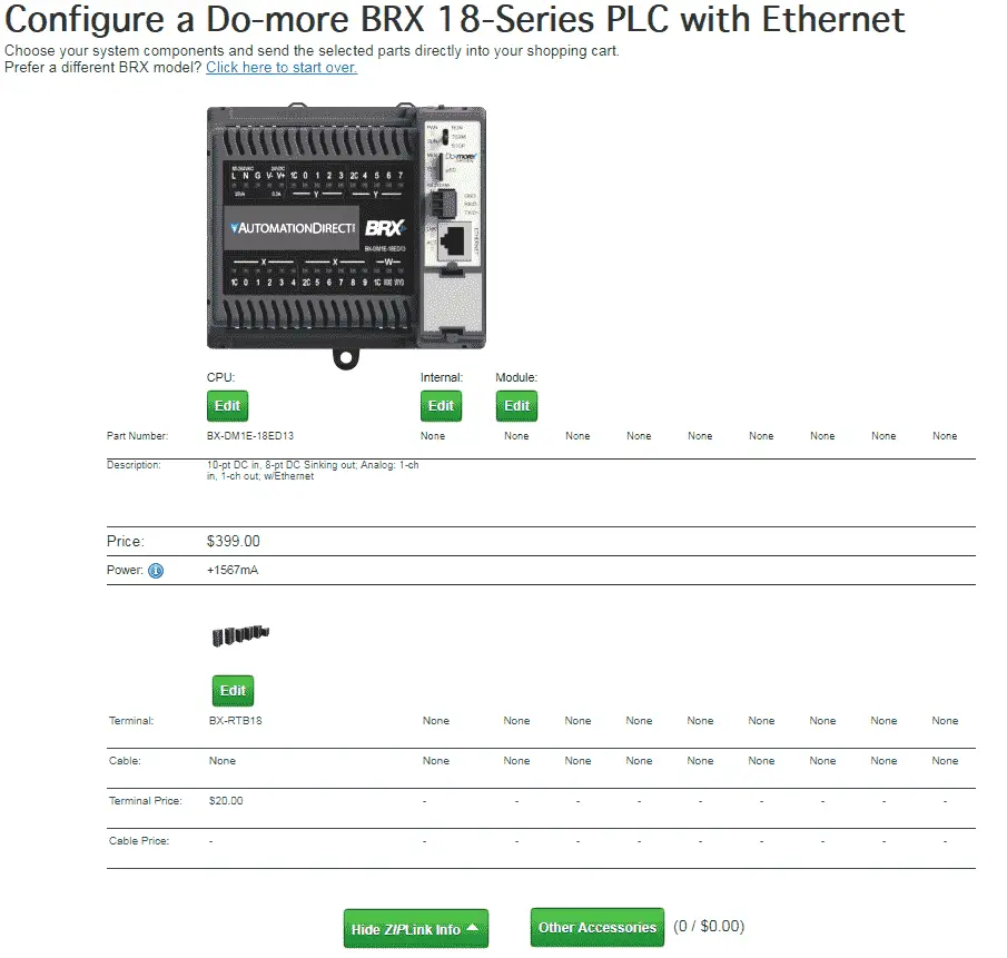
You will now see the basic configuration of the system. Hitting the Edit button under the CPU will allow you to change the CPU model number. Our current model number is BX-DM1E-18ED13.
All BRX I/O modules require 24VDC to operate. The main CPU will have a built-in 24VDC supply. This is shown under Power below the CPU. In our case, we have a 1567mA supply to power our expansion cards and some sensors.
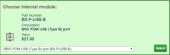
We will click on Edit under Internal for the CPU and add a BRX POM USB for programming the unit. (Pluggable Option Module) See the following post for more information.
https://accautomation.ca/brx-plc-system-hardware/
Hit the select button to return this option to the configuration menu.

Add an 8 channel Analog Input Voltage card to module 1 of our system and hit select.

Add an 8 channel Analog Output Voltage card to module 2 of our system and hit select.
Our complete system is now configured.
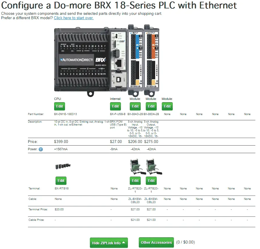
Each of the I/O and option devices added will show the amount of power that they will require.
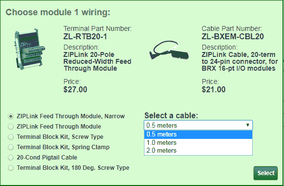
We have options to change the wiring options for each of the expansion IO and CPU unit. Selecting the option will change the configuration for you automatically.
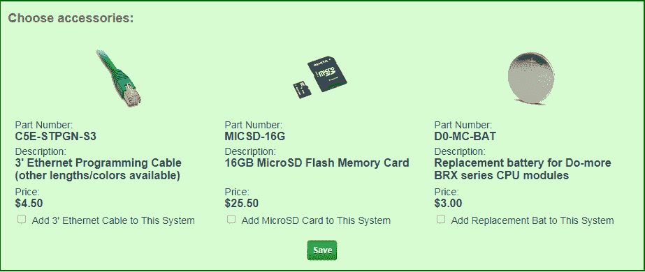
Under other accessories you can select Ethernet cable, SD Memory card or replacement batteries for the CPU.
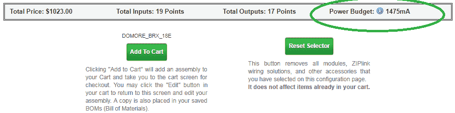
Once you complete your configuration you can then review the price, inputs, outputs and power. In our case after the cards have been powered, we will still have 1475mA to power other external input and output devices for our automated system.
Analog Input and Output Voltage – BRX Do-More
Data Range Specifications
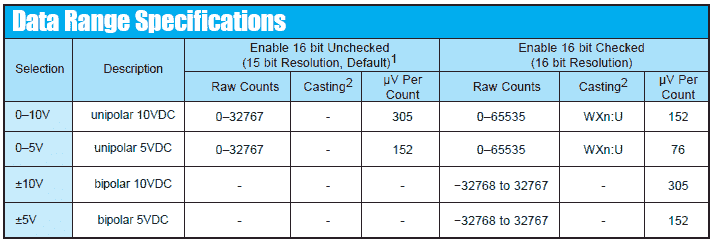
Note: You can have 15 or 16-bit resolution on the unipolar 0-10V or 0-5V selections. The bipolar ranges will automatically be a 16-bit resolution.
Casting is required when using a 16-bit resolution on unipolar.
Example: WXn:U
– WXn is the channel to look at
– :U cast to an unsigned integer value (signed is the default)
The following post will go over the numbering systems of the BRX PLC:
https://accautomation.ca/brx-plc-numbering-systems-and-addressing/
Module Installation – BRX Do-More Analog
Power must be turned off of the PLC system before the BRX expansion modules are installed. (They are NOT hot-swappable.)
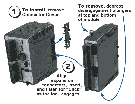
To install the module, remove the connector cover on the right side of the BRX MPU or expansion module. Align the expansion connectors and insert the module until you hear a “click”. This indicates that the expansion connectors have engaged.
To remove the expansion module, depress the two plungers on the top and bottom of the card. This will release the locking mechanism and disengage the unit from the system.
Let’s go online now with our controller and call up the dashboard. This will now show us a graphical image of our system.

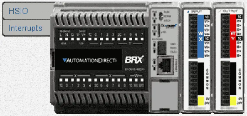
The input and output channels for our analog input and output cards have automatically been set. We will need to just verify and set our scaling factors.
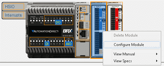
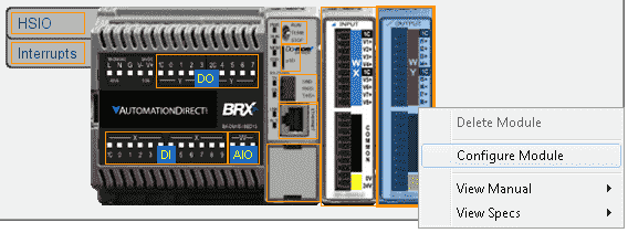
Right-click on the analog input module and select Configure Module.
Notice that you can also view the manual and specifications from this menu. The website information will be displayed or downloaded for your convenience.
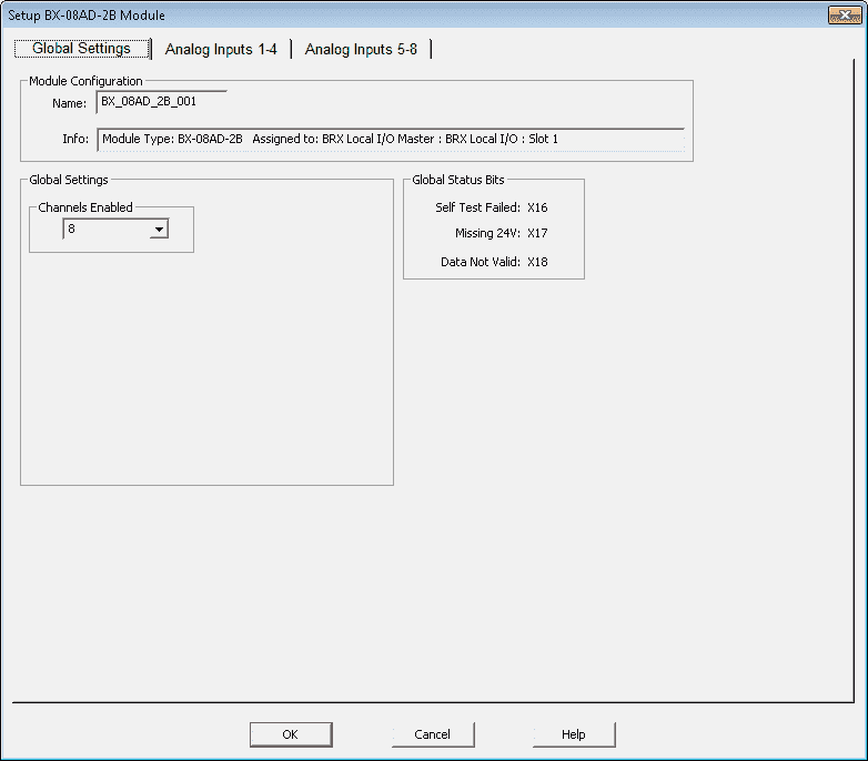
This will now bring up the configuration window for our module.
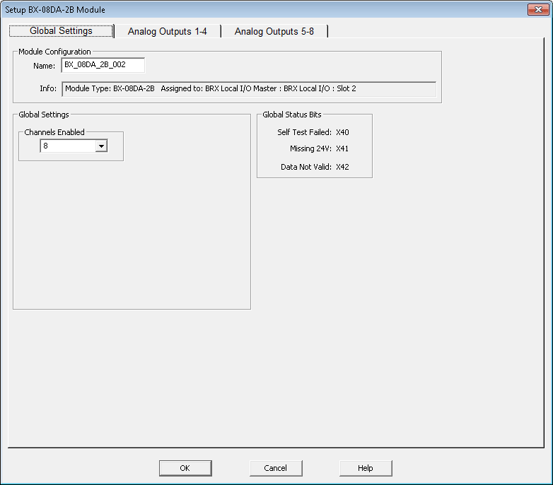
Global Settings
Module Configuration – The name and information of the module installed will be displayed.
Global Settings – Here we can enable the channels of the card. We will leave all of the channels enabled for our setup.
Global Status Bits – These three bits will relate to the operation of the module. We have a self-test failed, missing 24VDC, and a data not a valid bit. We will use these bits in our program to ensure that the module is functioning correctly.
Click on the Analog Inputs 1-4 tab along the top of the window.
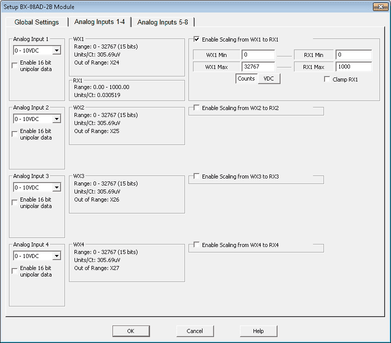
We will set up scaling for the first input of the analog input module. Click on “Enable Scaling form WX1 to RX1”. You will now see the areas in which we can place our scaling values. RX1 Min will be 0 and RX1 Max will be 1000. This will be for our full range of the analog signals. WX1 Min – 0 to WX1 Max 32767.
We will leave the default input range as 0- 10VDC.
Click OK at the bottom of the window to save and close.
Right click on the analog output module and select Configure Module from the dashboard.
This will now bring up the configuration window for our module.
Global Settings
Module Configuration – Name and information of the module installed will be displayed.
Global Settings – Here we can enable the channels of the card. We will leave all of the channels enabled for our setup.
Global Status Bits – These three bits will relate to the operation of the module. We have a self test failed, missing 24VDC and a data not valid bit. We will use these bits in our program to ensure that the module is functioning correctly. Note: This is similar to the analog input card.
Click on the Analog Outputs 1-4 tab along the top of the window.
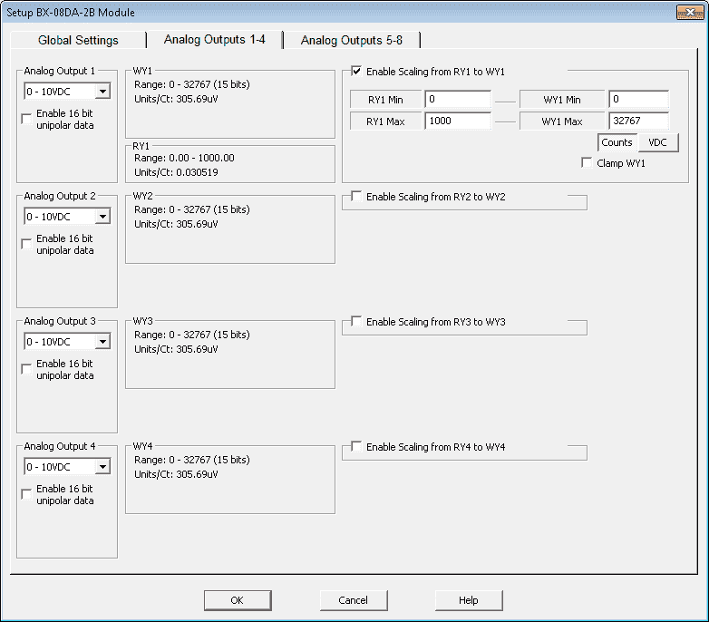
We will set up scaling for the first output of the analog output module. Click on “Enable Scaling form RY1 to WY1”. You will now see the areas in which we can place our scaling values. RY1 Min will be 0 and RY1 Max will be 1000. This will be for our full range of analog output signal. WY1 Min – 0 to WY1 Max 32767
We will leave the default output range as 0- 10VDC.
Click OK at the bottom of the window to save and close
Sample PLC Program – BRX Do-More Analog
We can now program our BRX Series PLC.
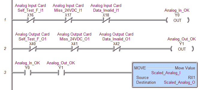
The input module bits are used to ensure that the input and output analog modules are working correctly. They will turn on Y0 and Y1 respectfully.
If the modules are working correctly the scaled input RX1 will be moved to the scaled output RY1.
We will be testing our analog input with the 9V battery tester we have made earlier.
https://accautomation.ca/create-an-analog-voltage-input-tester-for-a-plc/
The output from the analog will be tested with a multimeter.
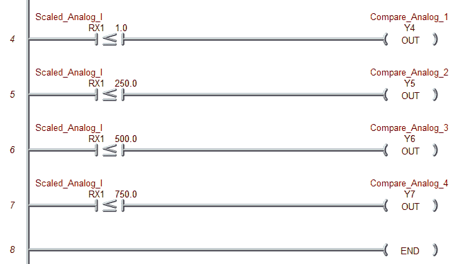
We will also compare the analog input to some predetermined values and trigger individual bits on our BRX Series PLC outputs.
See the video below to watch how easy it is to configure, scale and program these analog cards in the BRX Series PLC.
You can download the program here.
BRX Series PLC from Automation Direct – Power to deliver
Overview Link (Configure and purchase a system)
Manuals and Product Inserts (Installation and Setup Instruction)
Do-More Designer Software v2.0.3 (Free Download Link) – The software will contain all of the instruction sets and help files for the BRX Series PLC.
Watch on YouTube : BRX PLC Analog IO – System Configuration
If you have any questions or need further information please contact me.
Thank you,
Garry
If you’re like most of my readers, you’re committed to learning about technology. Numbering systems used in PLC’s are not difficult to learn and understand. We will walk through the numbering systems used in PLCs. This includes Bits, Decimal, Hexadecimal, ASCII and Floating Point.
To get this free article, subscribe to my free email newsletter.
Use the information to inform other people how numbering systems work. Sign up now.

The ‘Robust Data Logging for Free’ eBook is also available as a free download. The link is included when you subscribe to ACC Automation.