The Click PLC has automatic linear scaling for the analog inputs and outputs. What if the analog input or output is not linear? How do you handle this in the PLC? Look at the following tank. We can measure the height, which is linear, but the volume will not because of the shape of the tank.
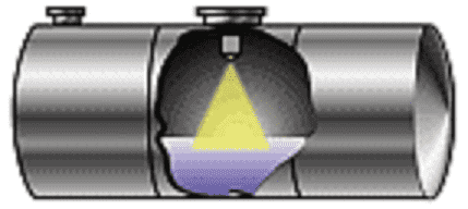 We will look at an application to determine the volume in this tank. This will be based on the height of the liquid in the tank. We will then scale this non-linear volume of the tank to display the actual volume. Let’s get started.
Our entire Click series can be found here. All the previous information for the Click PLC can be applied to the Click PLUS.
Previously we looked at the following:
Software Installation – Video
Click Software Establish Communication – Video
MQTT Communication – Video
Data Logging – Video
Click Plus Real-Time Clock – Video
Serial Communication Timing – Video
Retentive Data Memory Registers – Video
The programming software and manuals can be downloaded from the Automation Direct website.
Watch the video below to see the setup, linear, and non-linear analog input programming of the Click PLC using the Click programming software.
What are Analog Signals?
Analog signals refer to a measurement range instead of a discrete on/off signal. This range can represent many things like speed, distance, pressure, etc. In our application, the analog input signal will be the level in a tank.
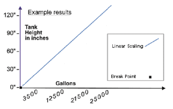
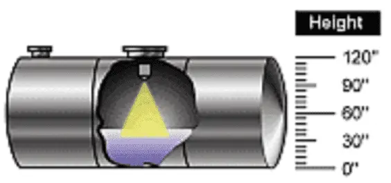 The sensor in the tank will read the level of liquid. This is linear from 0 to 120 inches. Linear means that if we were to plot this on a graph, the line would be straight.
Click PLC Analog Specifications
We are using a Click PLC C2-08DR-4VC discrete and analog combination module. Looking at the analog input specifications for voltage, we can see the following:
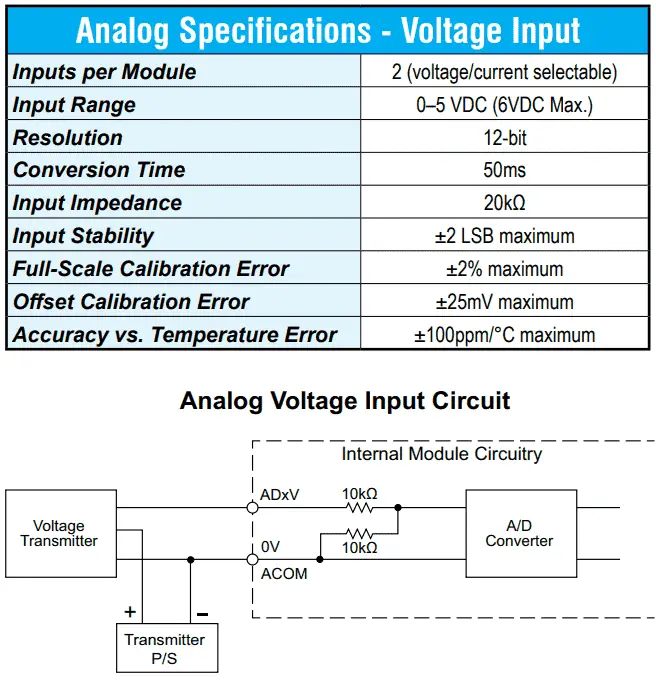 The input will accept voltage or current. This is selectable. The voltage range is 0 to 5 VDC. This must match the sensor that we are using for the tank. The response or conversion time is 50 milliseconds. This is the time required for the analog-to-digital converter to output the 12-bit resolution.
What is Meant by 12-Bit Resolution?
Resolution refers to the analog-to-digital converter. The number of bits specified is binary.
1111 1111 1111 binary = 4095 decimal
So the decimal number values range from 0 to 4095. The voltage input is 5 VDC, so the resolution is 5VDC / 4096. This is equal to 0.00122 VDC. Each of the 4096 steps is an increment of 0.00122 VDC.
Our analog input for the tank will measure 0 to 120 inches.
120 inches / 4096 = 0.02929 inches per step
The accuracy of our tank level signal conversion will be +/- 0.02929 inches for the measurement. You must also consider the accuracy of the sensor itself in any application.
You can use the windows calculator to help you with conversions between binary and decimal.
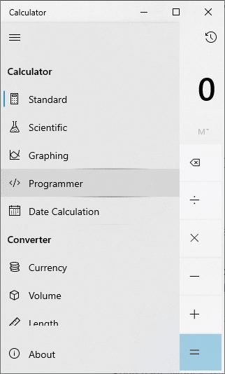 Select “Programmer” mode from the menu.
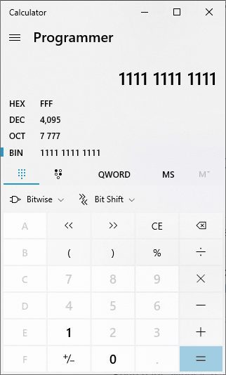 Select BIN (binary) for the numbering system. Enter 12 ones on the keyboard. The results will be shown in hexadecimal, decimal, and octal.
Click PLC Analog Setup
Call up the systems configuration window in the click programming software.
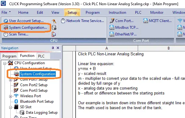 This can be selected under CPU configuration in the function tab in the navigation window. You can also set this under the main menu | Setup | System Configuration…
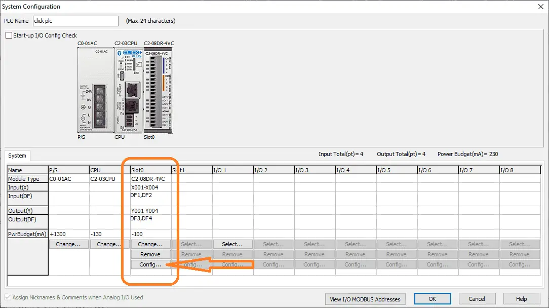 Select the config… button under slot 0 in the system configuration window.
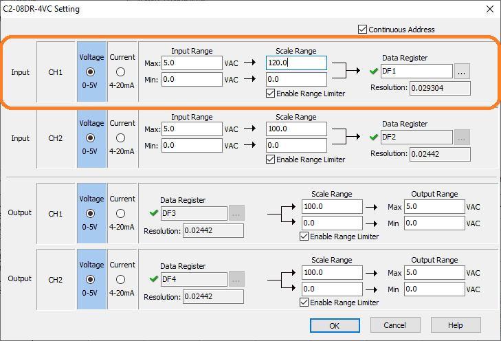 We will be wiring our analog input to the first channel. Our input is selected for voltages 0 to 5. The input range is 0.0 to 5.0.
110_png
The scaled values are 0.0 to 120.0 inches to represent our tank. Select OK to return to the system configuration. Select OK again to return to the programming window. Our analog setup and linear scaling are complete.
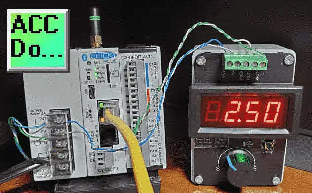
We will use an analog input simulator to generate the 0 to 5-volt DC signal.
Analog Linear Math Equation
We now have our analog input set up and scaled to give us the 0 to 120 inches for our tank level.
 We now must determine the volume of our tank.
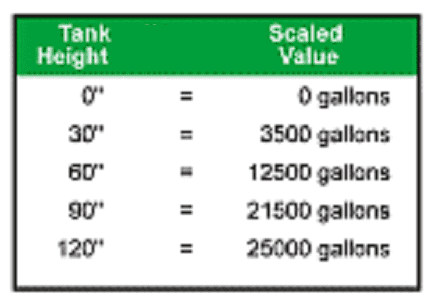 The volume based on the level is not linear.
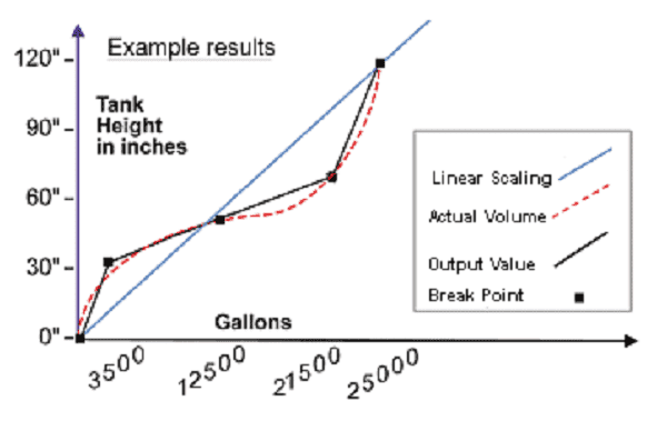 Looking at the above chart, we can approximate the volume using three separate linear lines.
Note The more lines you use, the better approximation of the volume.
The following formula can be used for scaling the linear line.
y = mx + b
Here are the following parameters:
y – This will be the scaled result.
m – This multiplier converts your data to the scaled value. It will be y’s full range divided by x’s full range.
x – This is the analog data you are converting.
b – This is the offset or difference between the starting points of x and y.
Depending on the level of the tank, we will use different math equations for the lines. We can now write our ladder logic PLC program for the Click.
Click PLC Ladder Logic Non-Linear Analog Program
The comparison will be used to determine the linear line segment we will use.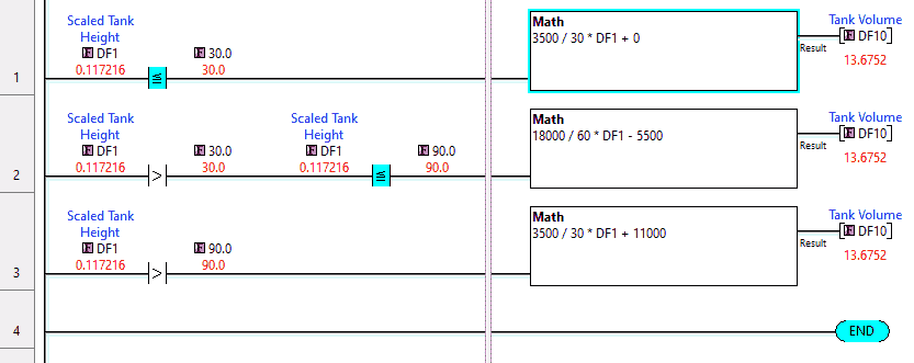 DF1 will be our linear scaled tank level from 0 to 120 inches. Based on this reading, different math instructions will be used depending on the linear line used.
Using the formula y=mx + b we can determine the linear line for the first segment from 0 to 30. We solve for the offset by selecting 30 as our reference point.
3500 = ((3500 – 0)/(30 – 0))*30 + b
b = 0 – This is because it intersects our axis.
Our formula for the first section is y = 3500/30 *x + 0
Moving our analog input to the midway point we will calculate the second linear line.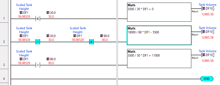
y=mx + b
12500 = ((21500 – 3500)/(90 – 30))*60 + b
b = -5500
Our formula for the first section is y = 18000/60 *x – 5500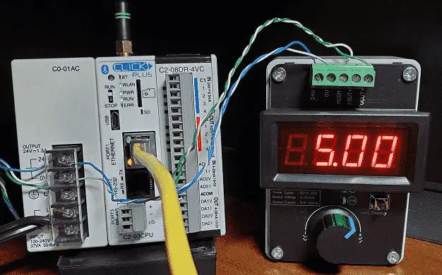
Moving the analog input to the maximum of 5 volts DC, we can calculate the last segment.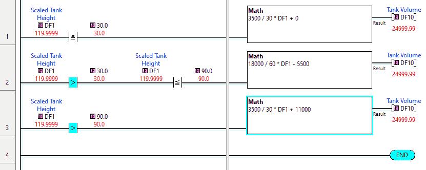
y=mx + b
25000 = ((25000 – 21500)/(120 – 90))*120 + b
b = 11000
Our formula for the first section is y = 3500/30 *x + 11000
Watch the video below to see the operation of our non-linear ladder logic program in the Click PLUS PLC.
Download the Click PLC non-linear ladder logic program here.
Click PLC Support Links
The Click PLC can be programmed using free Click programming software from Automation Direct. Here is a link to the software.
Version 3.31
Version 2.60
The entire Click PLC series can be found here. This includes the Click PLUS release.
All previous posts and information are still valid with the Click PLC line-up.
YouTube Click Playlist
YouTube Click PLUS Playlist
Click and Click PLUS PLC Overview
Click and Click PLUS PLC Videos from Automation Direct
Modbus Learning Links:
Simply Modbus Frequently Asked Questions
Modbus TCP/IP Overview – Real-Time Automation
All You Need to Know About Modbus RTU – Video
Watch on YouTube: Click PLC Analog Input Non-Linear Scaling
If you have any questions or need further information, please get in touch with me.
Thank you,
Garry
If you’re like most of my readers, you’re committed to learning about technology. Numbering systems used in PLCs are not challenging to learn and understand. We will walk through the numbering systems used in PLCs. This includes Bits, decimals, Hexadecimal, ASCII, and Floating points. To get this free article, subscribe to my free email newsletter.
Use the information to inform others how numbering systems work. Sign up now. The ‘Robust Data Logging for Free’ eBook is also available as a free download. The link is included when you subscribe to ACC Automation.