EasyPLC comes with many prebuilt machines for you to develop the programming logic. These can be modified, or new custom machines can be programmed using the machine editor. The machine editor comes as a standard feature of the EasyPLC Software Suite. The EasyPLC Machines Simulator editor is an easy-to-use tool enabling you to create easy, medium, or complex mechanical systems. These machine systems can include assembled mechanical, electrical, and electronic components.
If the components you need are unavailable in the library, you can use the components editor to create your mechanisms and devices. These machines help you to enhance your PLC programming skills. You can also replicate real, physical systems to be programmed virtually and avoid damaging the existing system. Alternatively, you can start programming and verifying your program before making the machine.
 EasyPLC comes with over 40 prebuilt machines. We will be using the Machine Simulator Editor to create a new machine mixing tank simulation. It will include a tank, control panel, and operation indication. Let’s get started.
Learn PLC programming the easy way. See below how to receive a 10% discount on this already cost-effective learning tool. Invest in yourself today.
Previously we have done the following:
Easy PLC Installing the Software – Video
EasyPLC Software Suite – Quick Start – Video
Click PLC – Easy Transfer Line Programming – Video
Productivity PLC Simulator – Chain Conveyor MS – Video
Do-More PLC – EasyPLC Box Selection Program – Video
Click PLC EasyPLC Gantry Simulator – Video
Click PLC Simple Conveyor EasyPLC – Video
EasyPLC Paint Line Bit Shift – BRX Do-More PLC – Video
Click PLC – EasyPLC PLC Mixer Programming – Video
Click PLC EasyPLC Warehouse Stacker Example – Video
– Operation Video
EasyPLC Machine Simulator Productivity PLC Robotic Cell – Video
EasyPLC Simulator Robotic Cell Click PLC – Video
EasyPLC Simulator Robotic Cell BRX Do-More PLC – Video
– EasyPLC Factory Editor Robotic Cell Additions Video
4 Way Traffic Light PLC Program EasyPLC – Video
Rock Crusher Plant EasyPLC BRX Do-More – Video
Freight Carrier Weighing and Distribution EasyPLC – Video
EasyPLC Machining Center Loading Robots – Video
EasyPLC Palletizing Robot Programming Click PLC – Video
EasyPLC Machine Simulator Editor Start
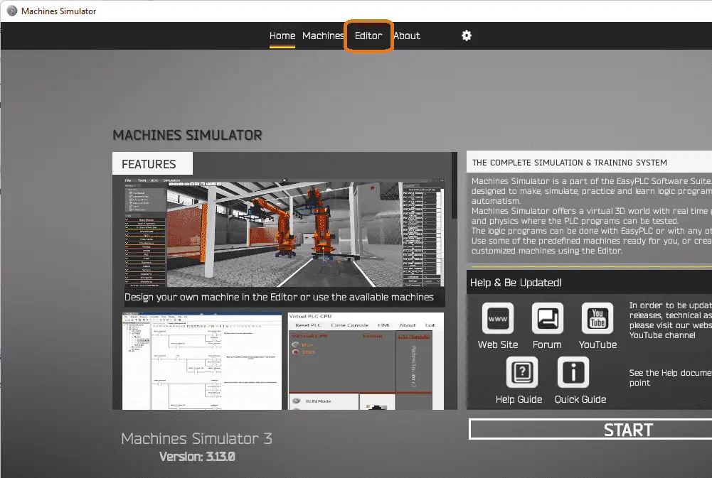
The Easy PLC Machines Simulator offers a virtual 3D world with real-time graphics and physical properties where you can test the PLC programs. You can create your machines or use some of the different predefined machines. Start the Machine Simulator software.
 Select the options icon on the main menu. This will be used to set up the options for the machine simulator and editor.
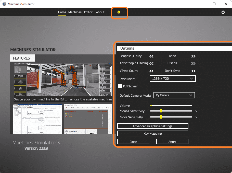 Resolution and volume are just a couple of the items that you may want to change based on your current system.
Select Editor from the main menu. This machine simulator window will present you with three different backgrounds.
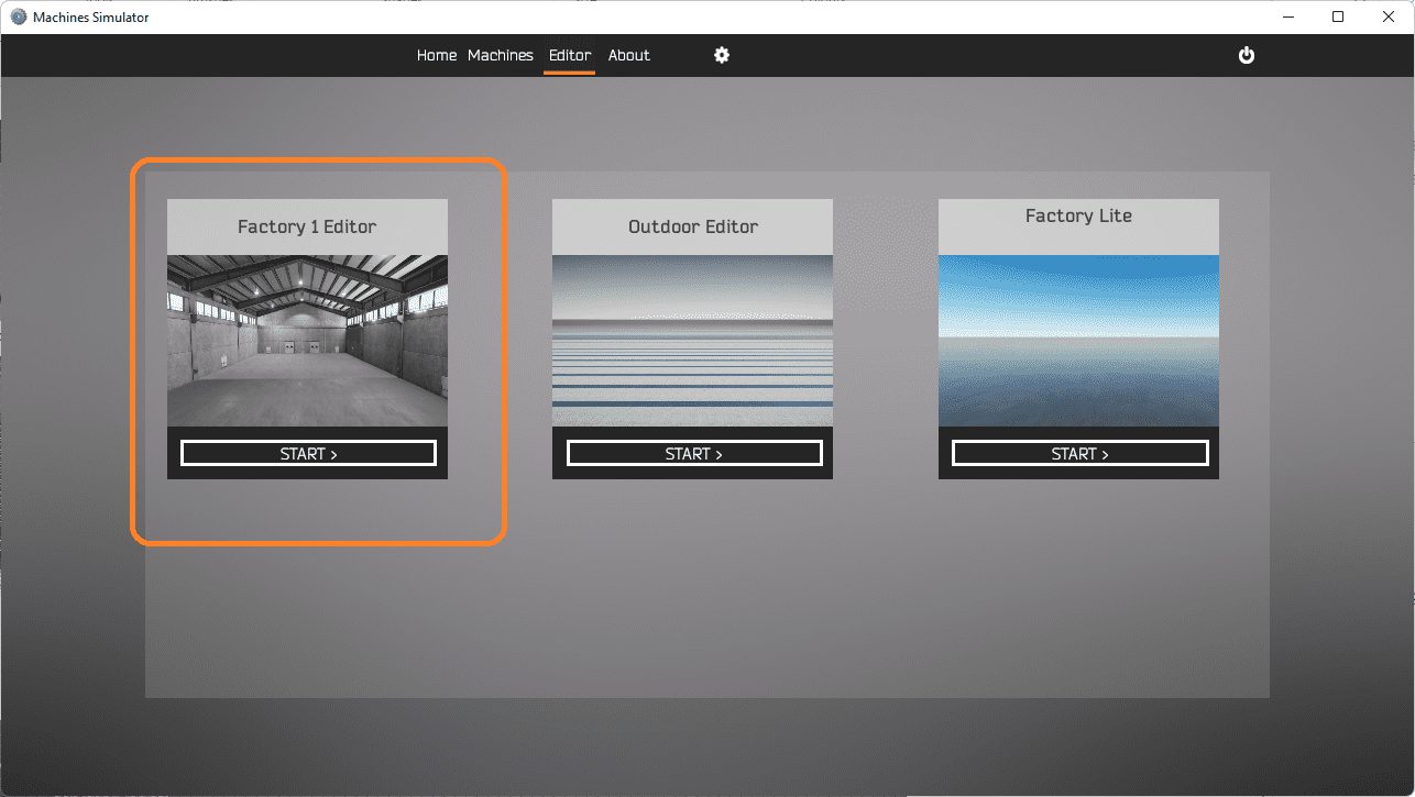 The machine editor, as previously mentioned, will modify the existing prebuilt machines, or you can start a new machine. Select the Factory 1 Editor.
Machines Simulator Editor Menus
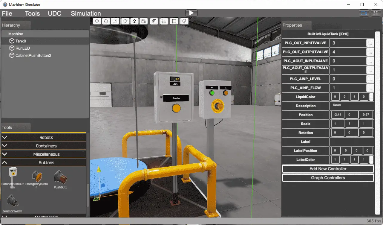
The machine simulator window for the editor has an excellent graphical user interface. The editor menus consist of the main menu across the top of the screen. It includes the File, Tools, UDC, and Simulation selections. This will allow you to work with the entire machine.
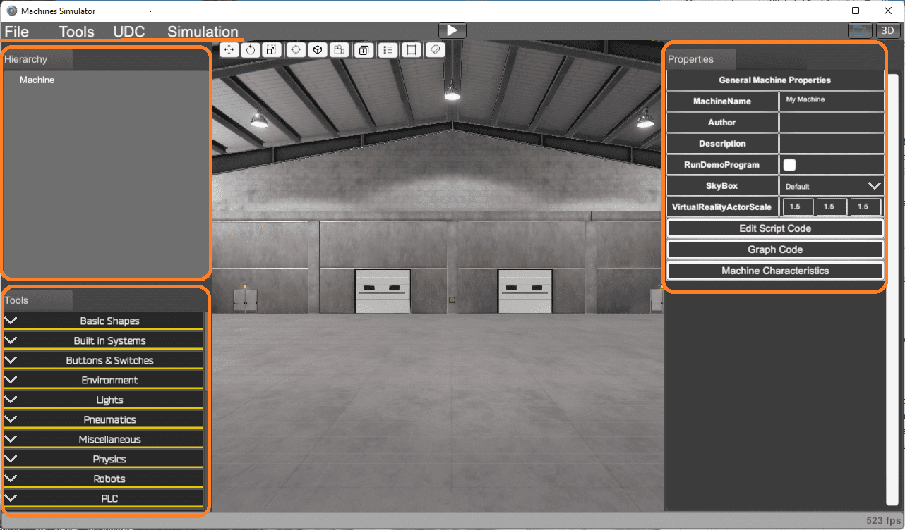 The remaining screen is broken down into four areas.
The center of the screen will show the current machine and background settings. This will represent how and where the machine will be displayed.
The hierarchy will show you all the components displayed in the center of the screen. It is in the top left of the screen. This is a list of the items that can be selected and properties changed.
Tools will allow you to select items in the editor library to add to the hierarchy. This is where you will choose the machine and components to use on your custom machine.
Characteristics and functionality can be selected for each of the components. The properties menu will be displayed once an element is selected. This will appear on the right of the screen. A click can choose the item from it in the center area, a selection from the hierarchy, or a tools area.
Add Built-in Systems and Components
Select the necessary components from the Machines Simulator editor library to build your machine. In the editor library, you will find different sensors and actuators, such as photocells, inductive switches, electric motors, transporter trays, and elevators.
We will add the liquid tank from the built-in systems under the tools in our example. 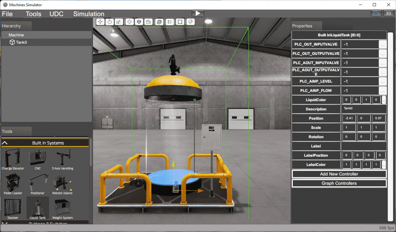 Once the tank has been selected, you can move your mouse around the viewing window to position it. Clicking on the viewing window will set the tank position. You will see three arrows on the tank with a green outline indicating the selected object. Click hold and drag the arrows to place the tank finely.
Note: Use the scroll key on your mouse to zoom in and out. You can change the camera angle by pressing down on the scroll key and moving the mouse.
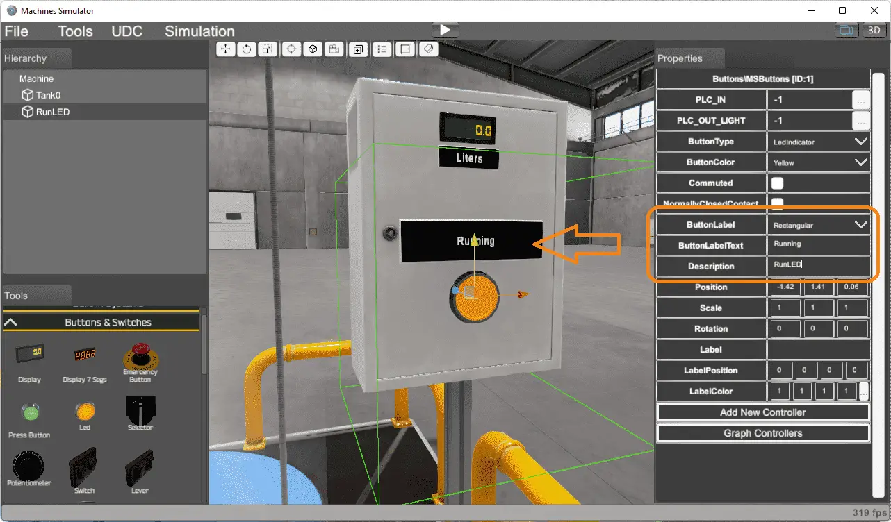 Select the LED under the buttons and switches in the tools window. Using the three arrows, position the button on the tank’s control panel. This light will be used to indicate that the mixing tank is running.
Add a rectangular button label and label it “Running.” The description will be set for “RunLED.” This is the name of the LED through the digital inputs and outputs.
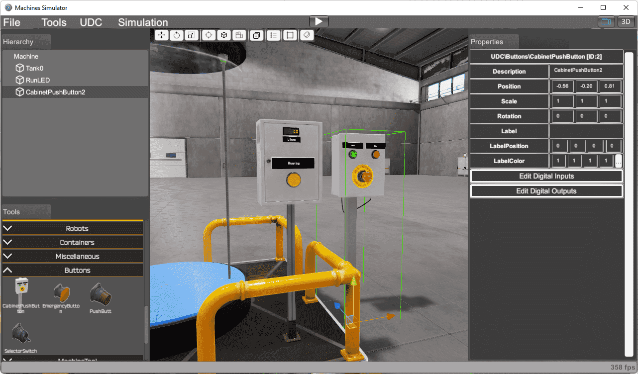 Add a cabinet pushbutton station under the buttons on the tools window. Position it next to the tank control station.
Watch the video below showing how to add and move components on the tool window to your machine.
Assign Addresses
The EasyPLC machine editor allows you to easily configure the input/output assignments with specific element characteristics. Select the cabinet push button on the hierarchy window.
 Select the edit digital inputs from the properties window. Select the three dots next to the start button input. The digital inputs window will appear on the lower right-hand side of the screen.
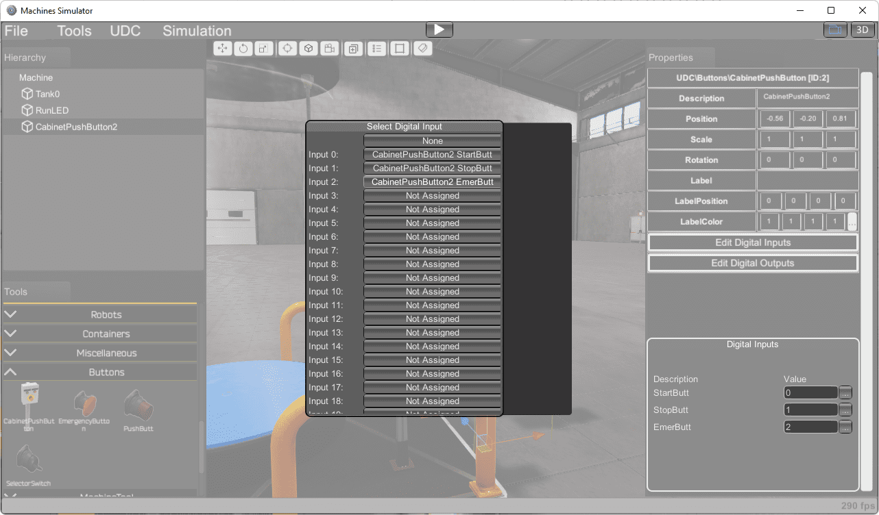 Select the input 0 for the start button. Continue until all of the inputs have been selected.
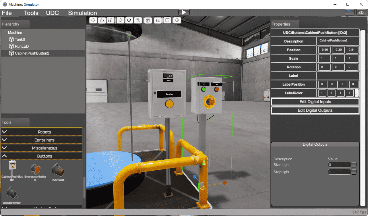 Select the digital outputs and assign them the outputs starting at 0.
In the hierarchy window, select the RunLED object.
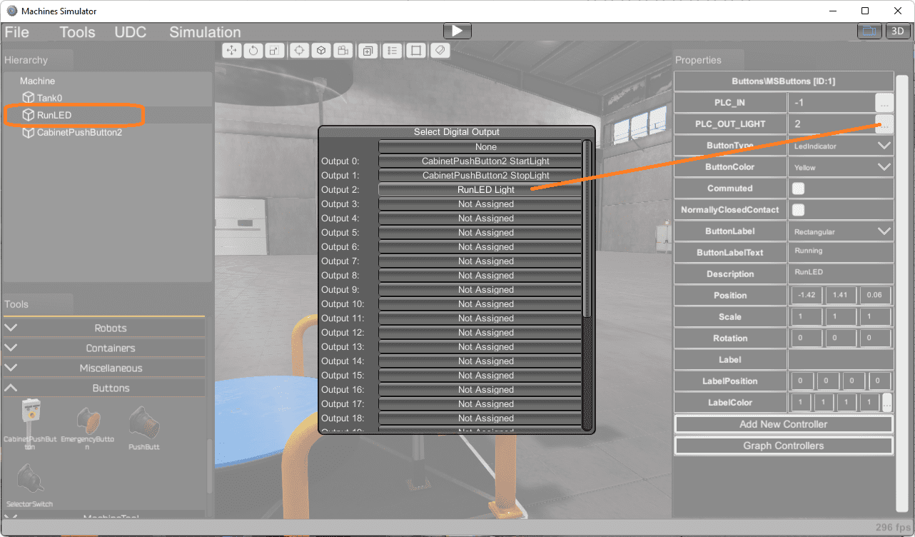 Assign output 2 to the PLC output light.
Continue assigning the inputs and outputs to the tank.
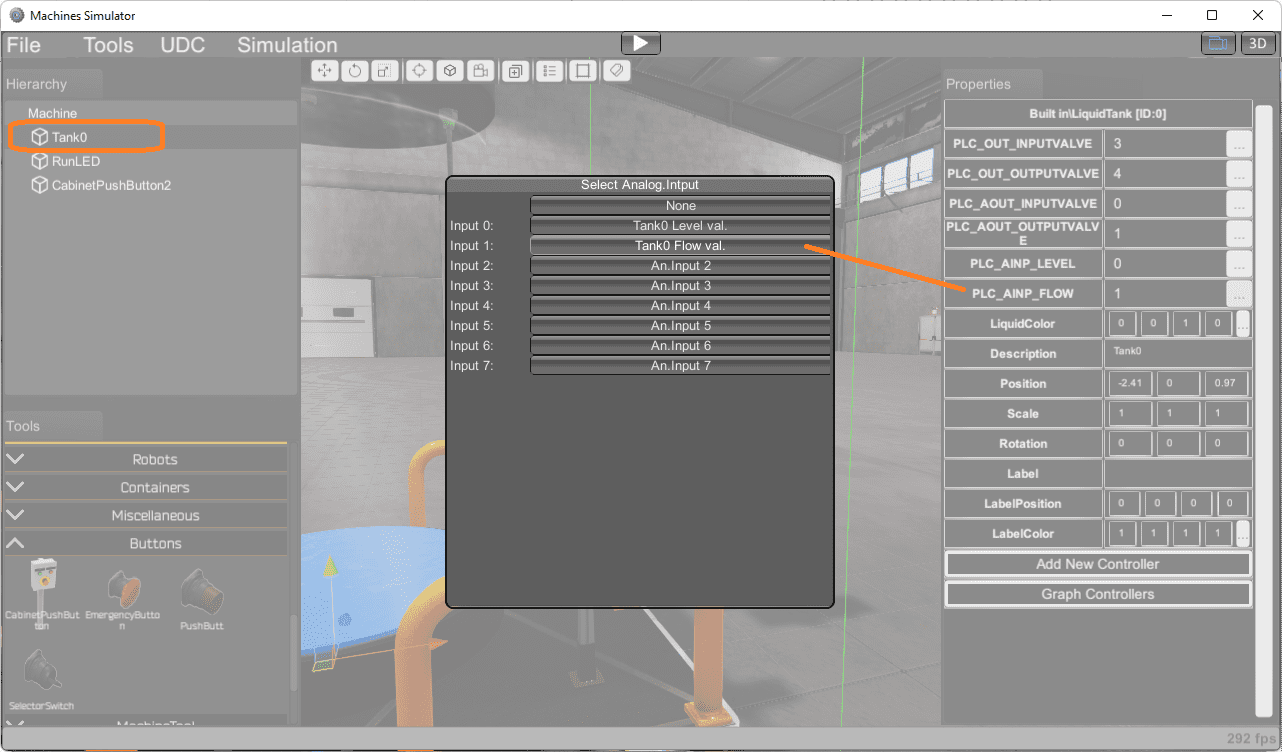 The tank will also have analog inputs and outputs.
 Watch the video below to see how easily the addresses are assigned to our mixing tank.
Running / Testing the New Machine Simulator
We can now run our new mixing machine simulator.
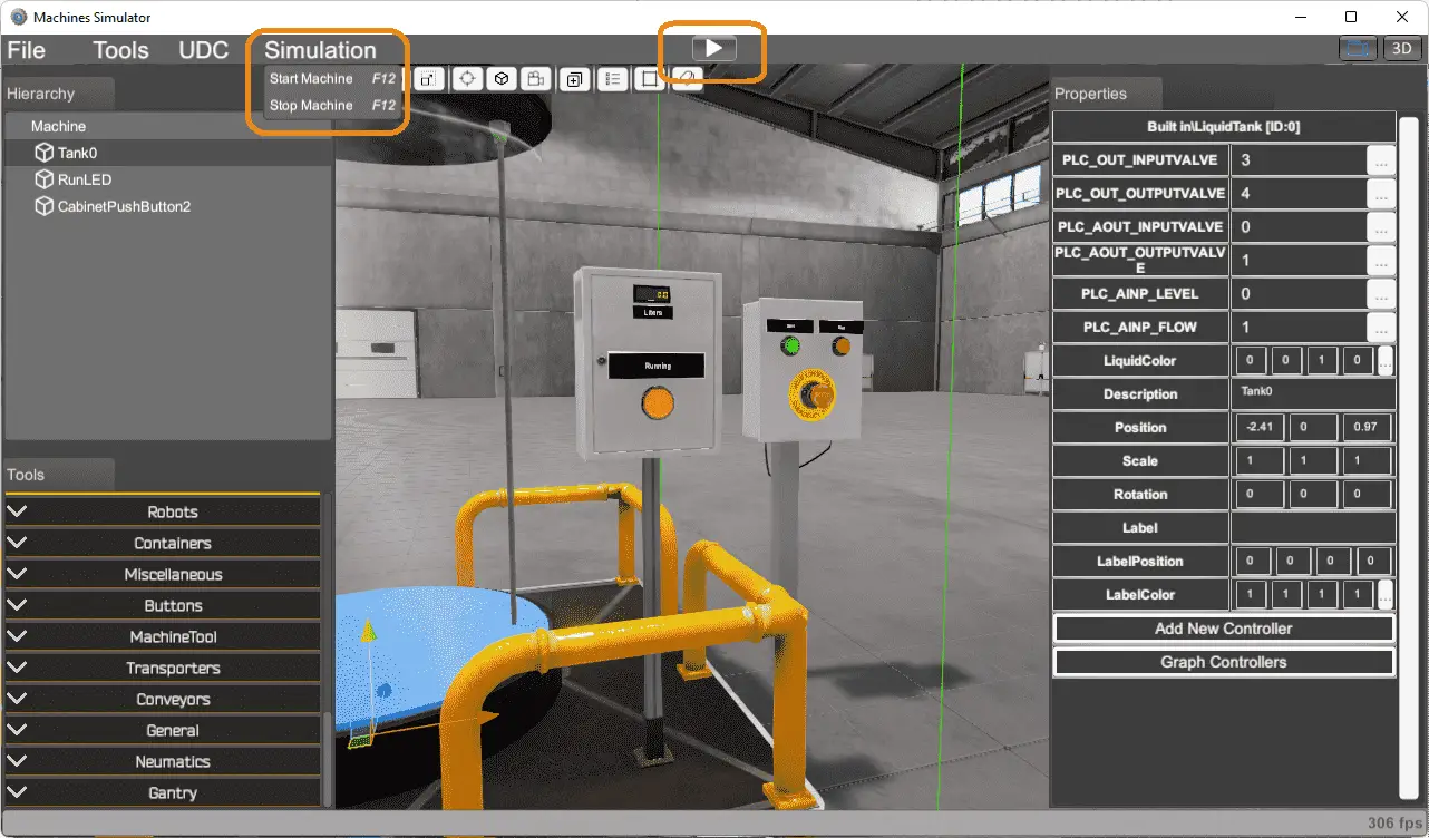 Select start machine under simulation on the main menu or select the play button icon on the main menu.
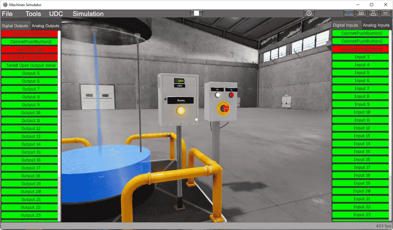 We can manually turn on the digital or analog outputs and monitor the digital or analog inputs.
Note: For this to function automatically, you must connect to a PLC or controller.
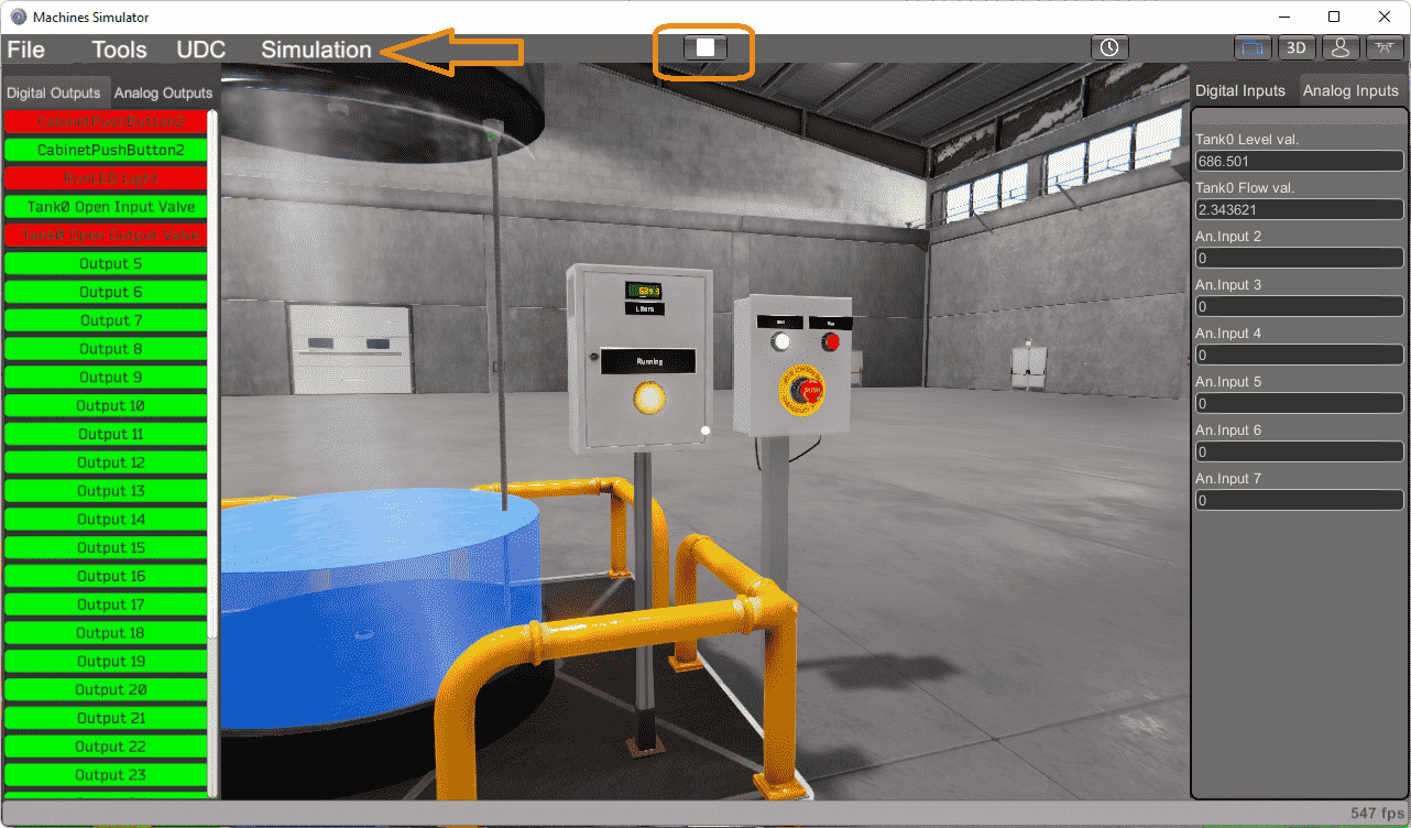 Stopping the machine can be done by selecting it under simulation on the main menu. You can also use the stop icon on the main menu.
Now that we have seen that our machine will run, it is time to save and document.
Saving the Machine
The first thing to do is to name this machine.
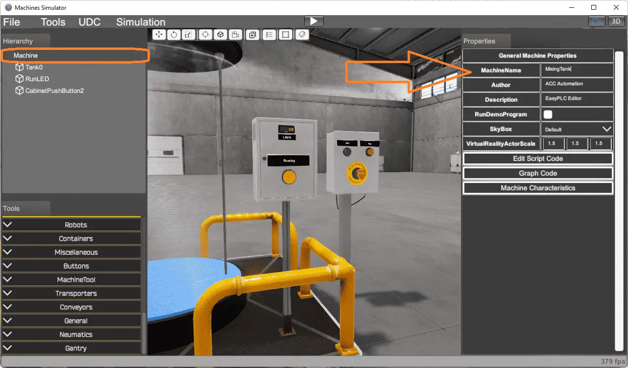 Select the machine on the hierarchy window. In the properties window, call the machine name mixing tank. We have also filled in the author and description.
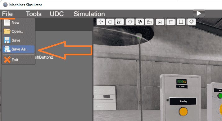
On the main menu, select file, save as.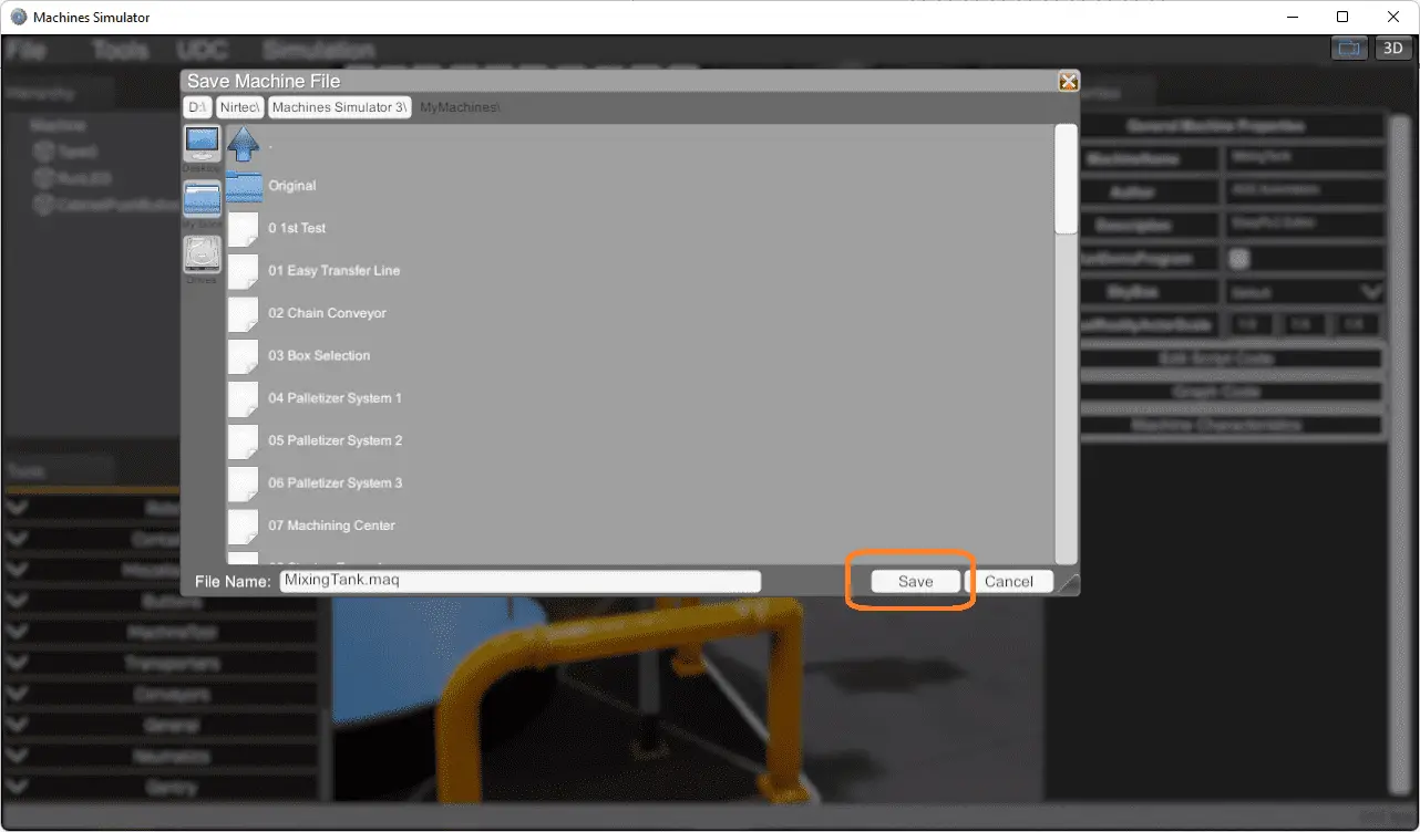
The file name will be the machine name “MixingTank.” We can change this if we want, but I would keep it the same. Make a note of the location of the file. It will default to the location for all of the prebuilt machines. Select Save.
A picture can be assigned to this machine. To make a picture, run the device once again.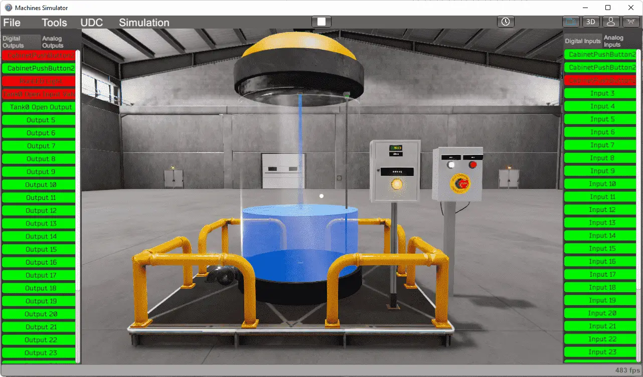
Alt + PrtScrn will copy the current window to the clipboard on your Windows PC.
Note: Ctrl + PrtScren will copy the entire screen to the clipboard.
Call up the windows Paint program.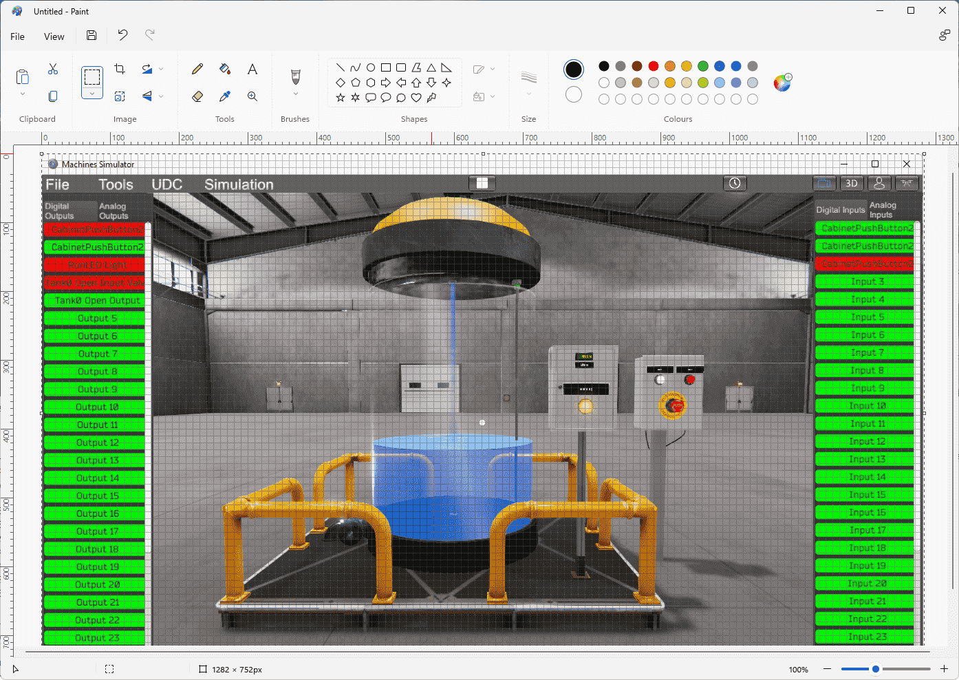
Using the shortcut for paste (Ctrl + v), we can copy the clipboard into the paint program. 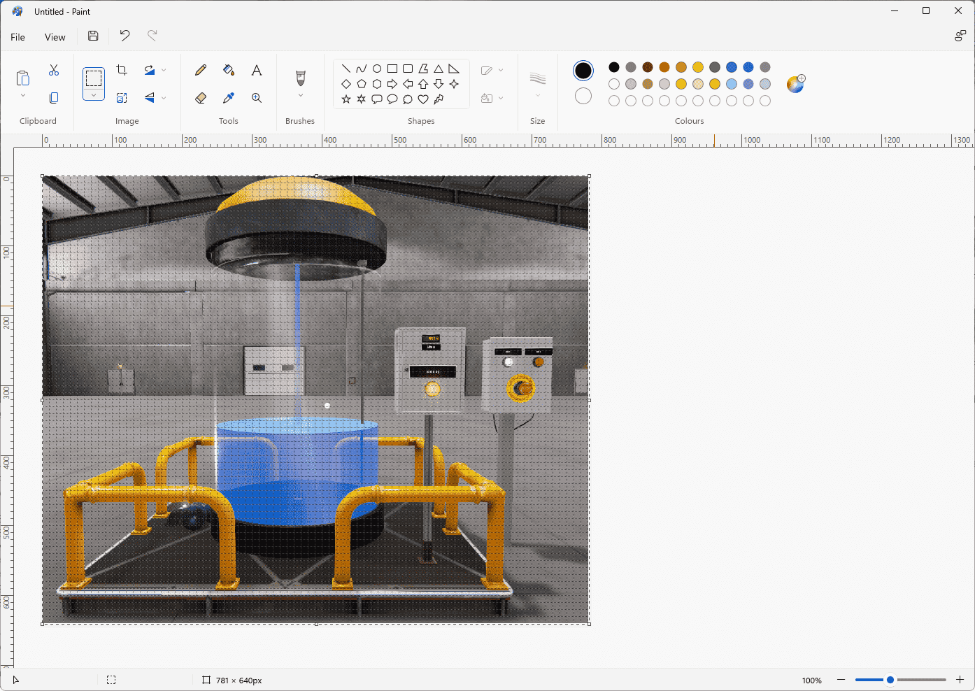
Using the selection tool in paint, we can highlight and copy the area we want for our picture. (Ctrl + c) Start a new paint picture and paste this from the clipboard. 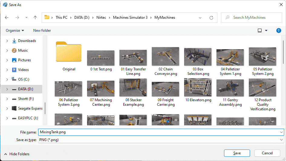
Save the picture as MixingTank.png in the same directory as our mixing tank simulator program. 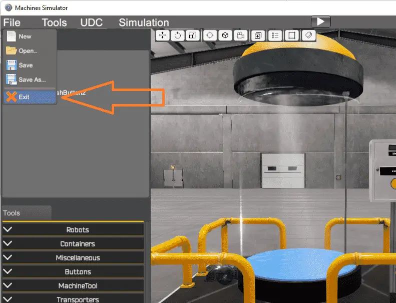
Exit the machine simulator editor using the main menu, file, and exit. 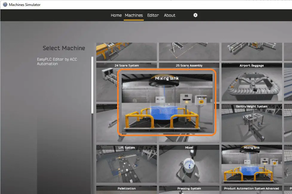
Calling our machines in the machine simulator will now give us an option to use our mixing tank.
Download the EasyPLC MixingTank sample program created above here.
Watch the video below to see the development of our mixing tank using the EasyPLC machine editor. The machine simulator is one of the best applications to help you learn PLC programming.
EasyPLC Software Suite is a complete PLC, HMI, and Machine Simulator package. This PLC learning package includes the following:
Easy PLC – PLC Simulation allows programming in Ladder, Grafcet, Logic Blocks, or Script.
HMI System – Easily create a visual human-machine interface (HMI)
Machine Simulator – A virtual 3D world with real-time graphics and physical properties. PLC programs can be tested using EasyPLC or through other interfaces. (Modbus RTU, TCP, etc.)
Machine Simulator Lite – Designed to run on Android Devices.
Machine Simulator VR – Virtual Reality comes to life so you can test, train or practice your PLC programming.
Purchase your copy of this learning package for less than USD 75 for a single computer install or less than USD 100 to allow different computers.
Receive 10% off the price by typing in ACC in the comment section when you order. http://www.nirtec.com/index.php/purchase-price/
Learn PLC programming the easy way. Invest in yourself today.
Watch on YouTube: EasyPLC Machine Editor – Design a Simulation
If you have any questions or need further information, please contact me.
Thank you,
Garry
If you’re like most of my readers, you’re committed to learning about technology. Numbering systems used in PLCs are not challenging to learn and understand. We will walk through the numbering systems used in PLCs. This includes Bits, decimals, Hexadecimal, ASCII, and Floating points.
To get this free article, subscribe to my free email newsletter.
Use the information to inform other people how numbering systems work. Sign up now.

The ‘Robust Data Logging for Free’ eBook is also available for free download. The link is included when you subscribe to ACC Automation.