So far in this series, we have discussed the Click PLC System Hardware (Video) and Installed the Software (Video). Today we will be establishing PC to PLC communications. This will allow us to program, edit or alter the way in which our Click PLC will function.
Start the Click Programming Software. This can be done from the windows start menu.
Start Menu | All Programs | AutomationDirect | CLICK Ver2.00 | CLICK Programming Software Ver2.00
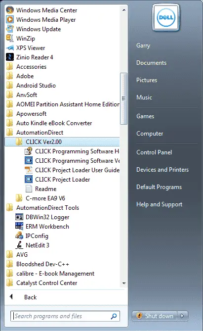
You can also start the software by the icon on the desktop or the icon in the quick start menu.

When the program starts, a splash screen is presented and then the ‘Startup’ window will open. You have one of three choices to make. Start a new project, open an existing project or Connect to PLC.
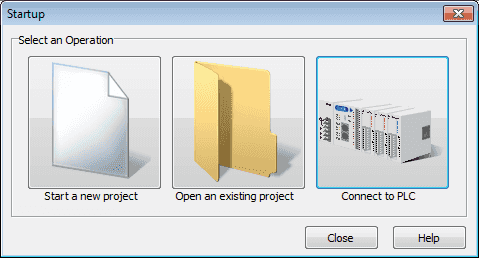
Select the ‘Connect to PLC’. We want to be sure that we can communicate with the controller before creating a program.
USB to RS232 Click Communication
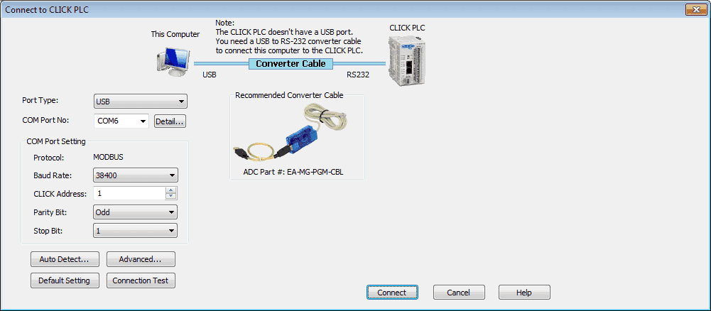
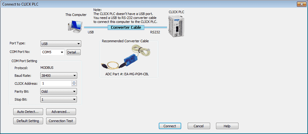
The first method that we will use to communicate to the controller is through the USB port. In our case, we have the USB to RS232 converter cable. This ‘Connect to CLICK PLC’ window consists of the following:
Port Type: USB – This is the communication port type to connect to the Click PLC
COM Port No: This is the communication port number that has been assigned to the USB device. To see a list of all available port numbers on the computer click the Detail button.
COM Port Setting: The communication port settings must match the settings in the PLC. Default settings for the PLC and software for RS232 are as follows:
- Protocol: Modbus – This is the method to program the Click PLC
- Baud Rate: 38400 bits per second communication rate
- Address: 1 – If we had several Click PLCs on the same network, we could then assign an address to each one. Note: RS485 would be the serial type that would be appropriate for 1:N communication. RS232 is mainly for 1:1 communication.
- Parity Bit: Odd – Parity is used to ensure that the information sent from one end is the same as the other. It is a check to ensure the message is valid and we didn’t loose any bits along the way.
- Stop Bit: 1 – The stop bit gives a period of time before the next start bit can be transmitted.
Auto Detect: This will open the automatic detection dialog box. Each possible combination of the above will be tried to see if a connection to the PLC can be done.
Advanced: We can use the advanced settings for the port to set the Timeout Time and Retry time of the port.
Default Setting: We can return to the Click PLC default port settings by using this button.
Connection Test: This will test the currently selected settings and give you a popup window if communication can be established or not.
Once we have the settings select ‘Connect’ to communicate to the PLC. We will be presented with two options.
Read the project from the PLC (You will have a chance to save the project currently opened in the software after this.)
Don’t read the project from the PLC (This software will be connected to the PLC, but the project currently opened in the software will remain.)
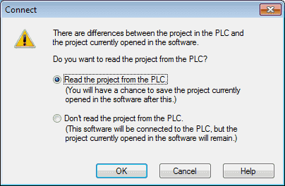
Select ‘Read the project from the PLC’. We currently do not have a project started.
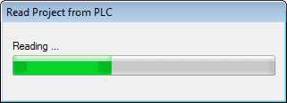
Communication will now start and the program in the PLC will be uploaded into the software.

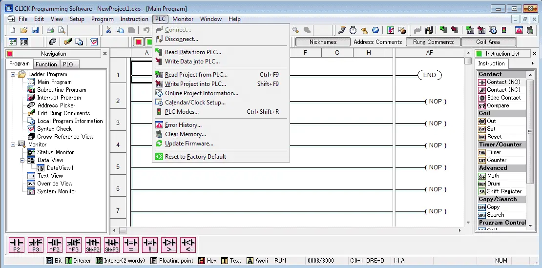
We can tell that we are communicating by the following on the main screen of the Click programming software.

- Online will be displayed instead of Offline
- RUN or STOP will be displayed for the PLC Mode instead of it being greyed out.
- PLC Error is normally greyed out. When connected online this will show PLC errors or indicate ‘No PLC Error’.
Disconnecting from the PLC can be done in several ways. We can click the ‘Online’ button, Disconnect Icon or select the PLC menu and select Disconnect.
You will be prompted if you really want to disconnect from the PLC. Select Yes to stop communications.
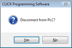
Note: Always disconnect from the PLC before removing or unplugging communication cables.
USB to RS485 Click Communication
The second method to communicate to the Click PLC will be using a USB to RS485 adapter. We will communicate to Port3 on the PLC. Installing the driver for this adapter must be done prior to trying to communicate to the PLC. Installation of the adapter can be found at the following URL location:
https://accautomation.ca/usb-to-rs485-pc-adapter-installation/
Communication will be the same as using the USB to RS232 adapter. The only difference will be the communication port that you use on your computer. RS485 is a 1:N serial communication system. This would be ideal for multiple devices on the same network.
Our last method is the quickest method that we can communicate to the Click PLC. Ethernet communications will be used usually in connection with a Switch/Hub.
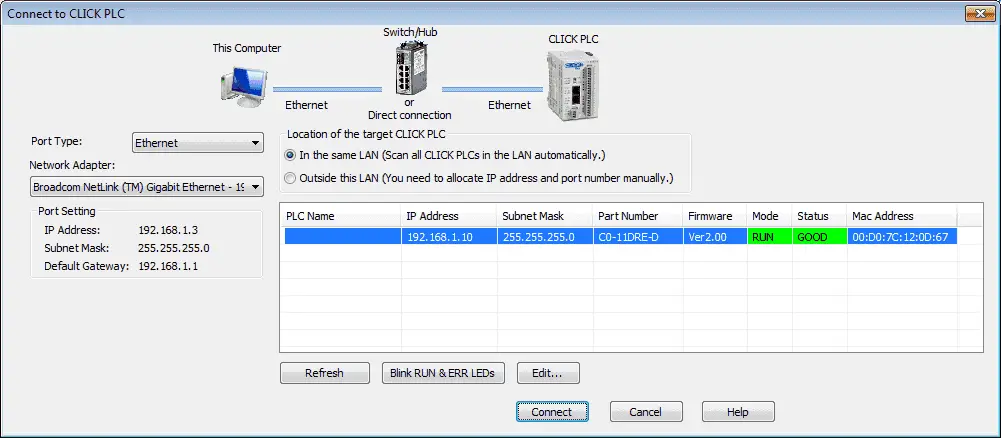
The Connect to CLICK PLC window consists of the following:
Port Type: – Ethernet (RJ45)
Network Adapter: – These are the network adapters that are part of your computer system. This will also work with a wireless network adapter.
Location of the target CLICK PLC: – Inside the same local area network (LAN) or outside the LAN.
List of Click PLCs: – A list of all of the Click PLCs will be displayed in the table. This will show all of the information about the PLC so we can then communicate to it.
Refresh: – This will scan the LAN again and determine the Click PLCs that are connected.
Blink RUN & ERR LEDs: This will turn alternate the RUN and ERR LED on and off for the selected Click PLC. This will help assist you to determine if you are communicating to the correct PLC.
Edit… : This will open the edit window so you can change the IP Address, Subnet Mask and Default Gateway of the Ethernet port on the Click PLC.
Here is some additional information on what everybody ought to know about IP addressing.
https://accautomation.ca/what-everybody-ought-to-know-about-ip-addressing/
Once you have everything set. Hit the connect button. This will then be the same as our communication above.
Next time we will look at the Click PLC numbering systems and addressing.
Watch on YouTube: Click PLC Establish Communication
If you have any questions or need further information please contact me.
Thank you,
Garry
If you’re like most of my readers, you’re committed to learning about technology. Numbering systems used in PLC’s are not difficult to learn and understand. We will walk through the numbering systems used in PLCs. This includes Bits, Decimal, Hexadecimal, ASCII and Floating Point.
To get this free article, subscribe to my free email newsletter.
Use the information to inform other people how numbering systems work. Sign up now.

The ‘Robust Data Logging for Free’ eBook is also available as a free download. The link is included when you subscribe to ACC Automation.