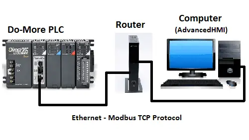
We will now create a PLC with HMI Training and learning environment. We will use the Automation Direct Do-More programming software tied into the Advanced HMI learning package via Modbus TCP. All of the software is free and fully functional. Learn PLC programming and use a powerful HMI (Human Machine Interface) easily and freely.
Setting up our PLC and HMI Learning environment
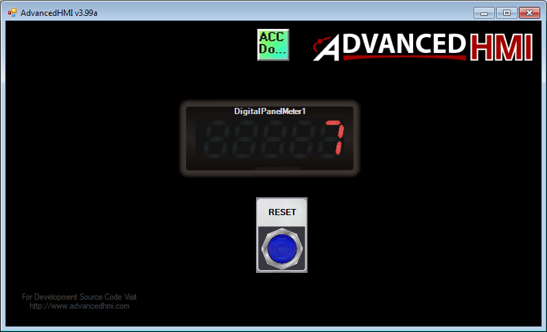
Our learning application will show an HMI screen with a panel meter and a reset button. The panel meter value may be changed by clicking it. This will bring up an input screen to put in a number. When the reset button is selected, the input value entered will show on the panel meter.
Modbus TCP Addresses – Communication between HMI and PLC
Since we will communicate via Modbus TCP, the following table shows the Coil/Register Numbers and the associated Do-More PLC Addresses.
| Coil/Register Numbers | Data Addresses | Type | Do-More PLC | Table Name |
| 00001-09999 | 0000 to 270E | Read-Write | MC1 to MC1023 | Discrete Output Coils |
| 10001-19999 | 0000 to 270E | Read-Only | MI1 to MI1023 | Discrete Input Contacts |
| 30001-39999 | 0000 to 270E | Read-Only | MIR1 to MIR2047 | Analog Input Registers |
| 40001-49999 | 0000 to 270E | Read-Write | MHR1 to MHR2047 | Analog Output Holding Registers |
Note: The Do More PLC uses the Modbus area to communicate. Data must move in and out of this area via the PLC program. This is because having direct access to the digital I/O can be dangerous when connected via Ethernet to the internet.
PLC Learning – Do-More Designer Download
We will first start with the PLC learning software.
Automation Direct has a powerful simulator with their Do-More PLC. It is the Do-More Designer Software. This software simulator includes the instruction set (Not Just a Bit of Logic) and communication protocols. It can be downloaded and installed for free from the above link.
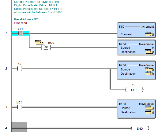
Our PLC learning program will have the following addresses:
Digital Panel Meter Present Value (PV) – MHR1 – Modbus 40001
Digital Panel Meter Set Value (SV) – MHR2 – Modbus 40002
Reset Button – MC1 – Modbus 00001
The first rung of the ladder will use the 1-second pulse bit and increment the PV value of our digital panel meter. This will also compare the current value to 4000, and if greater or equal, move the value of zero into the PV value.
The ladder’s second rung will move WX0 analog value from our simulator into the PV value of our digital panel meter.
The ladder’s last rung will move the SV value into the PV value of our Digital Panel Meter. This happens when the reset is hit.
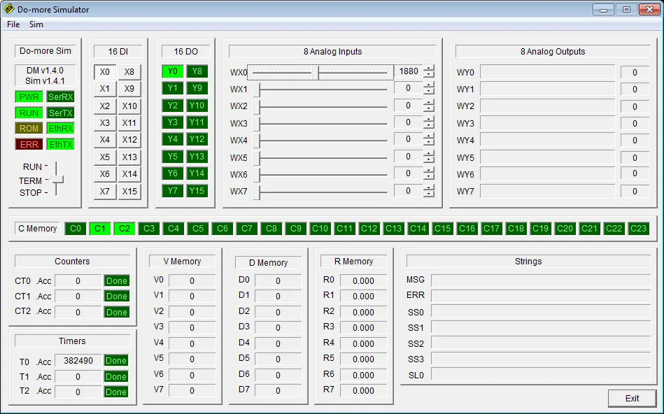
The simulator shows X0, and we can then use the WX0 slider to change the PV value of the Panel Meter.
HMI Learning – AdvancedHMI Visual Studio Download
Advanced HMI is a powerful HMI/SCADA (Supervisory Control and Data Acquisition) development package that uses Visual Studio. No coding is required; you can drag and drop items onto the page. The best thing is that the software is free for our learning environment.
Communications drivers include the following and are accessible via VB or C# code:
- Allen Bradley DF1 RS232 Driver
- Allen Bradley Ethernet/IP Driver for SLC, MicroLogix, ControlLogix, and CompactLogix
- Beckhoff TwinCAT Driver
- Modbus TCP Driver
- Modbus RTU Driver
- Omron Ethernet FINS Driver – Ethernet for newer controllers such as CP1H with Ethernet module
- Omron Serial FINS Driver – Serial (RS232 / RS485) for newer controller such as CP1H
- Omron Serial HostLink Driver – Serial (RS232 / RS485) for controllers such as CQM1, C200H, K-Series (C28K), C200, etc
The power of Advanced HMI is that it works within Visual Studio. You can use this program-integrated development environment (IDE) to modify or create new features, including data-logging applications.
Advanced HMI runs on Visual Studio 2008 or higher and must be installed on your PC. Visual Studio Community Edition 2015 is the latest version of the software. If you do not have it installed, please download and install it from the following link.
https://www.visualstudio.com/en-us/products/visual-studio-community-vs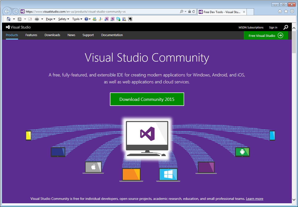
We will now need the Advanced HMI project. Here is the link to download the zip file.
http://sourceforge.net/projects/advancedhmi/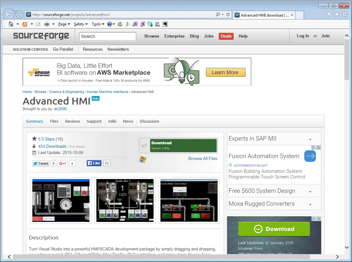
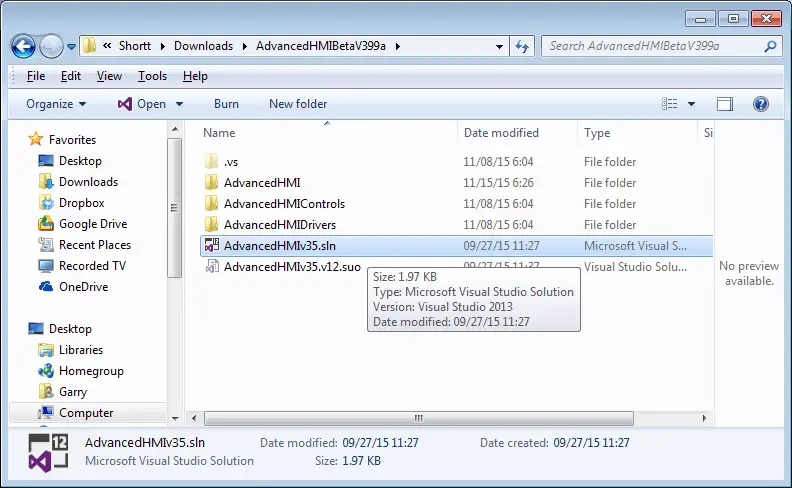
After downloading ‘AdvancedHMIBetaV399a.zip,’ extract the files from the zip file. (Right Click. Select Extract All)
Note: Your version might be different than the one above.
Open the solution file (AdvancedHMIv35.sln) from the extracted files in the root directory.
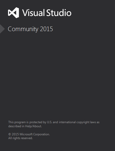
Our initial screen looks like the following. The project must now be compiled to add the components to the Toolbox.
Select Build | Build Solution from the menu
The next thing to do is add communication to the form. You will see the’ Toolbox’ on the left-hand side of the screen. Click on it, and under AdvancedHMIDrivers Components, we will select ModbusTCPCom. To add a component to our form, you need to drag it. Select the component, and move to the form as you hold the mouse button down.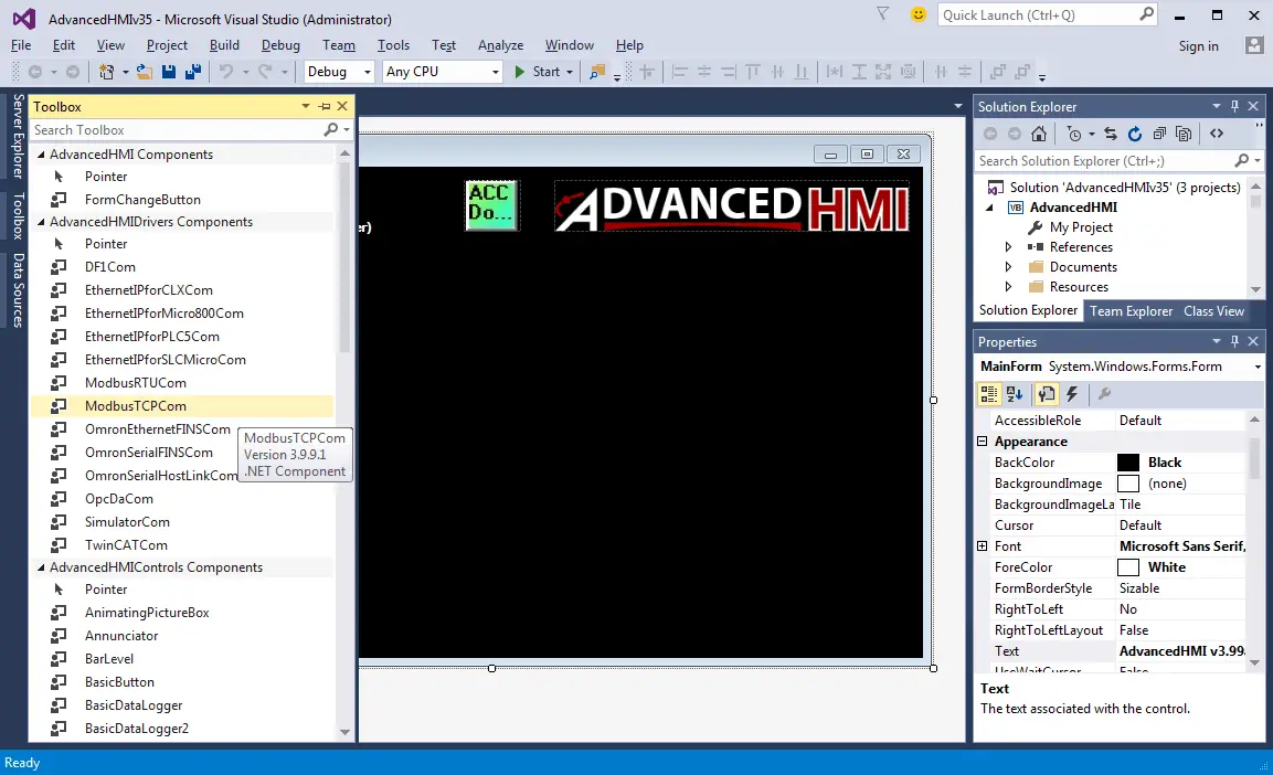
After adding the ModbusTCPCom component, it will appear at the bottom, beneath our form.
Click on ModbusTCPCom1 at the bottom of our form. On the right-hand side, you will notice the properties of this communication driver. Under Communication Settings | IP Address, enter the IP address’s value for the PLC. (192.168.1.3). Ensure that the port number is 502. This is the default port number for Modbus TCP.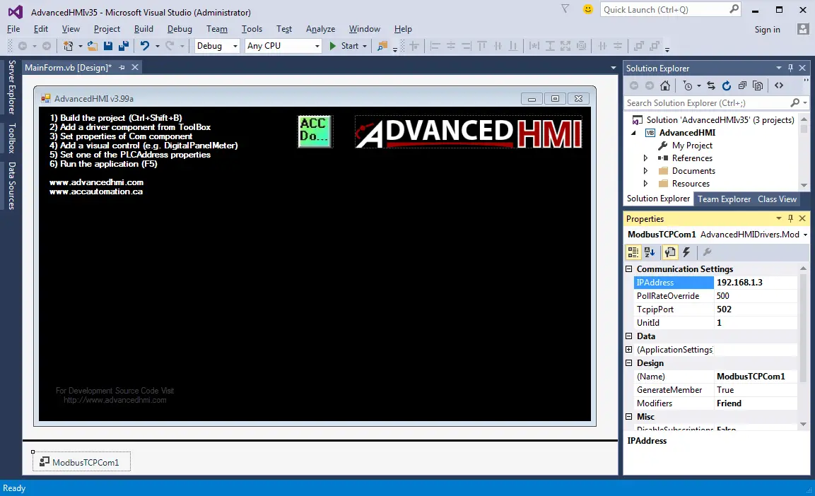
We can now add the digital panel meter. From the Toolbox, select and drag the DigitalPanelMeter to our form.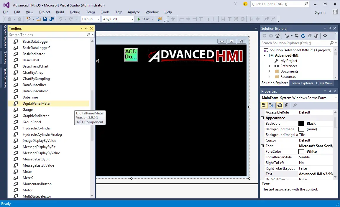
Resize the panel meter on the form by dragging a corner of the component.
While the panel meter is clicked, set the Properties | PLC Properties of the component:
PLCAddressValue – 40001 – MHR1 – Value to display on the meter.
PLCAddressKeypad – 40002 – MHR2 – This is the location of the stored number when the operator selects the meter and enters a number in the keypad.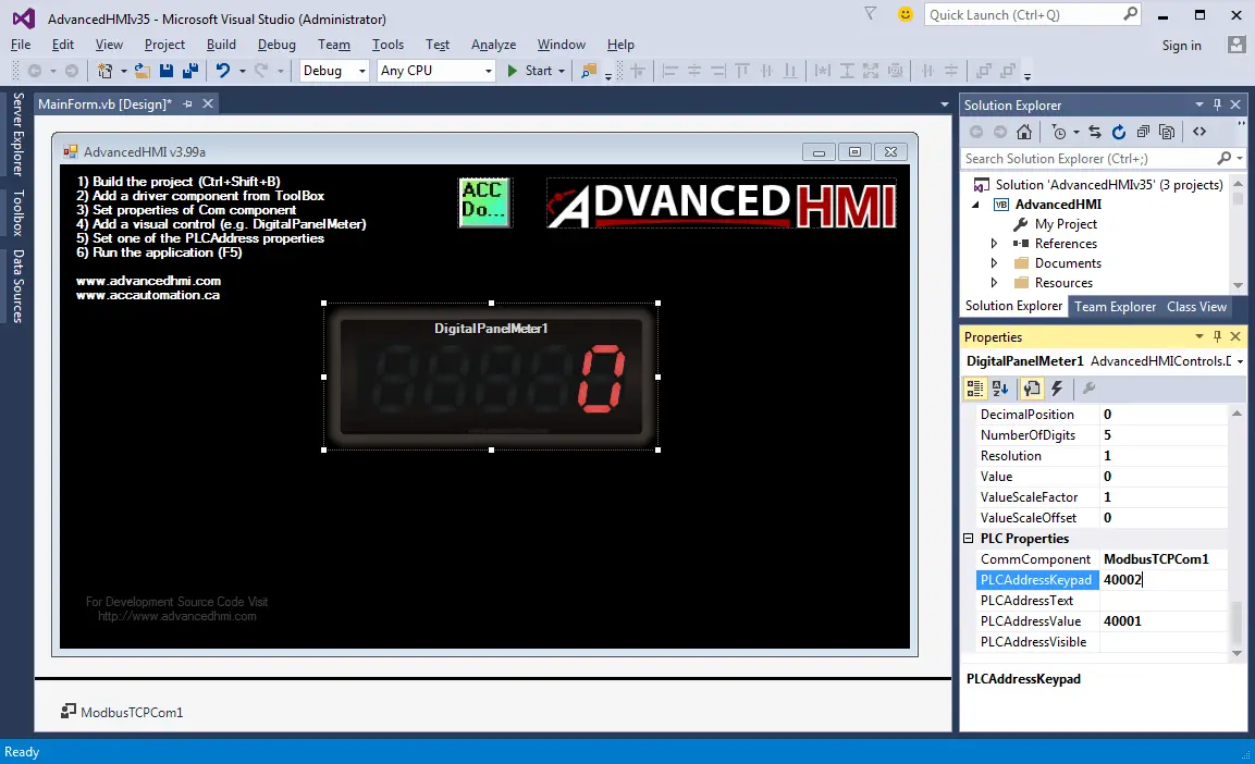
Add a MomentaryButton to our form by selecting and dragging it from the Toolbox.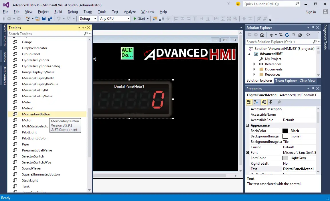
After resizing the component, we can change the color to blue under Properties | Misc. Also, change the text on the button to ‘RESET.’
Set the PLCAddressClick value to 00001. This is addressed in MC1 in the Do-More PLC.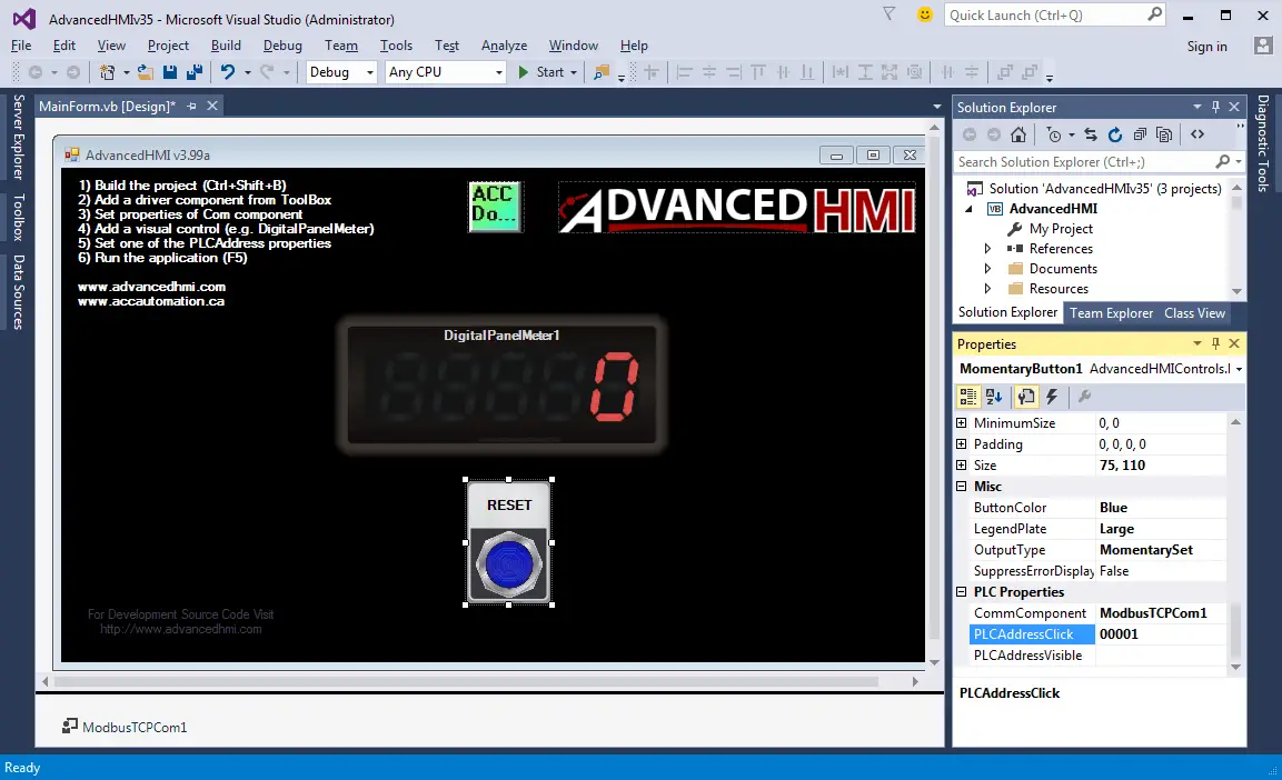
Run the application by selecting ‘Start’ from the top menu. This also can be started by hitting ‘F5’. The form will then show in a separate window, and the panel meter will increment the value. When you click the panel meter, the reset button will reset the matter to the one entered.
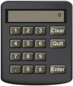
A keypad will appear on your screen when you hit the panel meter on display. Enter the new value and then select ‘Enter.’ The new value will appear in MHR2 in the Do-More PLC.
Watch on YouTube: Create a PLC with HMI Training and Learning Environment Free
If you have any questions or need further information, please get in touch with me.
Thank you,
Garry
If you’re like most of my readers, you’re committed to learning about technology. Numbering systems used in PLCs are not challenging to learn and understand. We will walk through the numbering systems used in PLCs. This includes Bits, Decimals, Hexadecimal, ASCII, and Floating Points.
To get this free article, subscribe to my free email newsletter.
Use the information to inform other people how numbering systems work. Sign up now.

The ‘Robust Data Logging for Free’ eBook is also available as a free download. The link is included when you subscribe to ACC Automation.