
We are using Modbus TCP protocol, reading ten registers in the PLC, and displaying a bar graph in Excel. e will use Visual Basic for Applications (VBA) to communicate with a PLC. Previously we have used VB6 to communicate Modbus TCP.
Sequence for Modbus TCP on Excel using VBA
The following steps will be done:
- Explain the Modbus TCP protocol
- Install OstroSoft Winsock Component
– Winsock API Calls for communication on the network - Develop the Excel and VBA application
(Microsoft Excel 2010) - Communicate to the PLC and sample code
(Do-More Simulator)
What is Modbus TCP (Ethernet)
The Modbus TCP/IP or Modbus TCP is a protocol for communications over TCP/IP networks. This is done on port 502. Modbus TCP does not require a checksum calculation as lower layers provide checksum protection. You can think of this as a letter being sent, and Ethernet TCP/IP acts like an envelope for the Modbus Commands. I will not go into the details of the communication protocol, but here are some links to references:
Introduction to Modbus TCP/IP
Simply Modbus – Modbus TCP
Winsock Component – Excel VBA Modbus TCP
OstroSoft Winsock Component
OSWINSCK.dll is a wrapper for the Winsock API and helps programmers abstract from the complexity of API calls and focus on application functionality. Works with programming and scripting languages supporting COM.
You must download and install the OstroSoft Winsock Component on your computer.
For use with .NET, Visual Basic 4 or 5, Visual C++, ASP, VBA, VBScript, JavaScript, or any other language, supporting COM:
1. Download oswinsck.exe

2. Run the downloaded file from Windows Explorer or command-line
Hit OK
I use the default directories where the program will be installed. Click the button to install.
Leave the program group to the default, so I know what the program is after installation. Click continue.
Click OK
The OstroSoft Winsock Component is now installed.
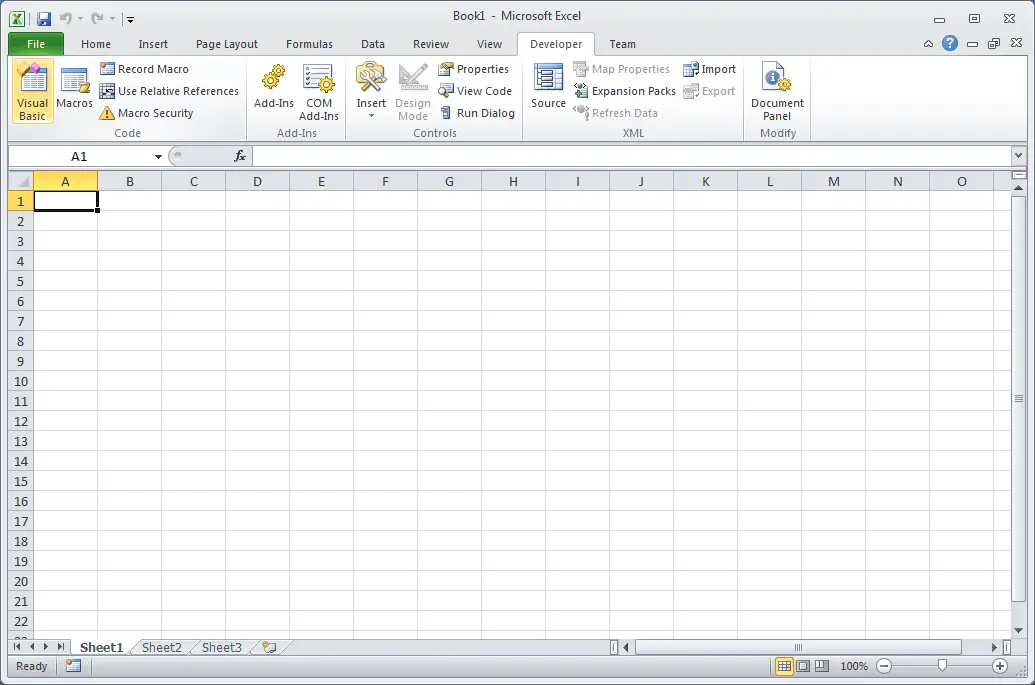
Start Microsoft Excel
Select ‘Developer’ along with the top tabs.
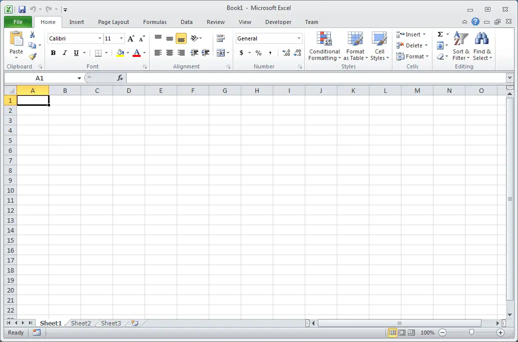
If the Developer tab is not present, then we must turn on the developer tab.
Select File | Options 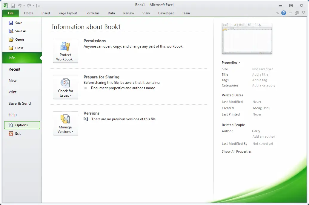 Select ‘Customize Ribbon’Check the ‘Developer’ under Main Tabs.
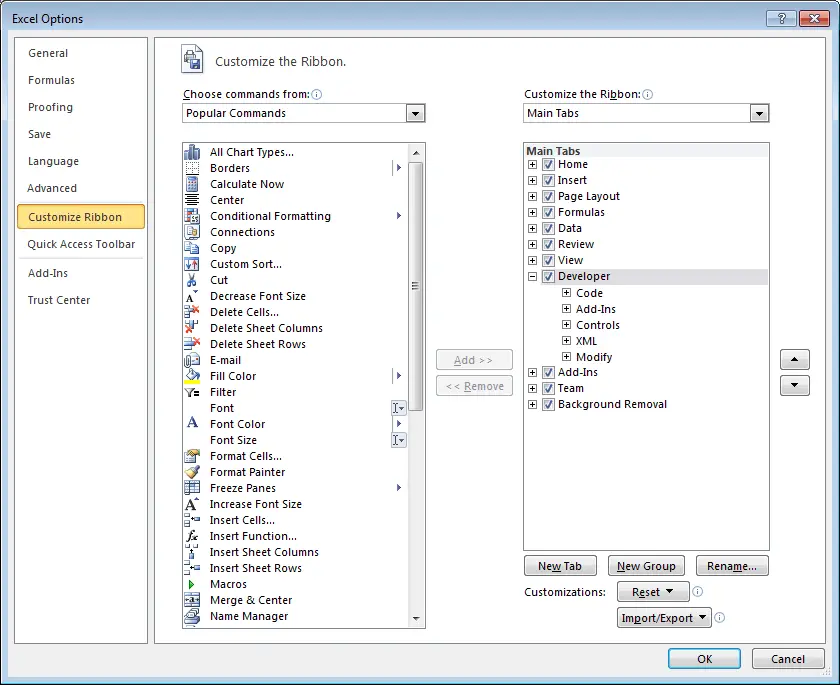
Under the Developer menu. Select ‘Visual Basic’
 The Visual Basic Editor window will now be displayed.
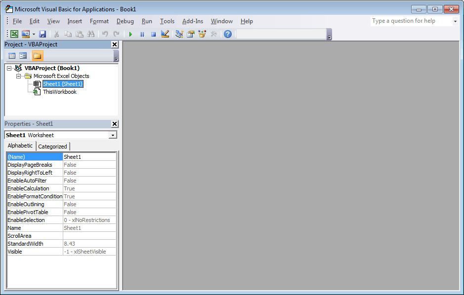
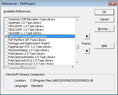
From the menu – Tools | References
We can now add the OstroSoft Winsock Component to our application.
Select OK
 Select Sheet1(Sheet1).
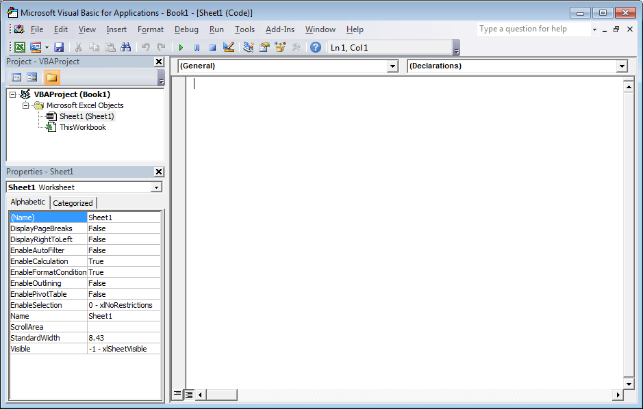
Visual Basic Code – Excel VBA for Modbus TCP
Now put the visual basic code in Sheet1(Sheet1)
Here is the code:
‘This example uses OstroSoft Winsock Component
‘http://www.ostrosoft.com/oswinsck.asp
Option Explicit
Dim bytesTotal As Long
Dim sPage As String
Dim MbusQuery
Dim returnInfo
Dim wsTCPgdb
Dim WithEvents wsTCP As OSWINSCK.Winsock
Dim SetObject
Dim RetrieveData
Private Sub CommandButton1_Click() ‘ Retrieve Data
On Error GoTo ErrHandler
Dim sServer As String
Dim nPort As Long
Dim StartTime
DoEvents
nPort = 502 ‘See configuration in Do-More Designer
‘Set the IP address of the PLC
sServer = Sheets(“Sheet1”).Range(“B4″) ‘”192.168.1.3”
RetrieveData = 1
CommandButton1.BackColor = “&H0000FF00” ‘Set a color to Green
‘Check to see if the object has been created. If not set wsTCP.
If SetObject = “” Then
Set wsTCP = CreateObject(“OSWINSCK.Winsock”)
wsTCP.Protocol = sckTCPProtocol
SetObject = 1
End If
‘Check the state of the TCP connection
‘0 sckClosed connection closed
‘1 sckOpen open
‘2 sckListening listening for incoming connections
‘3 sckConnectionPending connection pending
‘4 sckResolvingHost resolving the remote hostname
‘5 sckHostResolved remote host name successfully resolved
‘6 sckConnecting connecting to remote host
‘7 sckConnected connected to remote host
‘8 sckClosing Connection Is closing
‘9 sckError error occurred
‘If TCP is not connected, try to connect again.
If wsTCP.State <> 7 Then
If (wsTCP.State <> sckClosed) Then
wsTCP.CloseWinsock
End If
‘Open the connection
wsTCP.Connect sServer, nPort
StartTime = Timer’ Use the timer to determine if a connection cannot be made
Do While ((Timer < StartTime + 2) And (wsTCP.State <> 7))
DoEvents
Loop
If (wsTCP.State = 7) Then
Else
Exit Sub
End If
End If
‘If we are connected, then request the information.
If (wsTCP.State = 7) Then
MbusQuery = Chr(0) + Chr(0) + Chr(0) + Chr(0) + Chr(0) + Chr(6) + Chr(0) + Chr(3) + Chr(0) + Chr(0) + Chr(0) + Chr(20)
wsTCP.SendData MbusQuery ‘Send out the Modbus Information
‘Read the information
‘0000: Transaction Identifier
‘0000: Protocol Identifier
‘0006: Message Length (6 bytes to follow)
’00: The Unit Identifier
’03: The Function Code (read MHR Read Holding Registers)
‘0000: The Data Address of the first register
‘0020: The number of bytes to read
‘Write the information
‘0000: Transaction Identifier
‘0000: Protocol Identifier
‘0009: Message Length (6 bytes to follow)
’01: The Unit Identifier
’16: The Function Code (read Analog Output Holding Registers)
‘0000: The Data Address of the first register
‘0001: The number of registers to write
’02: The number of data bytes to follow
‘0030 The number to put into the register
‘Note: Addresses are offset by 1
‘ Example: MHR1 = Address 0000
‘ Example: MHR30 = Address 0029
End If
Exit Sub
ErrHandler:
MsgBox “Error ” & Err.Number & “:” & Err.Description
End Sub
Private Sub CommandButton2_Click() ‘ Stop the communication
RetrieveData = 0
CommandButton1.BackColor = “&H8000000F”‘ Set the default color
End Sub
Private Sub wsTCP_OnDataArrival(ByVal bytesTotal As Long)
Dim sBuffer
Dim i
Dim MbusByteArray(500)
Dim h As Integer
Dim txtSource
wsTCP.GetData sBuffer
txtSource = txtSource & sBuffer
Dim j As Byte
returnInfo = “”
For i = 1 To bytesTotal
wsTCP.GetData j, vbByte
MbusByteArray(i) = Asc(Mid(sBuffer, i, 2))
returnInfo = returnInfo & Asc(Mid(sBuffer, i, 2))
Next
txtSource = returnInfo
txtSource = Val(Str((MbusByteArray(10) * 256) + MbusByteArray(11)))
Sheets(“Sheet1”).Range(“B10”) = Val(Str((MbusByteArray(10) * 256) + MbusByteArray(11)))
Sheets(“Sheet1”).Range(“B11”) = Val(Str((MbusByteArray(12) * 256) + MbusByteArray(13)))
Sheets(“Sheet1”).Range(“B12”) = Val(Str((MbusByteArray(14) * 256) + MbusByteArray(15)))
Sheets(“Sheet1”).Range(“B13”) = Val(Str((MbusByteArray(16) * 256) + MbusByteArray(17)))
Sheets(“Sheet1”).Range(“B14”) = Val(Str((MbusByteArray(18) * 256) + MbusByteArray(19)))
Sheets(“Sheet1”).Range(“B15”) = Val(Str((MbusByteArray(20) * 256) + MbusByteArray(21)))
Sheets(“Sheet1”).Range(“B16”) = Val(Str((MbusByteArray(22) * 256) + MbusByteArray(23)))
Sheets(“Sheet1”).Range(“B17”) = Val(Str((MbusByteArray(24) * 256) + MbusByteArray(25)))
Sheets(“Sheet1”).Range(“B18”) = Val(Str((MbusByteArray(26) * 256) + MbusByteArray(27)))
Sheets(“Sheet1”).Range(“B19”) = Val(Str((MbusByteArray(28) * 256) + MbusByteArray(29)))
DoEvents
‘Determine if we retrieve the data again.
If RetrieveData = 1 Then
Call CommandButton1_Click
End If
End Sub
Private Sub wsTCP_OnError(ByVal Number As Integer, Description As String, ByVal Scode As Long, ByVal Source As String, ByVal HelpFile As String, ByVal HelpContext As Long, CancelDisplay As Boolean)
MsgBox Number & “: ” & Description
End Sub
Private Sub wsTCP_OnStatusChanged(ByVal Status As String)
Debug.Print Status
End Sub
Note: The program utilizes the CHR and STR functions to convert the data from binary to ASCII and back.
The highest value of a byte of data is 256. This is why we have to multiply the highest significant byte with 256
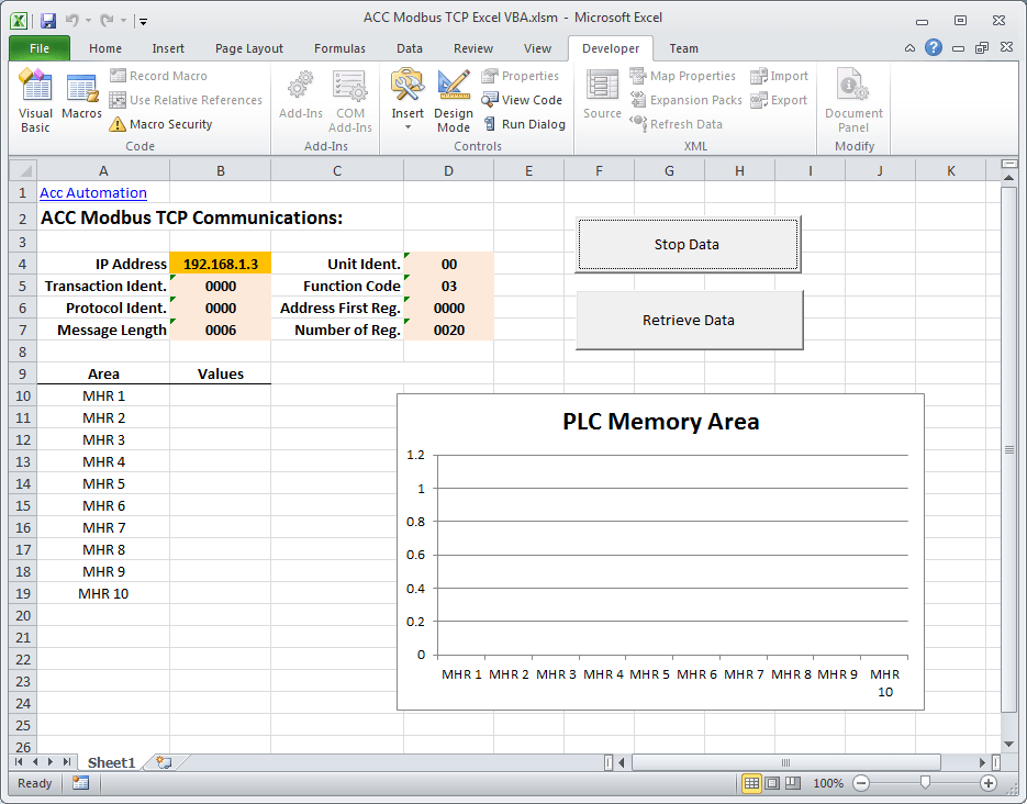
Interface:
Go back to Sheet1, and we can now put what we want to see on the worksheet.
Note the following:
IP Address = B4
MHR 1 to 10 values located at B10 to B19
‘Stop Data’ – CommandButton2
‘Retrieve Data’ – CommandButton1
Communication with the PLC
Start the Do-More Designer software.
Under the Project Browser, select ‘System Configuration.’
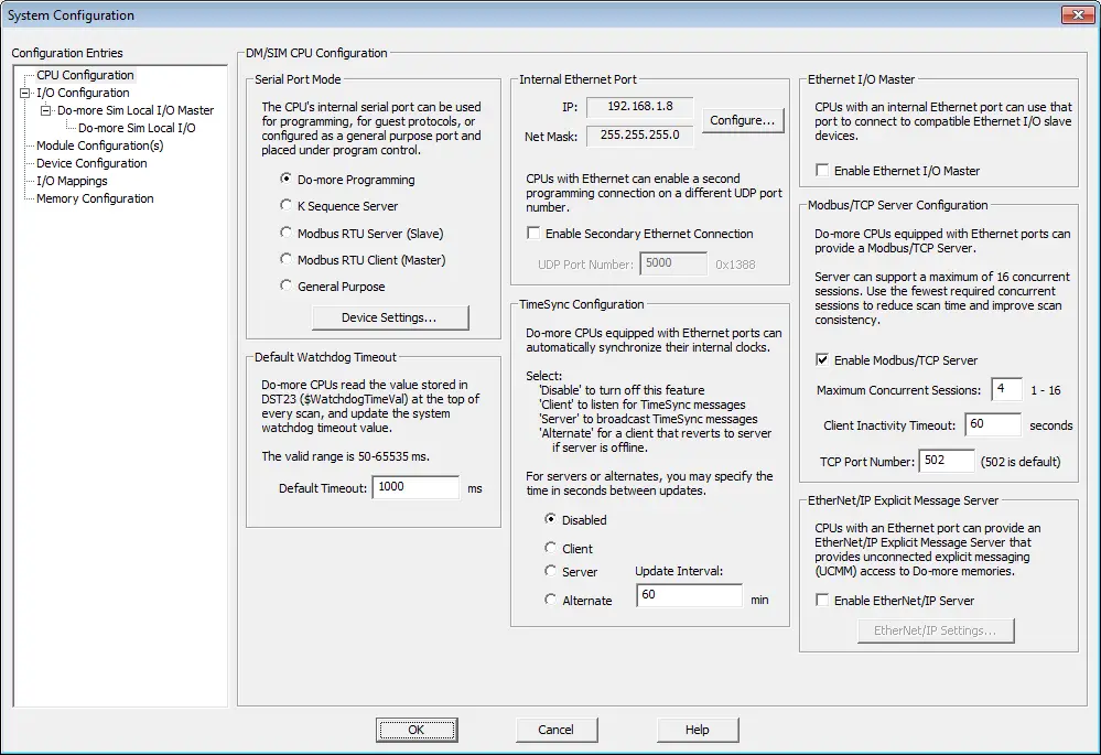
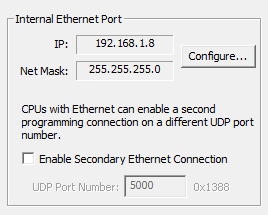
Make a note of the IP address. If you are running the simulator, then this is automatically filled in.
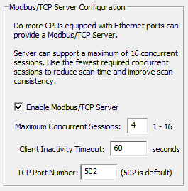
Ensure that the Enable Modbus/TCP Server is checked. Also, make sure that the TCP Port Number is 502.
The sample PLC program will write values from 0 to 4000. These values will be put in MHR 1 to MHR 10.
Here is the first couple of rungs of the PLC program. It will use clock bit flags to increment the MHR 1 channel. When it reaches a value above 4000, a move instruction will put a 0 back into MHR 1.
If input X0 turns on, the value in XW0 will be moved into MHR1, and the previous clock bit will not be in effect. Discounts will be between 0 and 4096. (12-bit resolution)
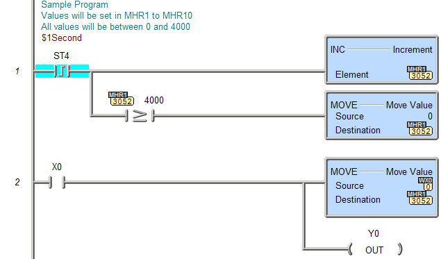
This is repeated with different internal clock bit flags up to MHR10.
Running the program will produce the following:
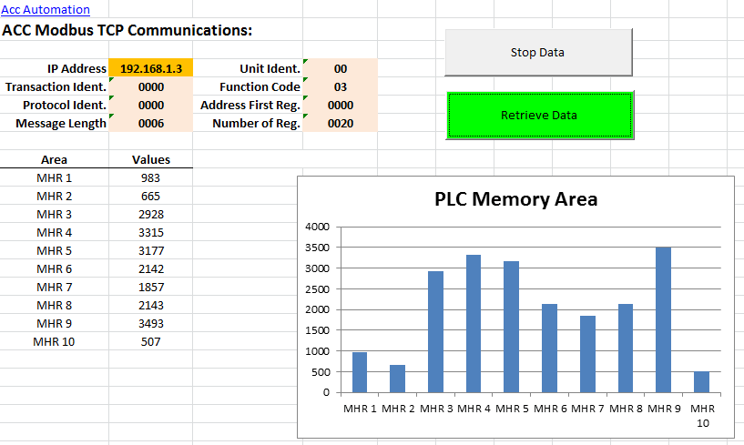
As you can see, the Modbus TCP protocol is easy to implement with visual basic for applications.
Download the PLC program and Excel file.
Additional Information:
Excel – Conditional Movement of Data
Watch on YouTube: How to Implement Modbus TCP Protocol using VBA with Excel
If you have any questions or need further information, please get in touch with me.
Thank you,
Garry
If you’re like most of my readers, you’re committed to learning about technology. Numbering systems used in PLCs are not challenging to learn and understand. We will walk through the numbering systems used in PLCs. This includes Bits, Decimals, Hexadecimal, ASCII, and Floating Points.
To get this free article, subscribe to my free email newsletter.
Use the information to inform other people how numbering systems work. Sign up now.

The ‘Robust Data Logging for Free’ eBook is also available as a free download. The link is included when you subscribe to ACC Automation.