The Do-More PLC P2P Modbus Scanner Communication within the Do-More Designer Software offers a powerful and streamlined solution for integrating Modbus devices into your PLC system. With its advanced features and seamless integration capabilities, this Modbus Application empowers you to unlock new levels of efficiency and productivity in your industrial automation applications. A peer-to-peer (P2P) service is a decentralized platform whereby two individuals interact directly with each other without intermediation by a third party.
One of the key advantages of the Do-More PLC Modbus Scanner Communication is its ability to establish peer-to-peer (P2P) communication with Modbus devices. This means the module can directly communicate with Modbus devices on the same network without a supervisory control system. This streamlined communication process allows for faster data exchange and reduces the complexity of the overall system architecture.
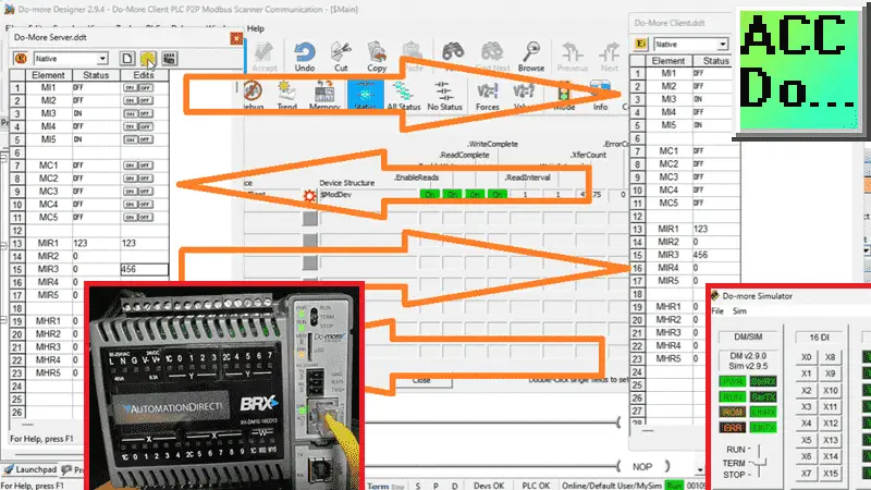
We will demonstrate how the Do-More Designer Simulator PLC communicates with the BRX Do-More PLC. This will be done via the Modbus IO Scanner in the programming software. The Modbus TCP protocol will read and write 100 discrete bits and registers. Let’s get started.
Previously, we discussed the BRX Do-More PLC using Modbus IO Scanner Profile with a Solo process temperature controller and click plus plc. Here is the video of that being done. Serial Modbus RTU was also done using the IO Scanner. This video will show communication to the Solo temperature controller using RS485 (twisted pair).
Our entire BRX Do-More Series of PLC can be found here.
The Do-More FAQ can be helpful if you use the Do-More platform.
What is Modbus?
Modbus is a communication protocol widely used in industrial automation due to its simplicity and efficiency. The media (wiring) used depends on the actual type of Modbus protocol used.
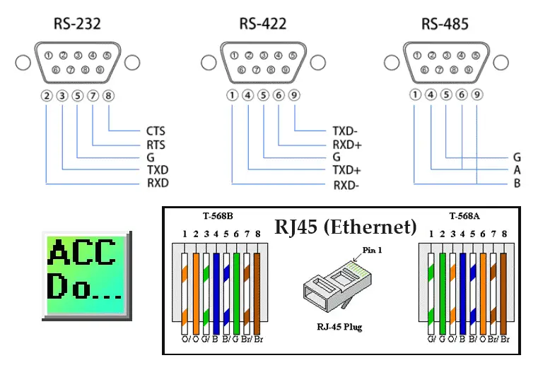
Serial communication will usually use RS232 or RS485 media. The Modbus Protocol is RTU or ASCII. All devices must have the same wiring and Modbus Protocol before communication can occur.
Ethernet communication will use an RJ45 media. The CAT Ethernet cable used will depend on your actual network and location. Modbus TCP protocol is used on this network.
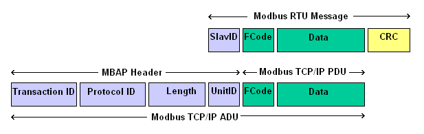
Modbus is a Master (Client)/Slave (Server) protocol. In a serial environment, there can be only one Master (Client). The Slaves (Servers) will respond only when data is requested. In an Ethernet environment, the Client/Server works the same way; however, because of the OSI physical model, multiple Clients can be used. This ensures that when multiple commands are received simultaneously, they are handled in order.
What are Modbus Addresses?
The four types of addresses referenced in Modbus devices are:
• Coil (Discrete Output)
• Discrete Input (or Status Input)
• Input Register
• Holding Register
It is important to find out the Modbus Addresses that are available in all of the Slave (Server) units on your network. The Do-More Series of PLCs uses a fixed dedicated Modbus memory area. This area can be seen in the following chart.
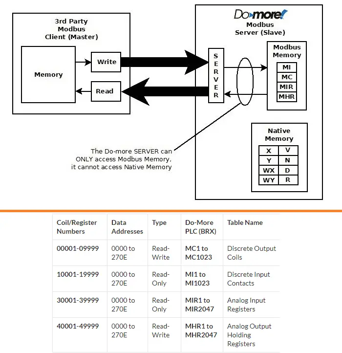
In our example, we will read and write 100 discrete bits of information and 100 registers. Using the Do-More Modbus registers, we will read 100 MI discrete input contacts and 100 MIR input registers. We will also write 100 MC discrete output coils and 100 MHR output holding registers. This is all from the Modbus TCP Client PLC. (PLC Simulator)
Programming the Modbus Server PLC
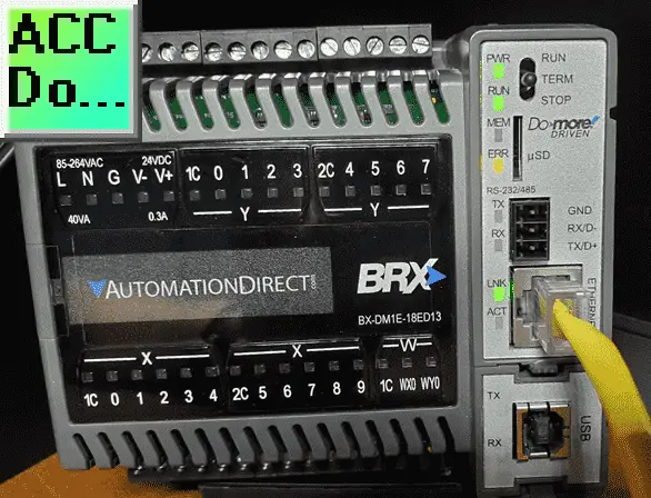
We will start with programming the Modbus Server PLC. This is the physical BX-DM1E-18ED13 BRX PLC. Start the Do-More Designer programming software. Ensure that the PLC is powered up and connected using an Ethernet cable. Select the “New Online” icon on the main ribbon menu.
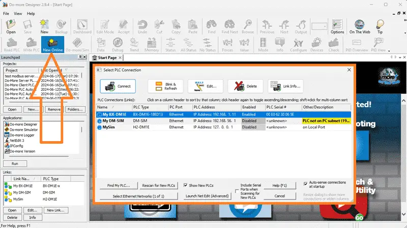
The “Select PLC Connection” window will be displayed. All of the devices that can be connected will be automatically displayed. You will see our PLC IP address and MAC (physical) address. If you are unsure if this is the controller you want to program, select the “Blink & Refresh” button.
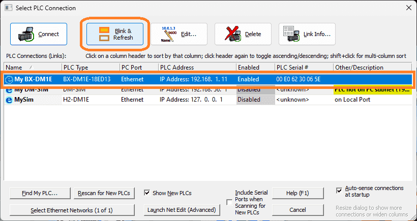
This will blink the “ERR LED” on the CPU yellow for 15 seconds.
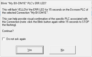
A warning message will appear. Select “Yes” to start flashing the CPU LED.
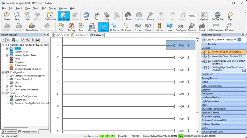
Once we verify that we have the correct PLC to program, we will go to the edit mode and place an “END” statement instruction for our logic.
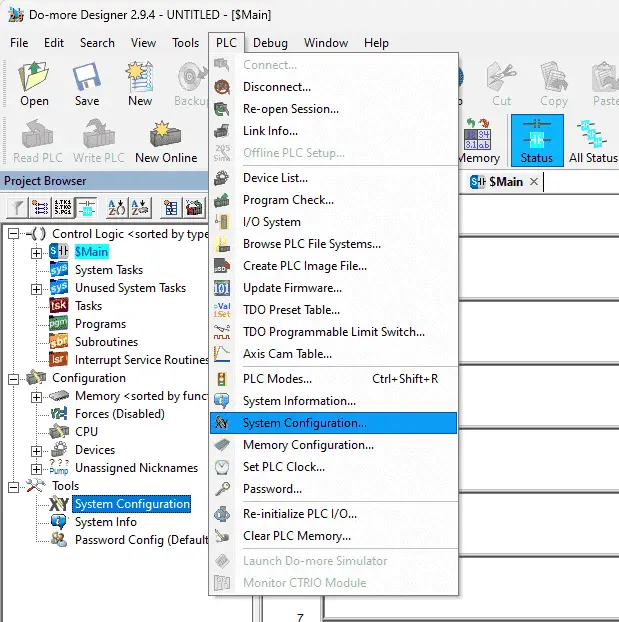
Select “System Configuration…” from the main menu | PLC or under the tools menu in the project browser.
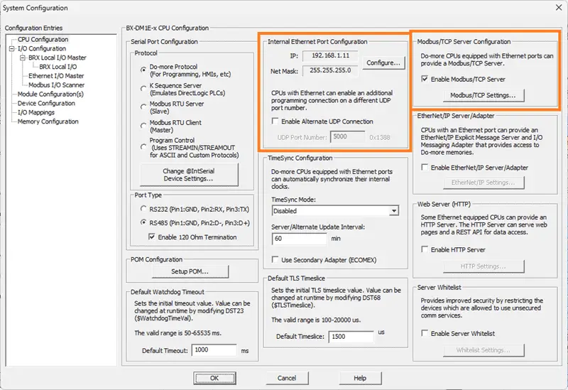
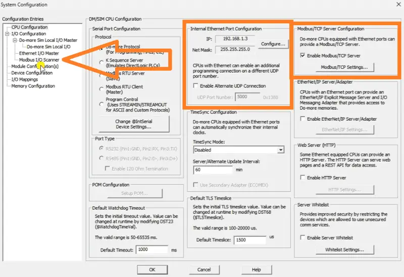
The system configuration window will now be displayed. This will show you the IP address and ensure we have selected the Modbus TCP Server option for this PLC.
Transfer and save the Modbus Server PLC setup and program.
Programming the Modbus Client PLC
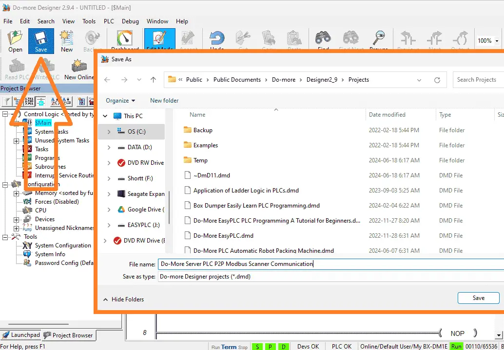
We can now program our Modbus TCP Client PLC. This is the controller that will handle all of the communication on the network. Select the “New” icon on the main menu ribbon of the Do-More designer programming software.
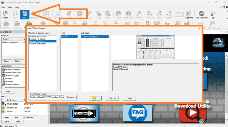
The New Offline Project window will be displayed. Select the Do-more Simulator and name the project. Select OK.
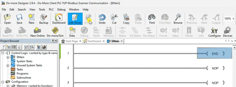
Like the server PLC, we will have an END statement for our ladder logic program.
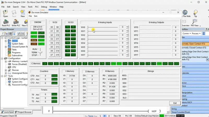
Select the Do-More/Sim icon on the main menu ribbon. This will start the Do-More Simulator. The PLC simulator will run independently of the Do-More designer programming software.
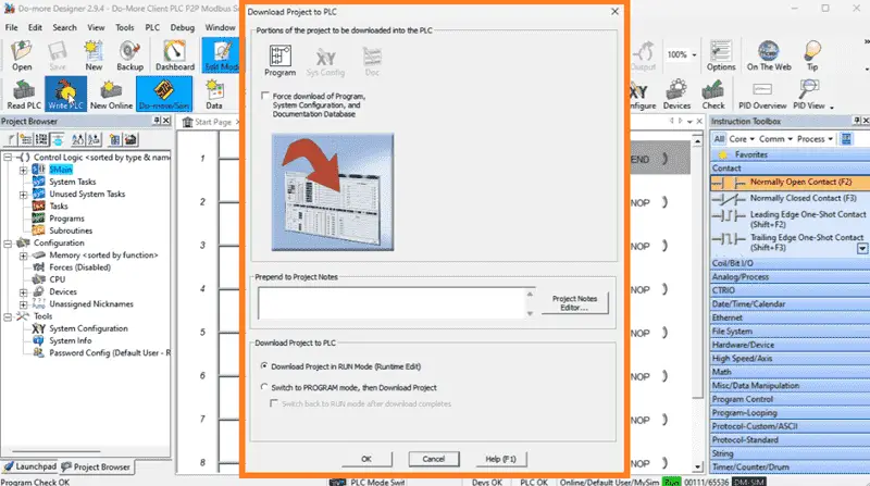
Returning to the programming software, we can select the “Write PLC” icon on the main menu ribbon. This will transfer our program to the simulator.
Select “System Configuration…” from the main menu | PLC or under the tools menu in the project browser.

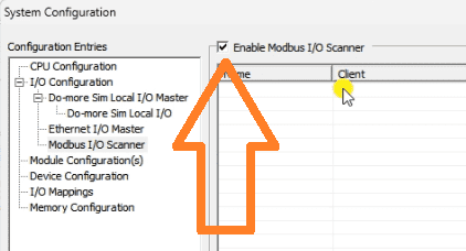
The system configuration window will now be displayed. This will show you the IP address. The IP address will be the same as the computer running the PLC simulator. Select Modbus I/O Scanner under the I/O configuration menu on the left side.
Select the “Enable Modbus I/O Scanner”. This will allow us to use the scanner.
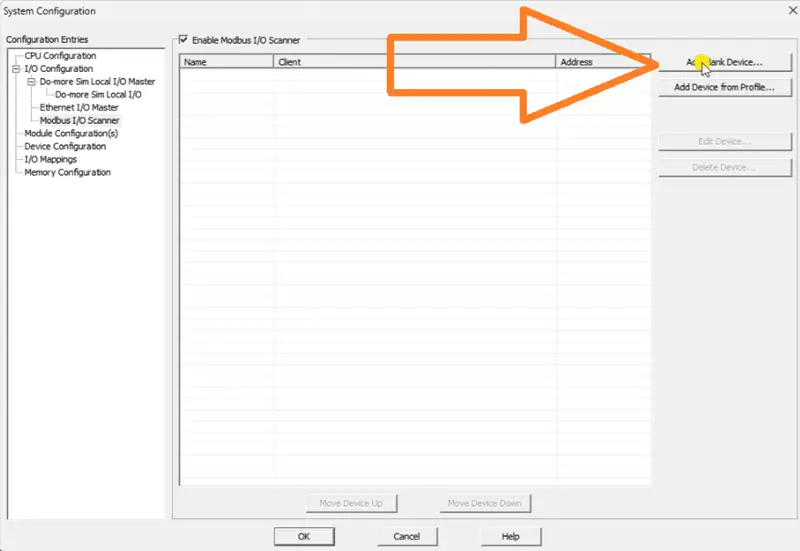
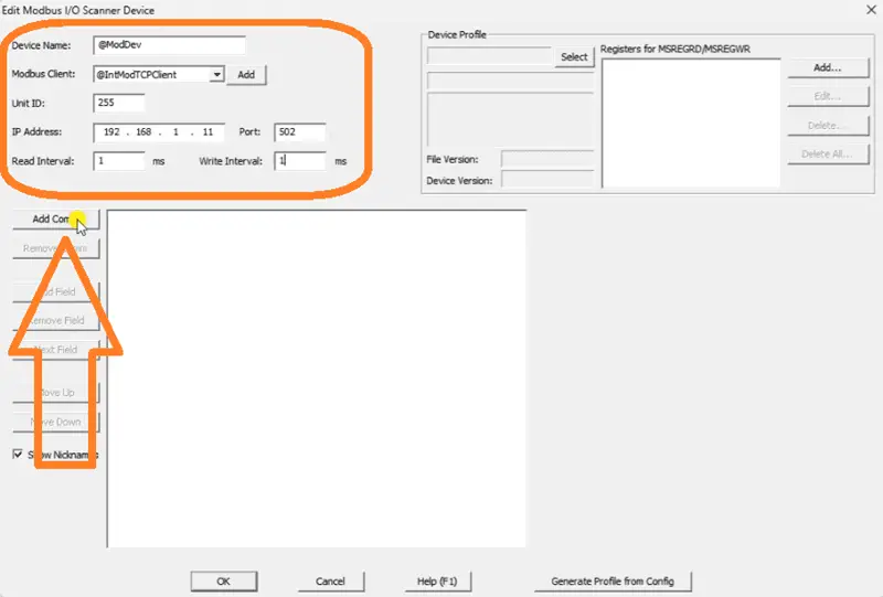
On the right-hand side of the window, you will see two options. “Add Device from Profile…” will show you devices that have been preprogrammed so you can communicate with different equipment. We demonstrated this before when communicating with a Solo Process Temperature Controller. Select the “Add Blank Device…”.
Enter the IP Address of the server PLC. We will also change the read and write intervals to the minimum time. This is 1 millisecond.
Select “Add Comm”.
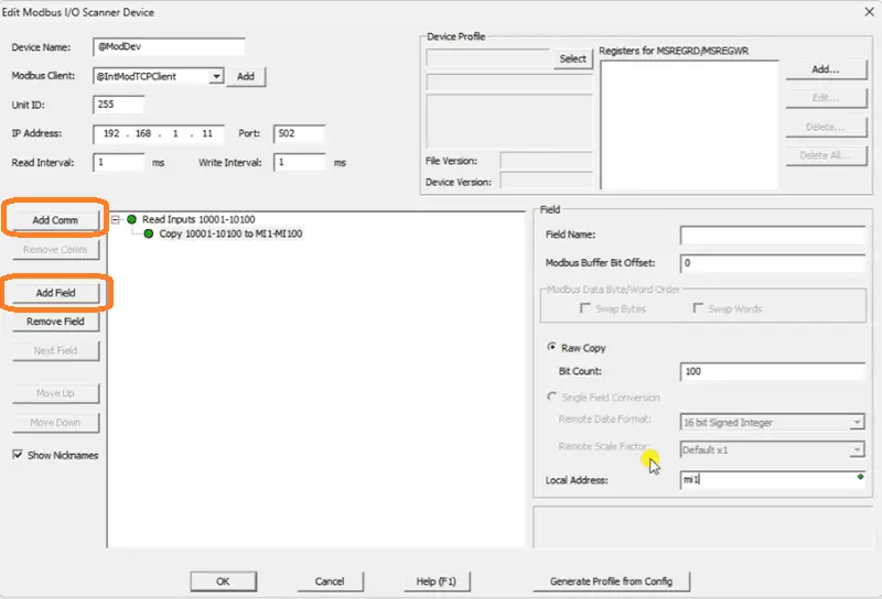
Select the Read Inputs and then select the “Add Field” button. Set the bit count to 100. We can now specify where we want to put the data. Enter MI1.
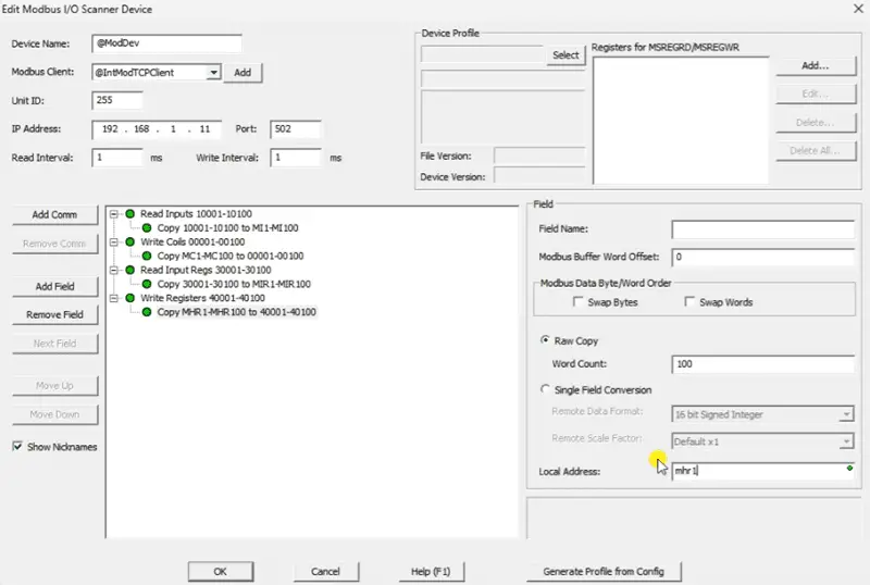
We can now enter the other communication and fields for our Modbus Scanner.
Read inputs 10001 to 10100 and store in MI1 to MI100
Write coils 00001 to 00100 from MC1 to MC100
Read input registers 30001 to 30100 and store in MIR1 to MIR100
Write registers 40001 to 40100 from MHR1 to MHR100
Select OK.
A warning message will be displayed indicating that the system configuration has changed.
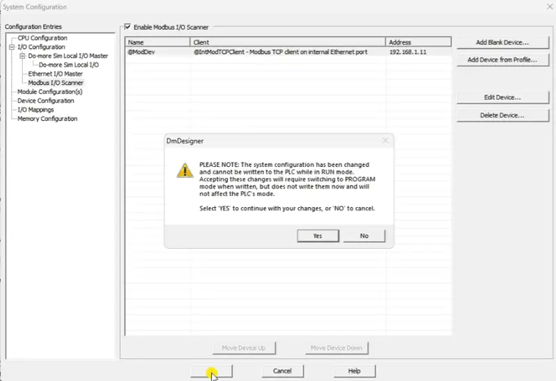
Select OK and download the program to the Client PLC Simulator.
Monitoring the P2P Modbus TCP Communication
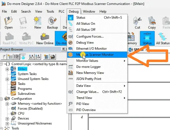
Ensure that both the PLC and simulator are running. We can now monitor the P2P Modbus TCP communication by monitoring the scanner. Call the Mobus Scanner Monitor by selecting it from the main menu | Debug.
The Modbus Scanner Monitor will show you the bit flags, errors, and counts. This will help to ensure that communications are working correctly.
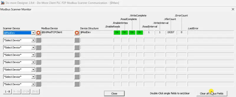
Once the communications have been established, we can now go ahead and test the information being exchanged.
Testing the Network
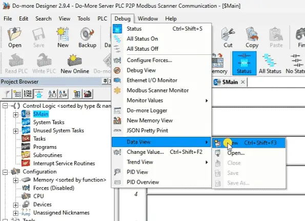
We can test our network and the information being exchanged using each PLCs’ Data View option.
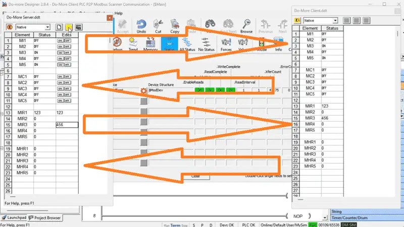
Here is the Do-More Server data view window. You will see that we have monitored the first 5 bits and registers.
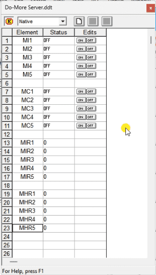
Here is the Do-More Client data view window. We are monitoring the same first 5 bits and registers.
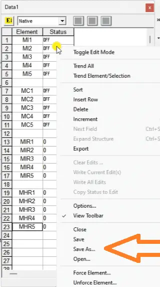
As we change the Server bits MI1 to MI5 and registers MIR1 to MIR5, they will be seen in the Client bits MI1 to MI5 and registers MIR1 to MIR5.
As we change the Client bits MC1 to MC5 and register MHR1 to MHR5, they will be seen in the Server bits MC1 to MC5 and registers MHR1 to MHR5.
The Do-More PLC P2P Modbus Scanner Communication provides a versatile and adaptable solution for their communication needs. It offers seamless integration with the Do-More PLC platform, allowing you to leverage the full capabilities of the PLC system for your Modbus communication requirements. This Modbus Scanner integration simplifies configuration and setup, making it easy to get up and running quickly with Modbus devices.
Watch the video below to see how to communicate using a Modbus IO scanner for Do-More PLC P2P Modbus Communication.
Download the BRX Do-More programs here including the Data View of both PLCs.
BRX Series PLC from Automation Direct – Power to deliver
Overview Link (Configure and purchase a system)
Manuals and Product Inserts (Installation and Setup Instruction)
Do-More Designer Software (Free Download Link) – The software will contain all the instruction sets and help files for the BRX Series PLC.
Watch on YouTube: Do-More PLC P2P Modbus Scanner Communication
If you have any questions or need further information, please contact me.
Thank you,
Garry
If you’re like most of my readers, you’re committed to learning about technology. Numbering systems used in PLCs are not challenging to learn and understand. We will walk through the numbering systems used in PLCs. These numbering systems include Bits, Decimal, Hexadecimal, ASCII, and Floating Point. To get this free article, subscribe to my free email newsletter.
Use the information to inform other people how numbering systems work. Sign up now. The ‘Robust Data Logging for Free’ eBook is also available for free download. The link is shown when you subscribe to ACC Automation.