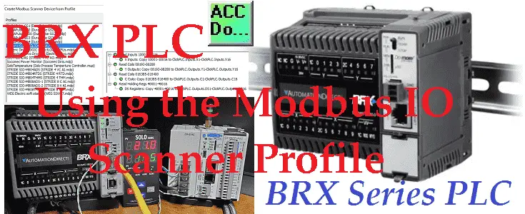
The Do-More Designer Programming Software (2.9) or higher includes a Modbus I/O Scanner with some profiles for Modbus Server (Slave) devices. This will greatly reduce the time it takes to implement and troubleshoot communications in your projects. Modbus communications are done independent of the PLC scan time and will have little or no ladder logic for the program.
 Last time we communicated to a Solo process temperature controller via Modbus RTU RS485. (twisted pair) We manually set the Modbus IO scanner, reading the present value (PV) and set value (SV) of the Solo. The writing of the set value (SV) located within the BRX Do-More controller was also done. This was all be done without using any ladder logic code. We will now use the Modbus profile in the Modbus IO Scanner to connect a Click Plus PLC to our RS485 network. Using the Modbus scanner to write and read instructions we will also show how to use the ladder logic code with our scanner. Let’s get started.
Previously in this BRX series PLC, we have discussed:
System Hardware – Video
Unboxing – Video
Installing the Software – Video
Establishing Communication – Video
Firmware Update – Video
Numbering Systems and Addressing – Video
First Program – Video
Monitoring and Testing the Program – Video
Online Editing and Debug Mode – Video
Timers – Video
Counters – Video
High-Speed IO – Video
Compare Instructions – Video
Math Instructions – Video
Program Control – Video
Shifting Instructions – Video
Drum Instruction – Video
Serial Communication – Modbus RTU to Solo Process Temperature Controller – Video
Data Logging – Video
Email – Text SMS Messaging Gmail – Video
Secure Email Communication Video
AdvancedHMI Communication – Modbus TCP – Video
Analog IO – System Configuration – Video
HTTP JSON Instructions – Video
Analog Dusk to Dawn Program – Video
INC DEC 512 Registers for DMX512 – Video
PID with PWM Output – Video
PID Ramp Soak Profile – Video
Do-More Simulator MQTT Publish / Subscribe – Video
BRX Do-More PLC MQTT Communications – Video
Stride Field Remote IO Modules Modbus TCP Ethernet
– Unboxing SIO MB12CDR and SIO MB04ADS Video
– Powering and Configuring Video
BRX Do-More PLC to Stride Field IO Modbus TCP – Video
BRX Do-More PLC Ethernet Remote IO Controller BX-DMIO
– Unboxing BX-DMIO Video
– Configuration and Programming Video
Modbus RTU TCP Remote IO Controller BX-MBIO
– Hardware Video
– Powering and Configuring Video
BRX Do-More PLC to Modbus Remote IO Controller BX-MBIO – Video
Modbus ASCII Protocol – Video
Peerlink Ethernet Communication – Video
HTTP Web Server – Video
Dynamic Web Pages – Video
BRX Do-More PLC FTP Client Get Put – Video
Do-More Designer Element Browser – Video
BRX Do-More PLC High-Speed Input Counter – Video
BRX Do-More PLC High-Speed Input Timer – Video
BRX Do-More PLC High-Speed Input Pulse Catch – Video
BRX Do-More Simple Modbus Serial Communication – Video
Our entire BRX Do-More series can be found here.
The programming software and manuals can be downloaded from the Automation Direct website free of charge.
Watch the video below to see the operation of the Modbus IO scanner profile on the BRX Do-More PLC. This will be Modbus RTU (RS485) to a Solo Process Temperature Controller and Click PLC.
Hardware and Wiring
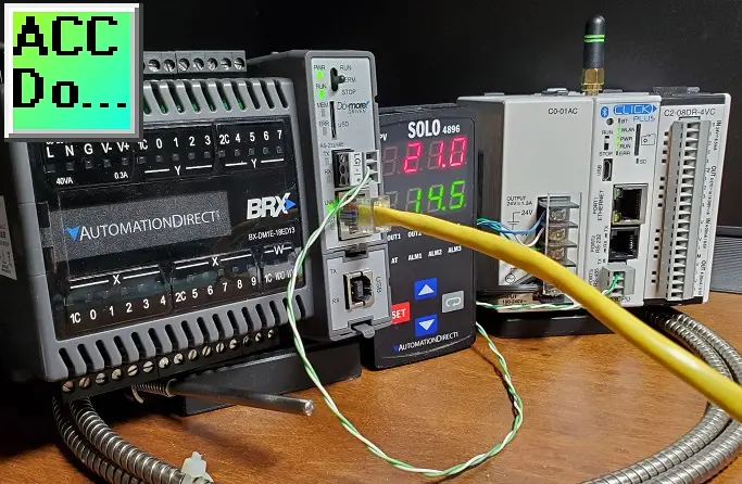
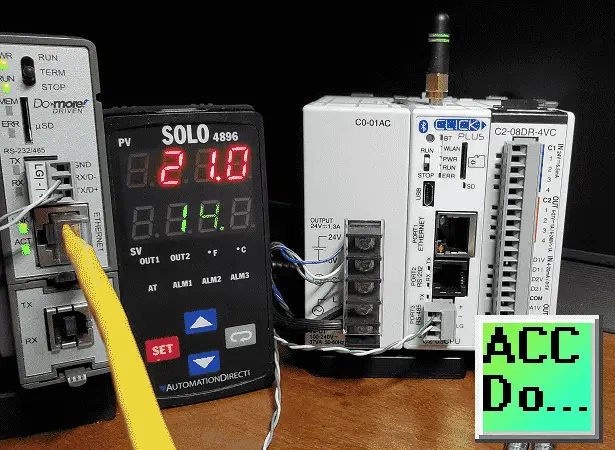
Using the same hardware as last time we will now add a Click PLC with an RS485 serial port.
 The twisted-pair wire is RS485. This has a network wire length of 1200 meters without repeaters. The wire is daisy-chained from device to device with termination on each end. This termination is a 120-ohm resistor. The termination as shown before is built into the BRX Do-More CPU.
RS485 is a one-to-many type of serial communication. (1:N) The protocol or information that we will be sent on this serial network is Modbus RTU.
Modbus RTU is a master-slave type of protocol. It can also be referred to as a Client/Server. There is only one master (Client) to several slave (Server) units. In our case, the BRX Do-More will be the master, communicating to the Solo and Click PLC slaves.
Click PLC RS485 Port Setup
In the Click, programming software calls up the COM Port Setup for Port 3 (RS485).
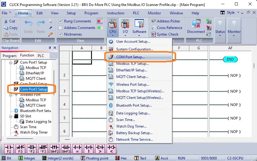 This can be done by selecting Com Port3 Setup from the function table in the navigation window, or by selecting COM Port Setup… under the CPU icon on the main screen. Alternatively, can also select COM Port under the Setup option on the main menu.
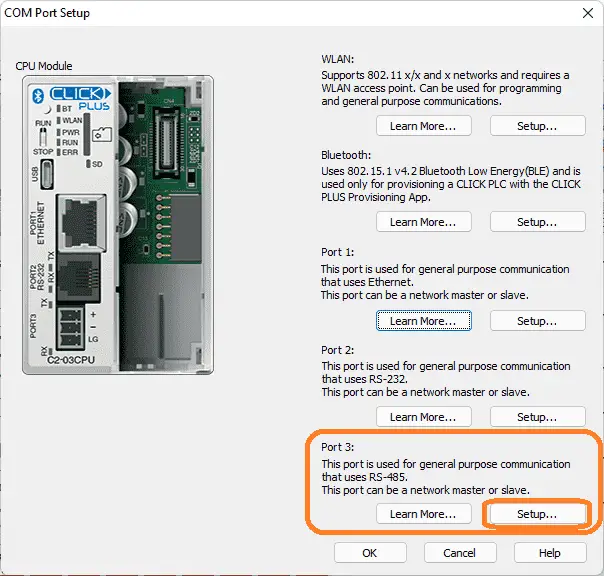 Port 3 uses RS-485. Select the setup button.
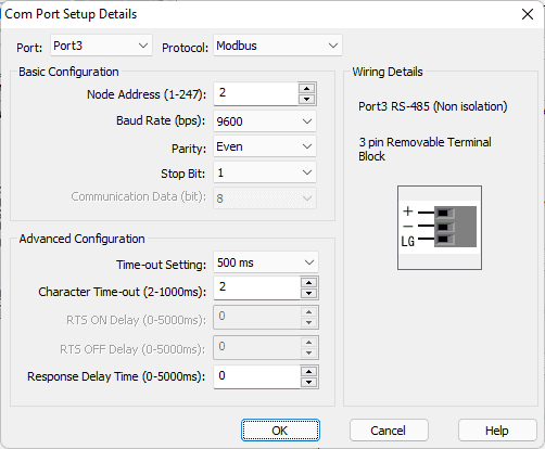 Under the basic protocol, ensure that the communication parameters match the settings from last time. 9600 baud, 8 data bits, even parity, and one-stop bit. The node address of the Click PLC will be set to 2. This will identify it on the network from the other slaves. Ensure that the protocol is set for Modbus. Select OK.
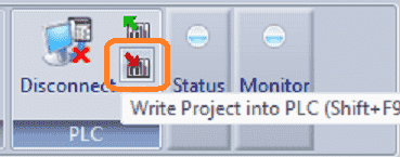 Write the project into the PLC using the download button. We are now set to communicate RS485 to the Click PLC.
Modbus IO Scanner Configuration
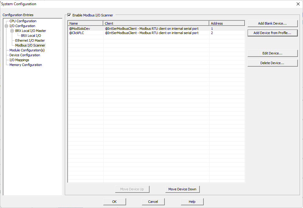
Call up the system configuration window in the Do-More Designer Programming Software.
 Select the Modbus I/O Scanner on the left side of the window, and then select the “Add Device from Profile…” button on the right-hand side.
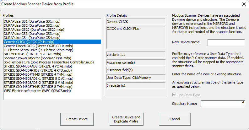 The crate Modbus scanner device from the profile window will now be displayed. Select the generic CLICK (CLICK CPUs.mdp) under profiles.
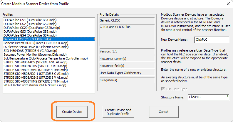 Enter ClickPLC under the new device and the structure name. Select Create Device.
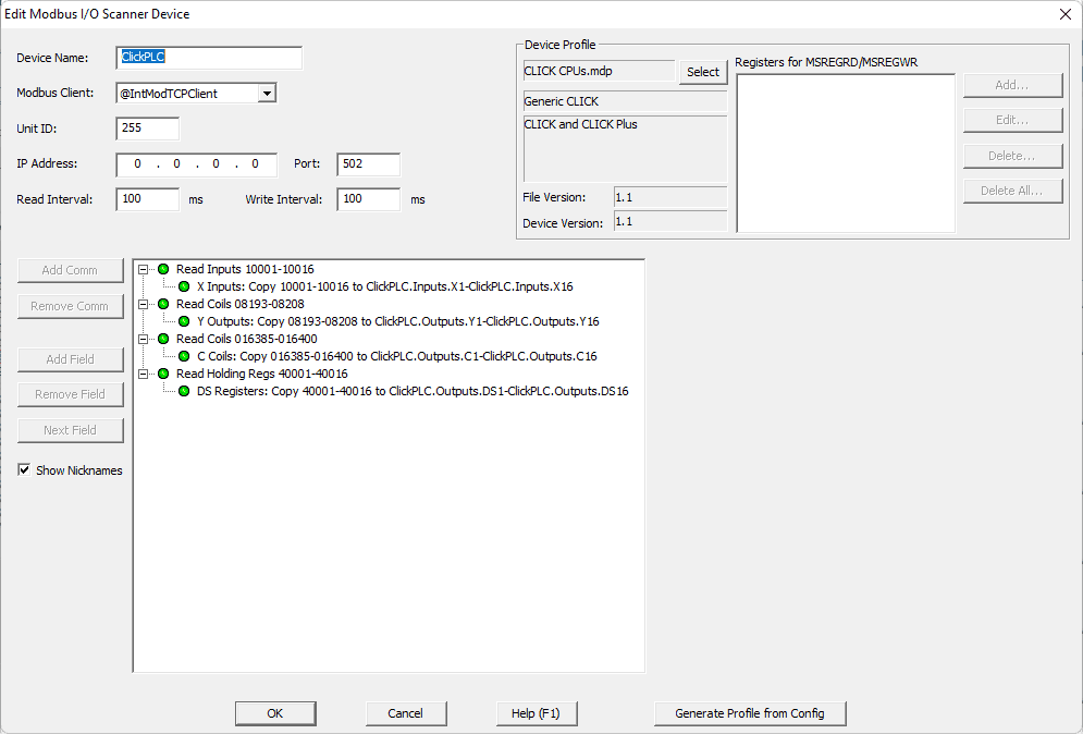 The edit Modbus I/O scanner device window will now be displayed for the profile selected. Under Modbus, the client selects the serial port. (@IntSerModbusClient) Set the unit ID number to 2 for the Click PLC.
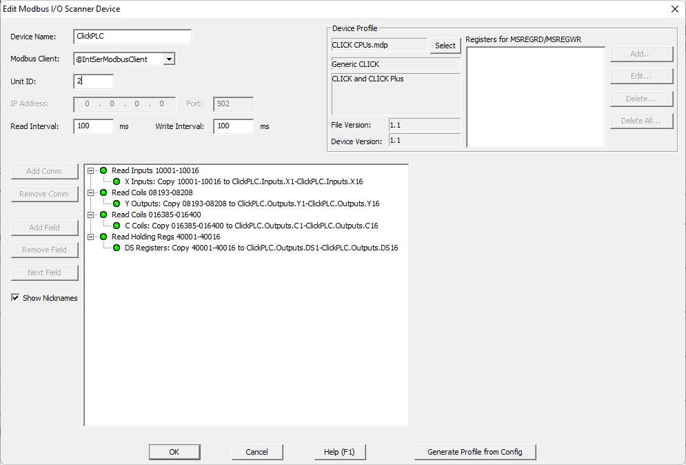 We will leave the read and write interval times the default 100 milliseconds. This profile consists of 4 different read commands. Information is read and then written into the structure assigned above.
X1 to X16 are read to ClickPLC.Inputs.X1 to ClickPLC.Inputs.X16
Y1 to Y16 are read to ClickPLC.Outputs.Y1 to ClickPLC.Outputs.Y16
C1 to C16 are read to ClickPLC.Outputs.C1 to ClickPLC.Outputs.C16
DS1 to DS16 are read to ClickPLC.Outputs.DS1 to ClickPLC.Outputs.DS16
Select OK.
Modification of the Solo Modbus IO Scanner
Previously we set up the Solo Modbus IO scanner (@ModSoloDev) to read the SV, PV, and write the SV. We want to be able to write the set value (SV) of the Solo from the BRX, Click, or the Solo itself.
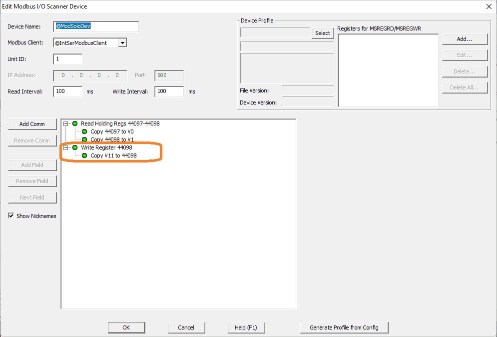 Currently, only the value in V11 will write the SV of the Solo. Every 100 milliseconds the value is written into the Solo process temperature controller. We must remove the write register instruction.
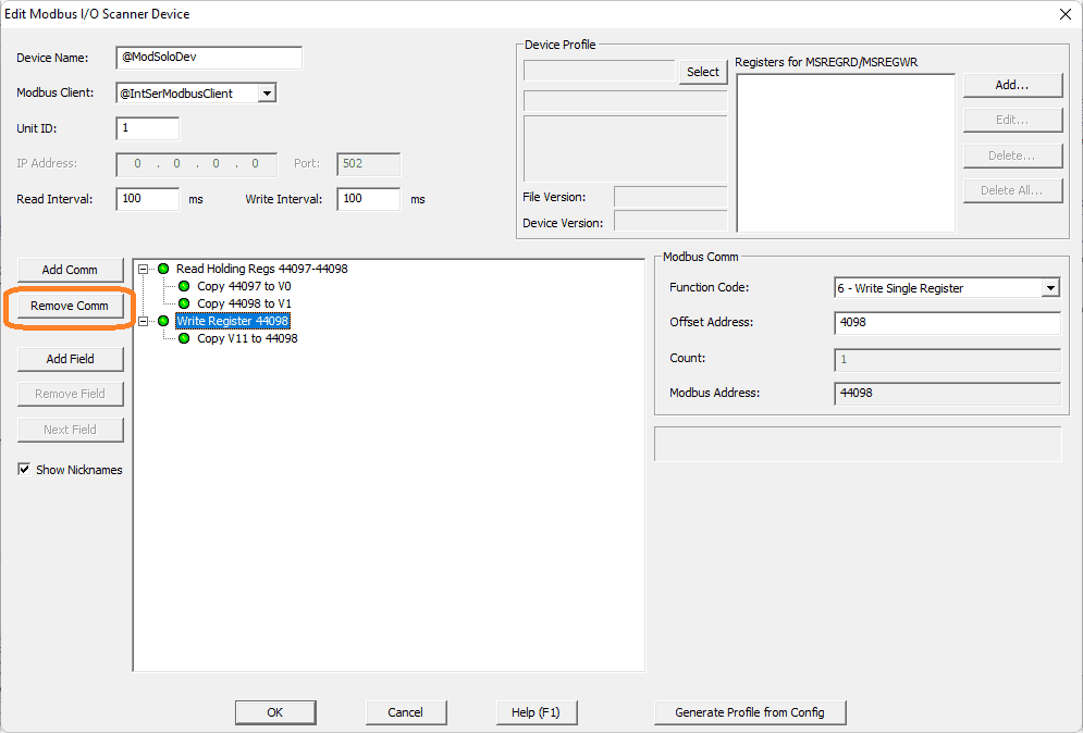 Click on the write register and select the remove comm button.
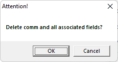 Select OK to delete the command all associated fields.
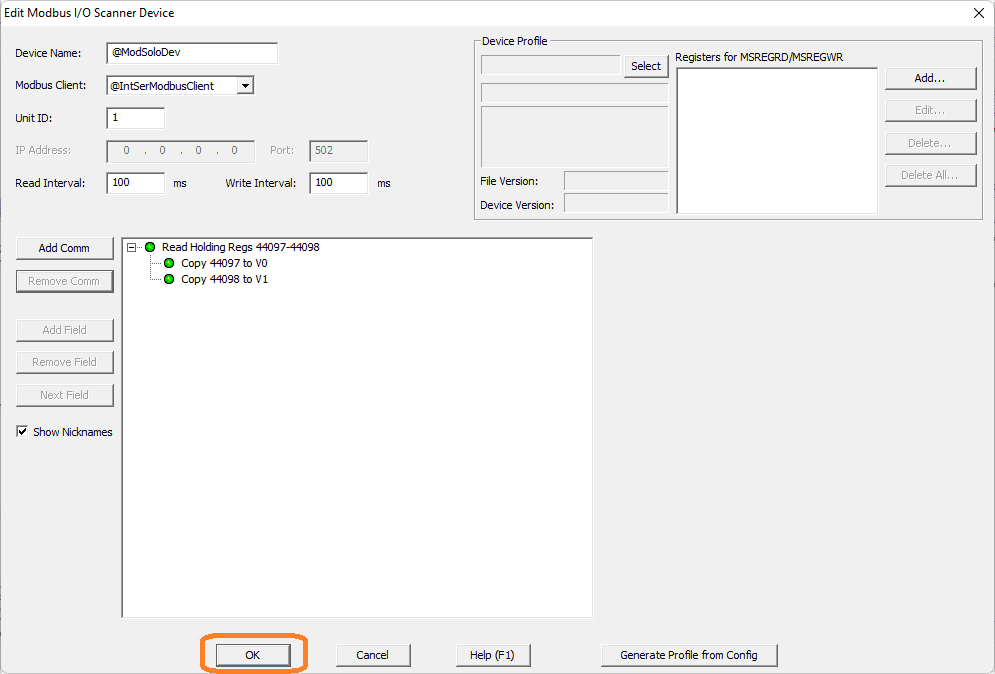 Here is the modified Solo Modbus IO scanner profile. Select OK.
We will be using the Modbus scanner register write instruction (MSREGWR) in the ladder logic to set the SV value of the Solo.
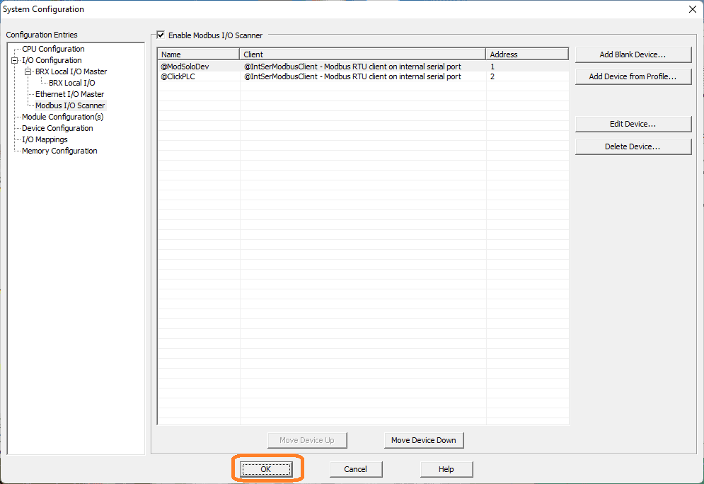 Select OK to close the system configuration window.
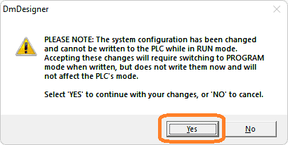 A warning window will be displayed indicating that the system configuration has changed, and this will need to be downloaded to the BRX Do-More PLC. Select yes.
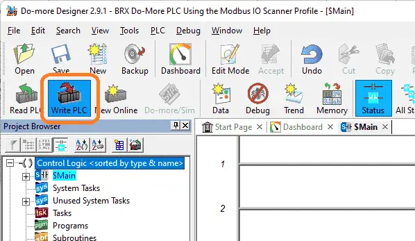 Select the write PLC icon on the main menu to transfer the current logic and configuration. We can now add the ladder logic.
BRX Do-More Ladder Logic
The BRX Do-More ladder logic program will basically move information around and write to the Solo set value. The SV value can be written from the BRX Do-More PLC (V2), Click PLC (DS3), or from the Solo process temperature controller itself.
 If the Click DS3 register is not equal to 0 then move the Click DS3 register to V2 of the BRX. V2 is the write register that we will use for the SV value.
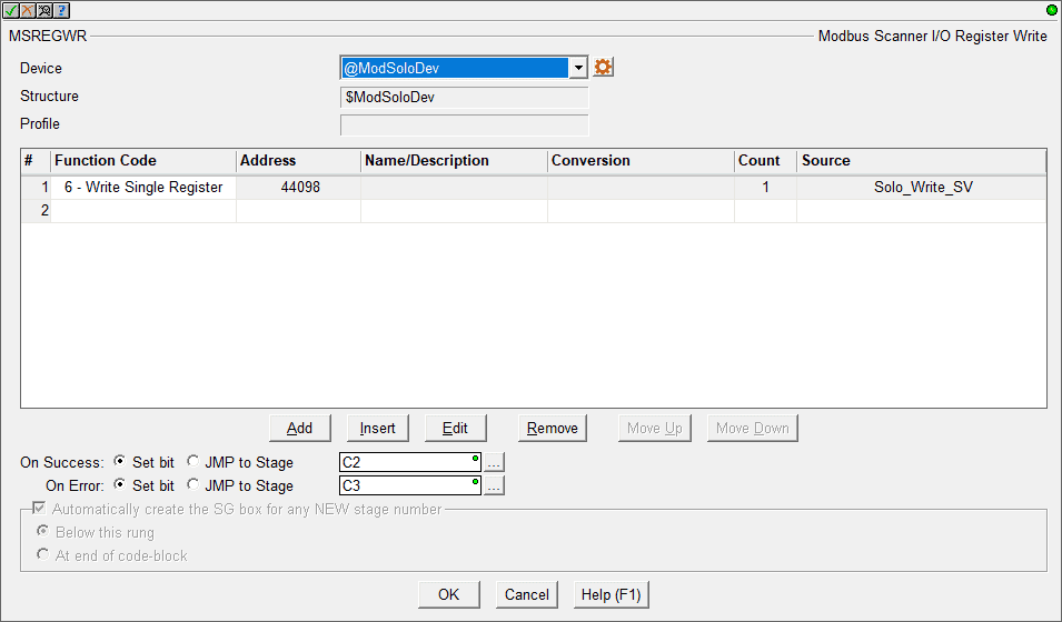 The Modbus I/O Scanner Register Write (MSREGWR) instruction is used to execute additional write commands to the scanner’s device’s normal processing. However, this instruction will allow us to determine when the instruction is to be implemented within the ladder logic code.
In our case, we will be using the @ModSoloDev device that we modified above. We will write a single register with the value from V2. (Solo_Write_SV)
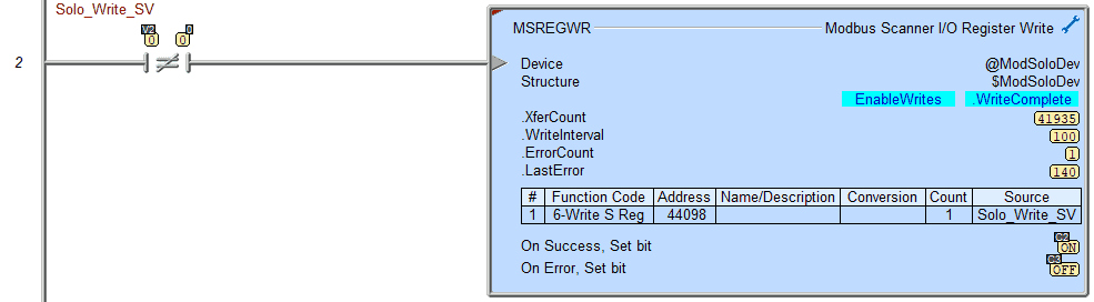 The MSREGWR instruction will be enabled when V2 is not equal to 0. When the instruction is executed successfully C2 will be turned on.
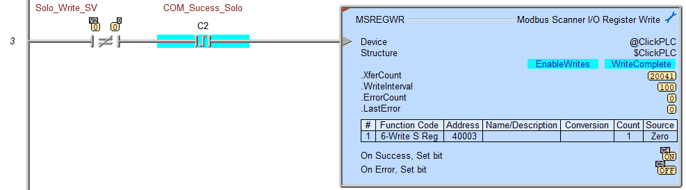 When the new SV is placed in the Solo, we then use the MSREGWR instruction again and this time zero out the DS3 register in the Click PLC. This will indicate that the writing process has been completed.
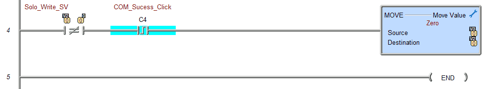 When the communication success bit is on for the zeroing of DS3 in the Click PLC, we then move 0 into V2 for the BRX PLC. Watch the video below to see this ladder logic program run and change the SV of the Solo through the Modbus IO Scanner.
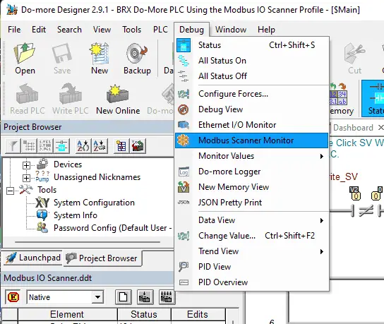
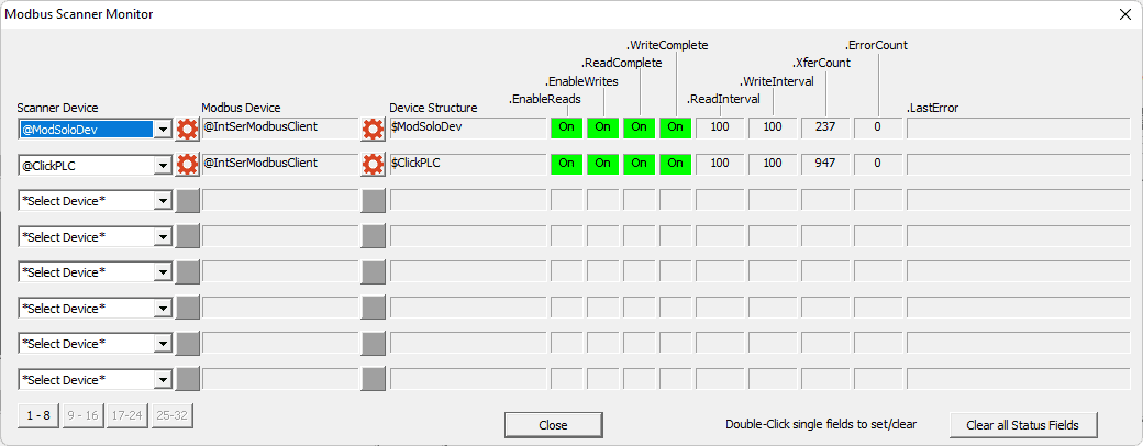
Monitoring the Modbus IO Scanner
Select Modbus Scanner Monitor from the main menu | Debug.
 We can quickly see our Modbus Scanner working.
 Using the Data View we can all up the registers that we specified to see the PV and SV of the Solo temperature controller as well as the Click PLC.
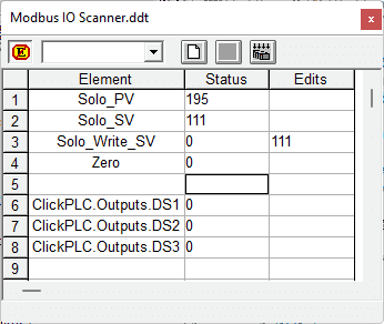
Change the value in V2. This will automatically send the new SV of the Solo. The Click PLC address DS3 or using the Solo unit itself will also change the SV.
Watch the video below to see how to communicate using a Modbus IO scanner profile and use ladder logic to set the Solo Process Temperature Controller SV (Set Value).
Download the BRX Do-More and Click PLC programs here.
BRX Series PLC from Automation Direct – Power to deliver
Overview Link (Configure and purchase a system)
Manuals and Product Inserts (Installation and Setup Instruction)
Do-More Designer Software (Free Download Link) – The software will contain all of the instruction sets and help files for the BRX Series PLC.
Watch on YouTube: BRX Do-More PLC Using Modbus IO Scanner Profile
If you have any questions or need further information please contact me.
Thank you,
Garry
If you’re like most of my readers, you’re committed to learning about technology. Numbering systems used in PLCs are not difficult to learn and understand. We will walk through the numbering systems used in PLCs. This includes Bits, Decimal, Hexadecimal, ASCII, and Floating Point. To get this free article, subscribe to my free email newsletter.
Use the information to inform other people how numbering systems work. Sign up now. The ‘Robust Data Logging for Free’ eBook is also available as a free download. The link is included when you subscribe to ACC Automation.