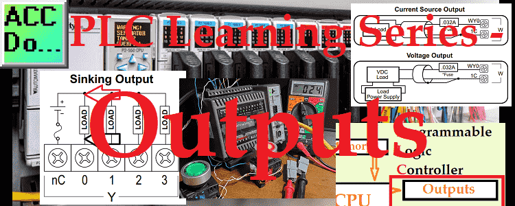
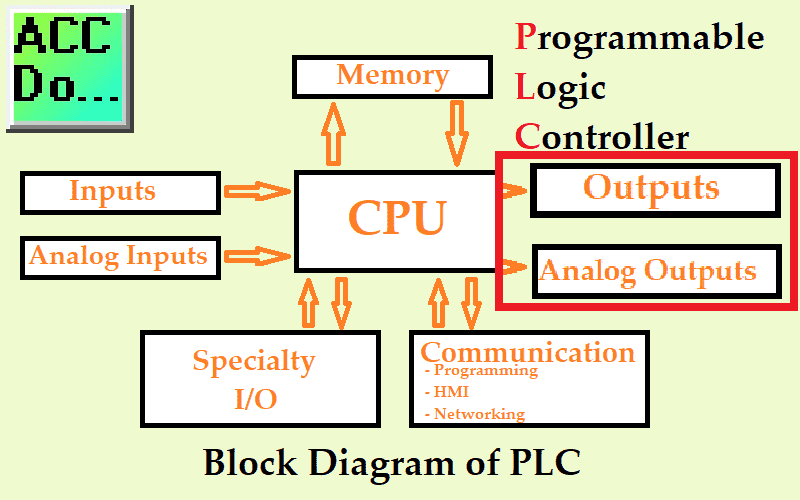
PLC outputs are the next component of our PLC block diagram. The PLC program will control the outputs of the PLC. Controlling outputs is one way to get the inputs to change. We will be looking at digital and analog outputs that can be wired to the programmable logic controller.
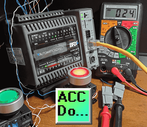
PLC troubleshooting outputs will also be discussed. This will be done using a multimeter measuring the voltage at the PLC output and across the discrete output load. We will also measure and control analog signal output. Let’s get started.
Previously in this PLC Learning Series:
PLC Training Series – Tutorial for Everyone – Video
What are PLC Inputs? – Video
What are PLC Outputs?
PLC output usually refers to the physical devices connected to the programmable logic controller. Outputs are generally isolated from the CPU of the PLC through light. This isolation is the reason that if the output is destroyed, the PLC can still function. Usually, the output can be corrected, and a new output card can be placed on the PLC. Alternatively, the output can be corrected, and the PLC output can be programmed for another output address.
Note: You must refer to the specification from the manufacturer to determine how the outputs are protected.
These output devices allow the PLC to perform an action and control the inputs if feedback is from the output.
Physical outputs are what we will be looking to wire and understand. Lights, relays, solenoids, and speed references, are just a few examples of PLC outputs. Operator outputs through a human-machine interface (HMI) are also a form of PLC outputs that we will discuss later.
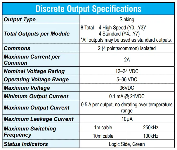
Here are the specifications for the discrete outputs on our BRX Do-More PLC.
BX-DM1E-18ED13
Technical Specifications
You will see that we have eight discrete outputs with four input points per common.
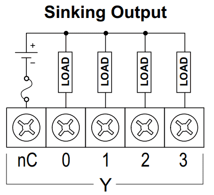
The power supply per common is sinking (0VDC on the common). Each of the individual inputs completes its circuit. The output point to the common is a switch that can turn a load on the output on or off.
Discrete vs. Analog PLC Outputs
Discrete and analog PLC outputs are the usual method for specifying the PLC. The physical number of discrete outputs and analog outputs helps to determine the PLC’s size or the PLC’s ability.
Discrete or Digital outputs refer to an on/off or I/0 type of input. They will only have these two states.
Analog outputs will refer to a range expressed in the units specified for the device. An example would be a voltage reference for a variable frequency drive (VFD). A voltage can be sent to the drive to determine the operating speed (frequency). These analog outputs can usually be scaled. This will aid in the readability of the program. In our example, we can scale a 0 to 60 hertz (Hz) variable to represent a 0 to 10 VDC signal.
Watch the video below to see this scaling in action.
Discrete PLC Outputs
Discrete digital outputs, as mentioned before, is either on or off. Think of these as switches that will control the load.
If the PLC output is off, the switch is open. The electrical circuit is not complete, so the load is not energized. If the PLC output is on, the switch is closed. The electrical circuit is complete, so the load is energized.
It is essential to look at the switch capacity to ensure the load will not exceed this limit.
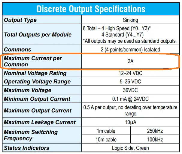
Looking at the specifications, we can have a maximum of 2 amps of current per common. So the current draw for each output load on that common must be less than two amps.

Here are the specifications for the LED output lamps on our push buttons. Each LED will draw 11 milliamps. Since we have two LED lights on the same common, 22 milliamps will be the current consumption. This is well below the 2 amp (2000 milliamp) maximum load.
Watch the video below to see the push buttons in action connected to our PLC.
What do Sinking and Sourcing mean?
Sourcing and sinking refer to direct current (DC) and the wiring of the PLC. The PLC output acts as a switch for the output point circuit. If the common for the output point is +VDC, then the load is sourcing. This is also referred to as plus or positive switching. If the common for the output is 0VDC, then the load is sinking. This is also referred to as minus or negative switching. Looking at the reference of the PLC output point will determine sinking or sourcing. The common practice is to have the entire PLC sourcing or sinking for both the inputs and outputs. Since the outputs are usually fixed, this will dictate how the inputs should be wired.

Looking at our outputs, you can see that the common for the output is 0VDC. These are sinking outputs.
Note: Always check the manufacturer’s specifications before wiring the PLC
Troubleshooting Digital Outputs on the PLC
PLC troubleshooting becomes easy when you think of every output as an individual circuit. If we measure the voltage across the PLC output point (switch), we can quickly determine if the circuit is correct.
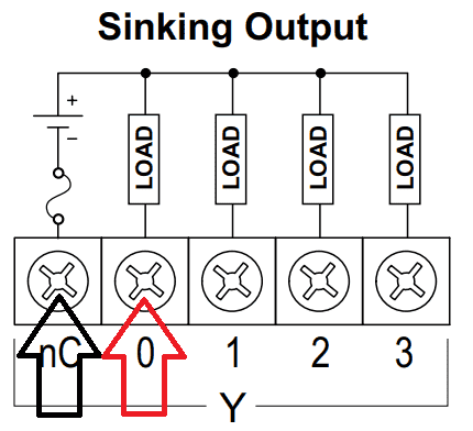
If the output point is off, then we should see the full voltage potential across the switch. Zero voltage will be seen when the output point is on. This is because we no longer have a potential voltage across the output. It becomes, in essence, a direct wire.
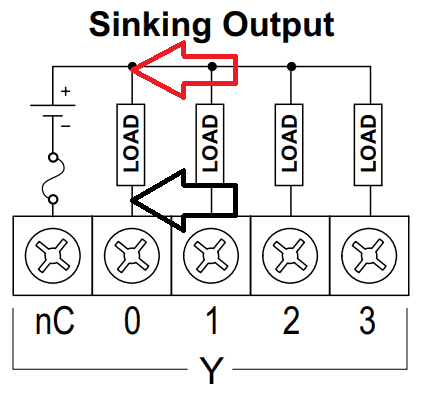
Measurement across the load of the PLC is a more common approach. If the output point is off, then we see no voltage across the load. (0VDC) We will see full voltage across the load if the output point is on. (+VDC) The load will then be active or on.
Watch the video below to see a demonstration of this using a multimeter.
Analog PLC Output
An analog output converts a digital value stored and processed in the PLC into a voltage or current level. Standard industrial voltages are 0-10 or 1-5 volts DC or 0-20 or 4-20 mA current.
Analog voltage outputs are the most common. I believe this to be true because they are easy to wire and test with a multimeter. 0 – 10 VDC analog is the most popular but has the most significant risk of being influenced by noise.
Analog current outputs are better for long-distance runs and less noise-prone. You can also place a 250-ohm resistor on an analog 4 – 20 mA current sensor and get a voltage output of 1 – 5 VDC. Using ohm’s law, you can see how this works.
Note: Always refer to the manufactures specifications for the wiring diagrams for your analog output signal.
BX-DM1E-18ED13
Technical Specifications
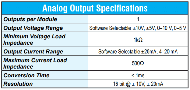
Here are the PLC specifications for an analog PLC output. Conversion time (update) will tell you how quickly the analog can be updated in the PLC. The maximum current resistance (Impedance) is 500 ohms. This will limit the current in the circuit. This can also be expressed as the minimum resistance of the circuit. See ohm’s law to determine the relationship between current, resistance, and voltage.
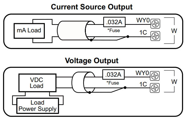
The wiring diagram will show both the analog current and voltage output.

You can select the analog output signal and scaling factors depending on the PLC used.
Watch the video below to see the analog output operating in our PLC. We will be measuring the voltage using a multimeter.
PLC Beginner’s Guide to PLC Programming
There are many different PLC manufacturers with other hardware and software. All of the programmable logic controllers have similar basic features. Here is how I would approach learning about basic PLCs.
Once you are familiar with the basics of the PLC, you will then learn specifics for the controller you will be programming.
This is the easiest way to learn about PLC programming.
Watch on YouTube: PLC Learning Series – What are Outputs?
If you have any questions or need further information, please contact me.
Thank you,
Garry
If you’re like most of my readers, you’re committed to learning about technology. Numbering systems used in PLCs are not challenging to learn and understand. We will walk through the numbering systems used in PLCs. This includes Bits, Decimals, Hexadecimal, ASCII, and Floating Points.
To get this free article, subscribe to my free email newsletter.
Use the information to inform other people how numbering systems work. Sign up now.
The ‘Robust Data Logging for Free’ eBook is also available as a free download. The link is included when you subscribe to ACC Automation.

