
We will apply the five steps to PLC Program development to our following programming example of a process mixer.
The process mixer will be programmed using ladder logic. We will discuss each step of the PLC program development.
1 – Define the task:
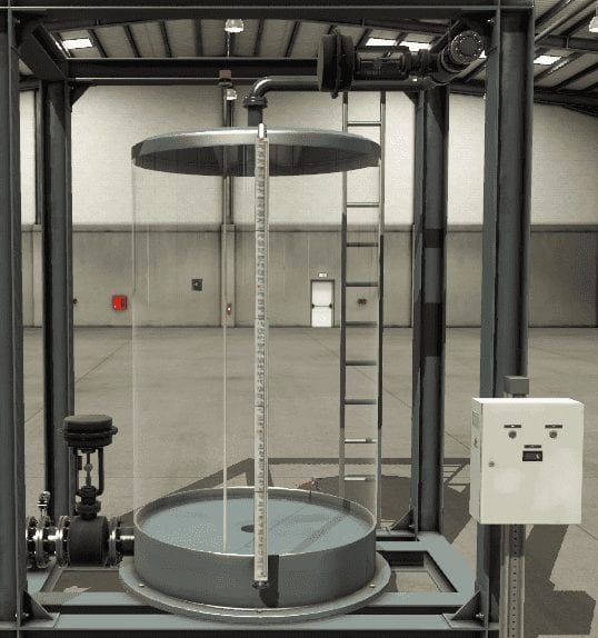
How does the process mixer work?

A normally open start and normally closed stop pushbuttons are used to start and stop the process. When the start button is pressed, solenoid A energizes to begin filling the tank. As the tank fills, the empty level sensor switch closes. When the tank is complete, the full-level sensor switch closes. Solenoid A is de-energized. The mixer motor starts and runs for 3 minutes to mix the liquid. When the agitate motor stops, solenoid B is energized to empty the tank. The empty sensor switch opens to de-energize solenoid B when the tank is empty. The start button is pressed to repeat the sequence.
2 – Define the Inputs and Outputs:
What sensors will be used in the PLC program?
Inputs:
Start Pushbutton – Normally Open – On/Off
Stop Pushbutton – Normally Closed – On/Off
Empty Sensor Switch – On/Off
Full Sensor Switch – On/Off
Timer 3 minutes done bit – On/Off (Internal)
Outputs:
Mixer Motor – On/Off
Solenoid A – Fill – On/Off
Solenoid B – Empty – On/Off
Timer 3 minutes – (Internal)
3 – Develop a logical sequence of operations:
How is the PLC example program solve the logic?
A flow chart or sequence table is used to understand the process entirely. It will also prompt questions like the following.
What happens when electrical power and/or pneumatic air is lost? What happens when the input / output devices fail? Do we need redundancy?
Knowing all of these answers upfront is vital in developing the PLC program. This is the step where you can save a lot of work by understanding everything about the operation. It will help prevent you from continuously re-writing the PLC logic.

4 – Develop the PLC program
I am writing the PLC sample ladder logic program for the process mixer.
Since we must continue the sequence when the power goes off, memory retentive locations in the PLC must be used. In our example, we will use the ‘V Memory’ areas.
The first thing in our program is to control the start and stop functions. This is done through a latching circuit. From the sequence table, we know that we need to have the timer done and the empty sensor off to reset the sequence.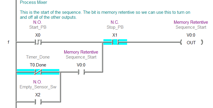
The filling of the tank is done through Solenoid A. It is turned on by the start signal and off by the full sensor switch. (Sequence Table) You will notice that we have a memory retentive output and the actual output to activate the solenoid.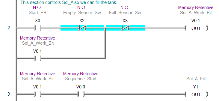
The retentive memory timer will start timing when we have the start sequence signal and when the empty and fill sensors are on. The timer will reset when the empty and fill sensors are off. The mixing motor will be on when the timer is timing and when the timer is not done.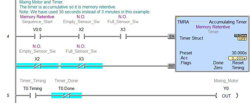
Solenoid B turns on to empty the tank when the timer is done and the full and empty sensors are on. It will reset when the empty sensor switch goes off.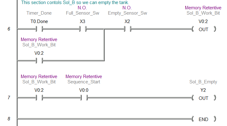
5- Test the program
Simulate the PLC program of the Process Mixer.
Test the program under many conditions. Check to see what happens when power is removed.
Using this five-step program development technique will shorten your programming time. The result will be a better-defined logic and easier to understand the program because it has the logic flow chart or sequence table within the documentation.
Watch on YouTube: PLC Programming Example – Process Mixer
Testing of the program is essential and should be done in various ways. Factory IO provides a 3D simulation of the process. Factory IO provides a straightforward method of seeing your program in action before you wire your application.
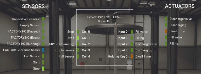
We will be using the BRX PLC Modbus TCP Server (Slave). Factory IO will be the Modbus TCP Client (Master). When the tank fills up, we will start a dwell time instead of the mixer time for the simulation.
Here is the mapping of the inputs and outputs using Factory IO.
Factory IO Website is at the following URL:
https://factoryio.com/
The documentation is well done. Start at the ‘Getting Started’ at the following URL:
https://factoryio.com/docs/
You can download the PLC program and Factory IO scene here.
Watch the following video to see this simulation in action.
Watch on YouTube: Process Mixer Test Simulation
https://youtu.be/vJpGJQ8MwCk.
If you have any questions or need further information, please get in touch with me.
Thank you,
Garry
If you’re like most of my readers, you’re committed to learning about technology. Numbering systems used in PLCs are not challenging to learn and understand. We will walk through the numbering systems used in PLCs. This includes Bits, Decimals, Hexadecimal, ASCII, and Floating Points.
To get this free article, subscribe to my free email newsletter.
Use the information to inform other people how numbering systems work. Sign up now.

The ‘Robust Data Logging for Free’ eBook is also available for free download. The link is included when you subscribe to ACC Automation.
Can you give me the 3D simulator program?
Hi Sufian,
You can download the software at the following address:
https://factoryio.com/
The trial version will give you the Ultimate Edition will all of the features for 30 days.
Regards,
Garry
hi
i want to implement this project.
how can i do this?
first of all what software shpuld be installed?
then how to setup?
how to implement that ladder logic and where i can implemet that?
i am so confused right now.
can you guide me every step in detail.
thanks in advance
Hi Sanika Divekar,
PLC Beginner’s Series with Free Simulator – Do-More Designer
Look for this title on the following webpage.
https://accautomation.ca/programming/plc-beginners-guide/
This will take you through the steps on this software.
Regards,
Garry