
We apply the five steps of PLC development to a plc shift register example. This PLC programming example will use a shift register to reject a product on a conveyor.
When programming a PLC, you need to track what has previously happened. Shift registers allow you to do just that. We will look at a PLC basic tutorial on a conveyor belt and reject station. Following the five steps to program development, this PLC programming example should fully explain the function of shift registers. Ladder logic will be our PLC programming language.
We will use the Do-more Designer software, which comes with a simulator. This fully functional program is offered free of charge at automation direct.
Define the task:
Shift Register – Conveyor Reject
What has to happen?
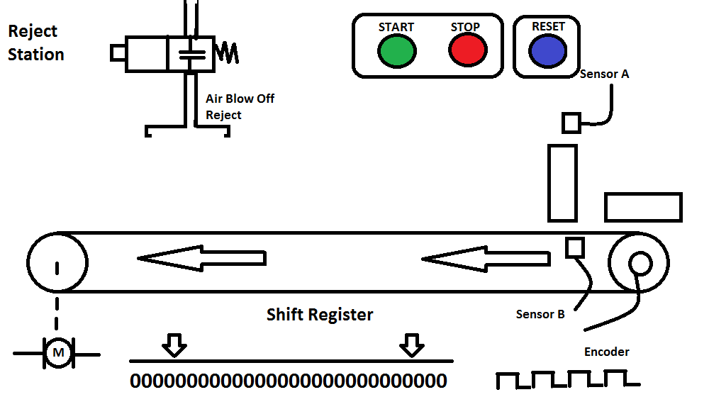
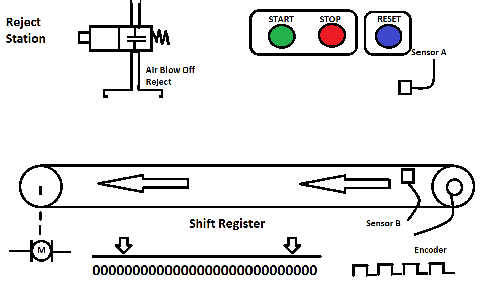
A start pushbutton (NO) is used to start the conveyor, and a stop pushbutton (NC) is used to stop it. Sensor B detects a product on the conveyor belt, and sensor A will see if it is too large and needs to be rejected. The product is tracked along the conveyor belt, and when under the reject station, the Reject Blow Off will expel the wrong product. The product is randomly placed on the conveyor belt, so an incremental encoder tracks the conveyor movement. The reset pushbutton (NO) will signal that all of the product on the conveyor has been removed between the sensors and reject the blow-off.
Define the Inputs and Outputs:
PLC Connections for the Shift Register Conveyor Example
Inputs: Start Switch – On/Off (Normally Open) – NO Stop Switch – On/Off (Normally Closed) – NC Reset Switch – On/Off – NO Motor Encoder – On/Off – This will give a discrete signal when the conveyor is moving. It picks up the movement of the freewheel. Sensor A (Part Reject) – On/Off – NO Sensor B (Part Present) – On/Off – NO
Outputs: Motor – On/Off (Conveyor Run) Air Blow Off – On/Off (Reject)

Develop a logical sequence of operations:
PLC Logic for Shift Register Conveyor Reject
Fully understanding the logic before starting to program can save you time and frustration.
Sequence Table: The following is a sequence table for our conveyor reject application.
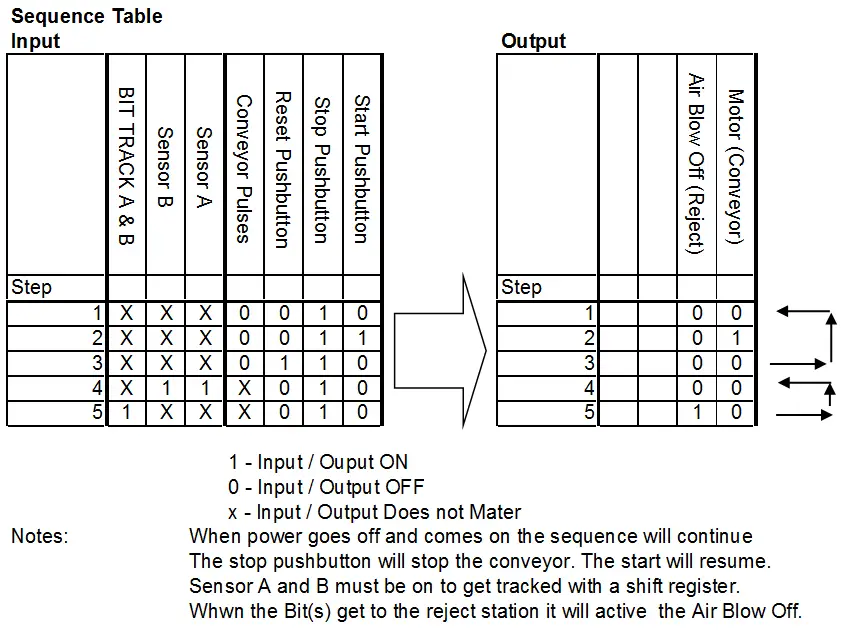
It is a simple sequence table but clarifies the following: The sequence will continue when the power goes off and comes on. This means that the shift sequencer must be memory retentive. Sensors A and B must be on to get tracked with a shift register.
Shift Registers: The Shift Register (SR) instruction shifts data through a predefined number of BIT locations. These BIT locations can be a range of BITs, a single Word or DWord, or a range of Words or DWords. The instruction has three inputs. Data, Clock, and Reset. The data input will load the beginning bit with a ‘1’ if it is on or a ‘0’ if not. The clock input is used to shift the data through the shift register. In our example, we will use the conveyor’s encoder to track the reject container. So each pulse of the clock represents a distance on the conveyor. The last input is the reset. It will place ‘0’ in all the bits within the shift register.

Develop the PLC program:
Conveyor Reject
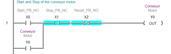
Start and stop the conveyor motor.
Shift register to track the rejected parts. This will move the bits with each pulse of the encoder. Note that the ‘V’ memory is used because it is memory retentive.
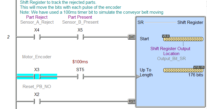
This will look at the bit in front of the reject station. We can measure and count off the length (conveyor) and then determine the bit location at the reject location.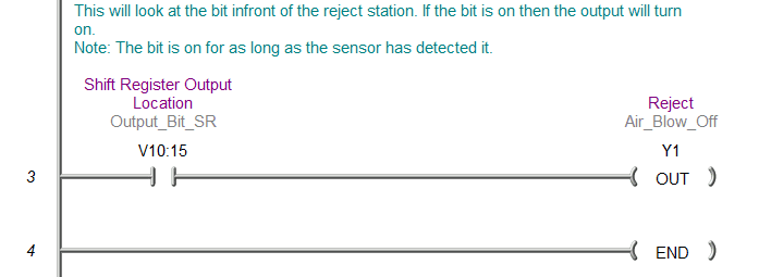
Test the PLC program:
Shift Register Conveyor Reject
Test the program with a simulator or actual machine. Make modifications as necessary. Remember to follow up after a time frame to see if any problems arise that need to be addressed with the program.
Notes: Sometimes, you can use multiple shift registers in your program. This can be helpful if you want to track the container and the rejects. You could also use a bit shift right (BSR) and bit shift left instructions (BSR) to do the same thing as we did with the shift register instruction. The Do-more PLC rotates left (ROTL) and rotates right (ROTR) instructions. Always check the instruction set of the controller you are working with before starting the program.
Watch on YouTube: PLC Programming Example – Shift Register (Conveyor Reject)
Additional information on shift registers can be seen at the following URL:
https://accautomation.ca/plc-programming-example-sorting-station-shift-register/
This PLC programming example will sort colored tags into three different exits. The 3D simulation will use three different shift registers to trigger when to direct the correct color tag.
Watch the sequence of operation video below.
Watch on YouTube: PLC Programming Example – Sorting Station Testing
If you have any questions or need further information, please get in touch with me.
Thank you,
Garry
If you’re like most of my readers, you’re committed to learning about technology. Numbering systems used in PLCs are not challenging to learn and understand. We will walk through the numbering systems used in PLCs. This includes Bits, Decimals, Hexadecimal, ASCII, and Floating Points.
To get this free article, subscribe to my free email newsletter.
Use the information to inform other people how numbering systems work. Sign up now.

The ‘Robust Data Logging for Free’ eBook is also available for free download. The link is included when you subscribe to ACC Automation.
There is no shift register instruction in the step7-s300 ?
Hi Sufian,
The Siemens S7-300 does not have a shift register like the one mentioned above. However, it does have shift instructions.
https://cache.industry.siemens.com/dl/files/730/13206730/att_90770/v1/s7300_instruction_list_en-US.pdf
Please see page 92 for the shift instructions in the S7-300.
You would build the same type of instruction using a few instructions. The input would be to turn on the first bit of the output word that you want to shift.
The Clock bit would be the condition on the rung to shift the output word.
The reset would be a move instruction into the output word(s).
If you need the shift register longer then allow the most significant bit to then trigger the least significant bit of the next word to shift.
I hope this helps you out.
Regards,
Garry
Thank you
I do it in the same way