Invented in 1968 by Dick Morley, the programmable logic controller (PLC) is a simple rugged industrial computer. This free plc training series is designed for everyone to learn about these controllers. PLCs are constantly evolving and continue to be the best option for a variety of industrial automation applications.
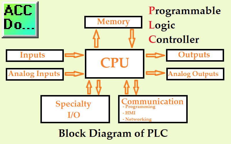
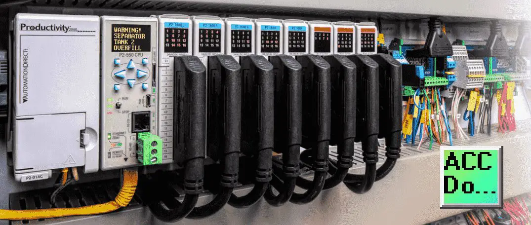
Even though the PLC is changing, core items remain the same. We will be discussing this in more depth for each of the components mentioned in the picture above. Let’s get started learning about PLCs.
Development of the Programmable Logic Controller – PLC
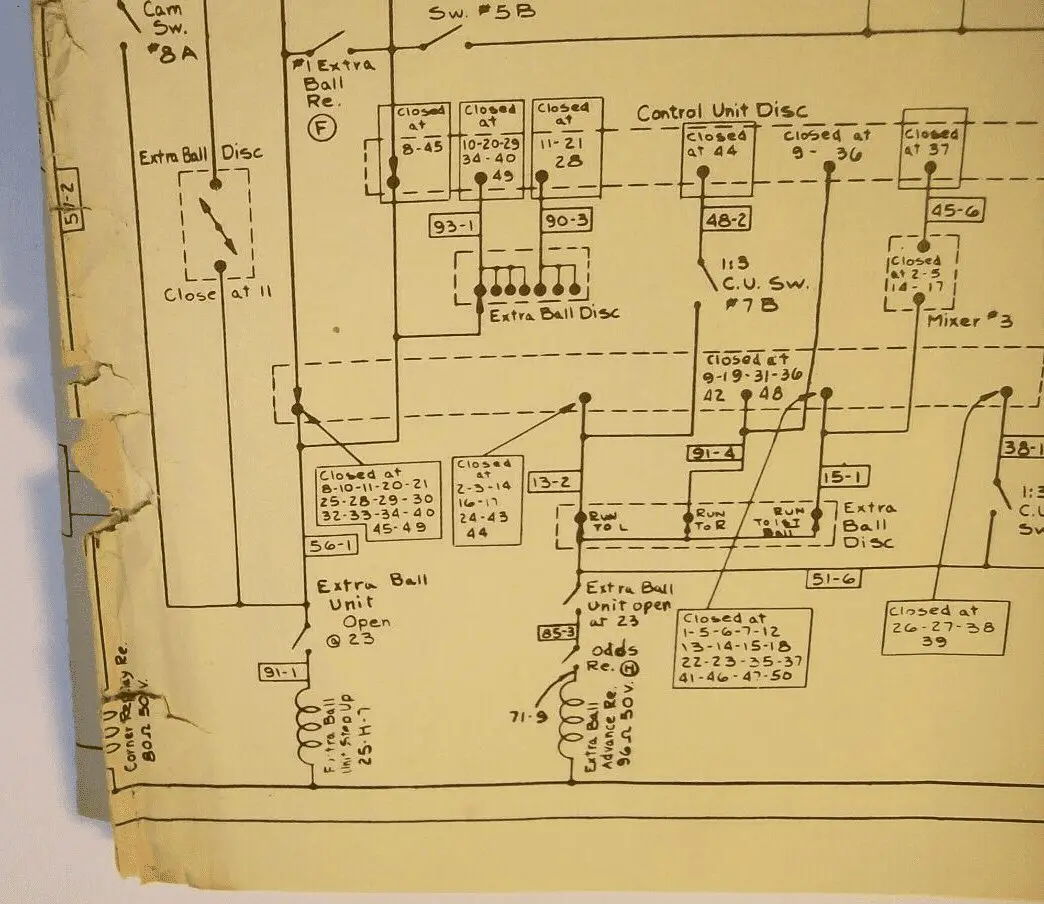
In the beginning, the PLC typically replaced relay circuits. Old panels consisted of general relays, timers, counters, latching relays, pushbuttons, indicator lights, etc.
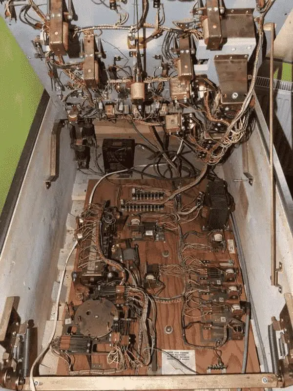
The picture is of a vintage pinball machine.
This was called hard wiring because everything had to be physically wired to determine the logic. Imagine what you would have to do if the ball hit the bumper and you want a different light to light up. How about different points for the number of times the bumper was hit? Rewiring was a common problem based on performance or changing processes.
The PLC simplified this situation.
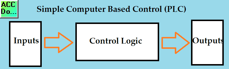
The PLC is simplistic in its design. The inputs are wired to individual input points and outputs are wired to individual output points. Relationships between the inputs and outputs were controlled with a program that solved the logic. This program could be easily changed to account for changes required in the operation.
Schematics to Ladder Logic – PLC
The schematic drawings of the old hard-wired panel were the only mechanism to troubleshoot and maintain the machine.
Schematics are still used today to show the wiring of the emergency stop, inputs, and outputs to the PLC.
Ladder logic was introduced for logic programming. This language was chosen to keep things simple for the technicians and engineers who grew up with relay logic.
IEC 61131-3 introduced other programming languages for the programmable controller but ladder logic is still to this day the leading way to program the PLC. The large established base of PLCs is programmed in ladder logic and the supporting engineers, technicians, electricians, and maintenance personal prefer this simple programming language.
Reading Ladder Logic – PLC
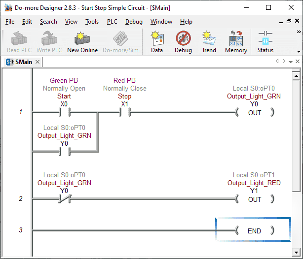
The PLC ladder logic is read from left to right, top to bottom. So just like our reading the ladder logic is solved. The output or logic from the previous rung is available for the next rung to use. We will discuss this at a later time.
Outputs in the logic are located on the right-hand side of the ladder diagram. Inputs are located on the left-hand side of the ladder diagram. When the input logic is true (on or 1) this will turn the corresponding output logic true. (on or 1)
When the end of the ladder is reached, the PLC will update the physical inputs and outputs, check communication, check memory, etc. It will then solve the PLC ladder logic again.
One cycle of this routine is called a PLC scan. Depending on the PLC, scan times vary from different manufactures.
A 10 millisecond scan time will scan your PLC ladder logic 100 times per second or 100 hertz. (100Hz)
(1s / 0.010 = 100 times per second)
A 1 millisecond scan time will scan your PLC ladder logic 1000 times per second or 1 kilohertz. (1Khz)
(1s / 0.001 = 1000 time per second)
Monitoring Ladder Logic – PLC
One of the advantages of the PLC is the ability to visually see what is happening in the logic of the controller. This is referred to as online monitoring. Troubleshooting and commissioning of new systems are greatly reduced by using this important feature of the PLC. If the input or output is logically true (on or 1) then the input or output is highlighted.
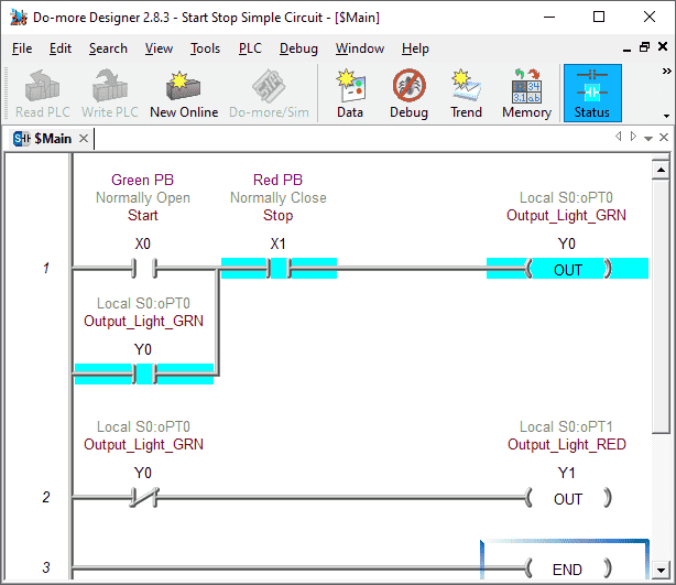
In this example, you can see that the output is on. This output is also used as an input to ensure that the output remains on.
On-line Edit Ladder Logic – PLC
On-line programming or edit of the ladder logic in the PLC is something that is standard with most modern PLC today. This will allow you to change the ladder logic while the machine is still scanning and solving the logic.
On-line editing will hold the scan, insert the new code and then release the scan. This happens all within a fraction of time. Once again troubleshooting and commissioning of systems rely on this important feature of the PLC.
Specialty Devices – PLC
The PLC will deal with specialty devices like motion control and human-machine interfaces in several different ways. Every manufacturer will have a slightly different method of handling these devices. Specially designed PLCs will have these features built into the controller. Some will have dedicated devices and communication protocols that protect their market share. Others will use common industrial protocols to communicate. One of the methods used more recently is the ability to incorporate the same database tags between the PLC and any of the specialty devices. This aids in the elimination of errors and time to do this task. We will discuss this in future posts.
Future of the PLC in Industrial Automation
The PLC has remarkable staying power. There have been attempts to use higher-level computer systems but this creates problems when the logic must run 24 hours a day 7 days a week with a constant scan time. The PLC will be around for a long time but as mentioned before, it will be constantly changing.
Modern PLCs include many communication ports to support multiple protocols. Standardized protocols like MQTT make a connection to the manufacturing plant’s Enterprise Resource Planning (ERP) system easier than ever before. This will allow Overall Equipment Effectiveness (OEE) to improve significantly. This is basically what is meant by Industry 4.0, Internet of Things (IoT), or the Industrial Internet of Things. (IIoT)
Future PLCs will include greater programming flexibility, ease, and scalability. Physically the PLC will become smaller, have more memory, and have industrial plug and play options.
Watch the video below to see the basics of the PLC.
PLC Beginner’s Guide to PLC Programming
There are many different PLC manufacturers with different hardware and software. All of the programmable logic controllers have similar basic features. Here is how I would approach learning about basic PLCs.
Once you are familiar with the basics of the PLC you would then learn specifics for the controller that you will be programming.
This is the easiest way to learn about PLC programming.
Watch on YouTube: PLC Training Series – Tutorial for Everyone
If you have any questions or need further information please contact me.
Thank you,
Garry
If you’re like most of my readers, you’re committed to learning about technology. Numbering systems used in PLC’s are not difficult to learn and understand. We will walk through the numbering systems used in PLCs. This includes Bits, Decimal, Hexadecimal, ASCII and Floating Point.
To get this free article, subscribe to my free email newsletter.
Use the information to inform other people how numbering systems work. Sign up now.

The ‘Robust Data Logging for Free’ eBook is also available as a free download. The link is included when you subscribe to ACC Automation.