Discover the inner workings of PLC logic in scan cycles and unlock a deeper understanding of industrial automation. We delve into the world of Programmable Logic Controllers, exploring the intricacies of scan cycles and how they execute PLC logic. 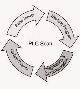
Learn how PLCs process inputs, execute programs, and update outputs in a continuous cycle, and gain insights into the programming and configuration of PLCs. Whether you’re an experienced engineer or just starting out in the field, this video will provide a comprehensive overview of PLC logic in scan cycles, helping you to improve your skills and knowledge in industrial automation.
Surprising Fact about PLC Scan Cycle
When a PLC scans a rung with multiple series contacts, it stops evaluating the rung as soon as it finds a FALSE condition.
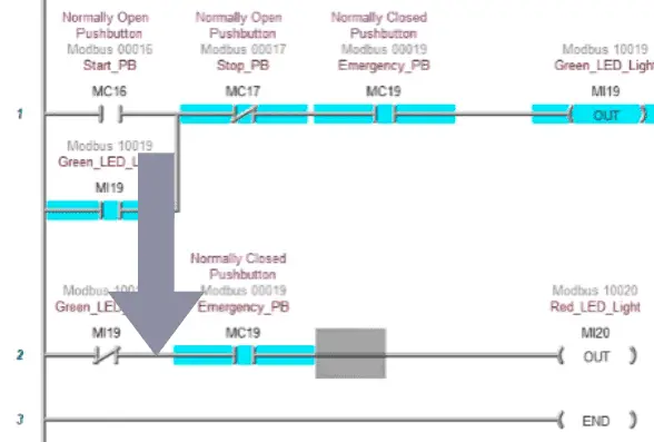
This means that if you have a series of five contacts and the first one is already FALSE, the PLC will not even check the other four. Therefore, by placing the contacts that are most likely to be FALSE at the beginning of the rung, you can save valuable microseconds of scan time on every single scan, which adds up to a surprising amount of efficiency over time.
PLC Logic and Its Importance in Automation
At the heart of PLC programming is the execution of the PLC logic. The running of the PLC controller is also known as the scan. Scan and scan time are essential to understand in automation. Scan cycles run cyclically. This means that they repeat continuously at a very high speed, which allows for real-time control of your automation project.
Common Misconceptions about PLC Scan Cycle
There are many common misconceptions about what happens during PLC scan cycles. The PLC sees all inputs and updates all outputs simultaneously. Scan time is always constant, or all inputs and outputs are updated in the same order as they appear in the program. PLC scan cycles are critical to understand for responsiveness and timing, troubleshooting, and program optimization.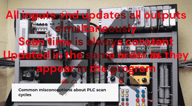
Stages of a PLC Scan Cycle
The concept of a scan cycle is central to how PLC logic operates. A PLC doesn’t process its logic all at once; it does so in a continuous loop, or “scan.” Each scan cycle consists of three primary steps:
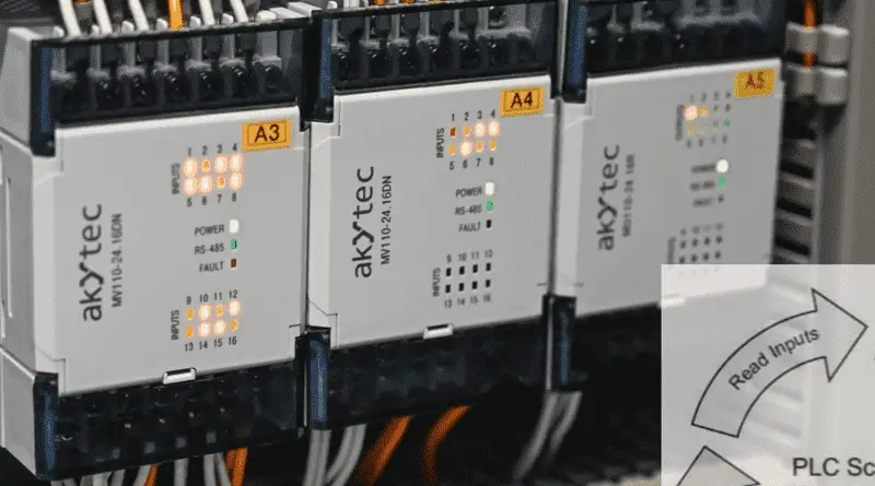
1. Read Inputs: The PLC checks the status of all its input devices. It first reads all inputs and stores their status in an Input Image Table. If an input changes during this time, the input image table will not update until the next scan of the input.
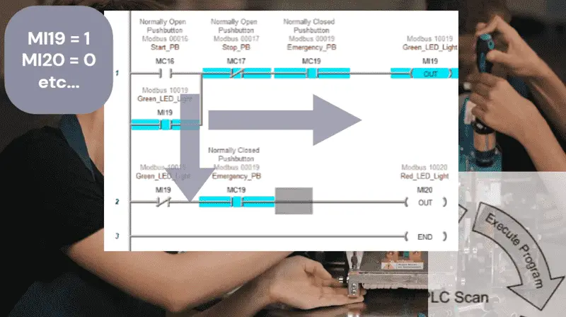
2. Execute Logic: It runs the user-defined program from the beginning to the end, using the input image table data it just gathered. If we look at ladder logic, the logic is solved left to right, top to bottom. The Output Image Table is updated as the logic is solved. These changes are available for the next rung of ladder logic to use. As mentioned, when solving the logic, if any of the series inputs result in being negative, then the output is immediately updated in the output image table. This execution creates the fastest possible time to update, and so the scan is not normally constant.
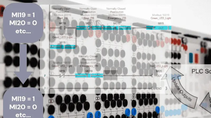
3. Update Outputs: It writes the new status to all the output devices based on the Output Image Table results of the program execution.
This entire process repeats continuously and at very high speeds, which allows for real-time control of the automation system. The PLC reads all inputs before executing the program logic, and then updates all outputs after the logic is complete. The order of instructions within the program itself can affect the internal logic, but the physical I/O is handled in a set sequence during each scan.
Scan Cycle Optimization
The PLC scan cycle is a sequential process. It first reads all inputs and stores their status in an Input Image Table. It then executes the program logic using the data from this table, not the live inputs. Finally, it updates the physical outputs based on the results of the program execution. This means there is a slight delay between a change in a physical input and the corresponding change in a physical output.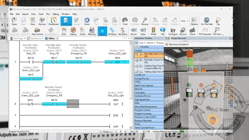
There are many different PLC manufacturers with their own hardware and software. All programmable logic controllers share similar basic features. To learn how to approach learning about basic PLCs, click here. Click here to learn more about how PLC Simulators can be used to help your programming skills.
Watch on YouTube: What is PLC Logic in Scan Cycles REALLY Doing?
There are many different PLC manufacturers with other hardware and software. All of the programmable logic controllers have similar basic features. Here is how I would approach learning about basic PLCs.
Once you are familiar with the basics of the PLC, you will then learn specifics for the controller you will be programming.
This is the easiest way to learn about PLC programming.
Here are the controllers that we have covered or are covering at ACC Automation:
LS Electric XGB PLC Series
BRX Do-More Series (Do-More Designer Software + Simulator)
Productivity Series P1000 / P2000
Click PLC Series
Omron CP1H Series
Horner XL4 PLC Series
Arduino Opta PLC
The EasyPLC Software Suite is a comprehensive package that includes PLC, HMI, and machine simulator software. See below to receive 10% off this software. This PLC learning package includes the following:
Easy PLC – PLC Simulation will allow programming in Ladder, Grafcet, Logic Blocks, or Script.
HMI System – Easily create a visual human-machine interface (HMI)
Machine Simulator – A virtual 3D world with real-time graphics and physical properties. PLC programs can be tested using the EasyPLC or through other interfaces. (Modbus RTU, TCP, etc.)
Machine Simulator Lite – Designed to run on Android Devices.
Machine Simulator VR – Virtual Reality comes to life so you can test, train, or practice your PLC programming.
Purchase your copy of this learning package for less than $95 USD for a single computer installation or less than $110 USD to allow access on multiple computers.
Receive 10% off the investment by typing in ACC in the comment section when you order.
Learn PLC programming the easy way. Invest in yourself today.
Examples of PLC program development using the five steps.
Click PLC – Easy Transfer Line Programming – Video
Productivity PLC Simulator – Chain Conveyor MS – Video
Five Steps to PLC Program Development – Die Stamping
PLC Programming Example – Process Mixer
PLC Programming Example – Shift Register (Conveyor Reject)
PLC Programming Example – Paint Spraying
PLC Programming Example – Delay Starting of 7 Motors
PLC Programming Example – Pick and Place
PLC Programming Example – Sorting Station (Shift Register)
PLC Programming Example – Palletizer
If you have any questions or require additional information, please do not hesitate to contact me.
Thank you,
Garry
If you’re like most of my readers, you’re committed to learning about technology. Numbering systems used in PLCs are relatively straightforward to understand. We will walk through the numbering systems used in PLCs. This includes Bits, Decimals, Hexadecimal, ASCII, and Floating Points.
To get this free article, subscribe to my free email newsletter.
Use the information to educate others on how numbering systems work. Sign up now.

The ‘Robust Data Logging for Free’ eBook is also available as a free download. The link is included when you subscribe to ACC Automation.