
The Omron CP1H series of programmable logic controllers have a fixed input and output addressing system. Every PLC has its own way of addressing its inputs and outputs. We will be looking at how the CP1H series of controller addresses its inputs and outputs. Numbering systems used in this controller will also be looked at as well as addressing. Addressing can be direct or indirect. We will look at how this can be accomplished using examples in the CP1H controller.
Previously in this CP1H series, we have discussed:
System Hardware – Video
CX-Programmer – Video
Establish Communication – Video
Setting, Forcing and Online Editing – Video
Numbering System and Addressing – Video
CP1H Timers – Video
Counters – Video
Data Movement – Video
Compare Instructions – Video
Data Shift Instructions
– Video Part 1
– Video Part 2
Math Instructions – Video
Data Conversion – Video
Program Control Instructions – Video
Table Data Instructions – Video
Data Control Instructions – Video
AdvancedHMI Communication – Video
Omron Addressing Format – Omron Numbering Systems
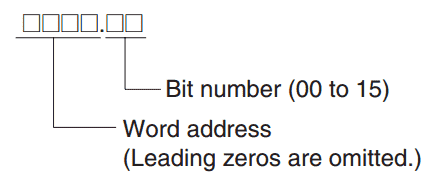
Let’s start with addressing format. All words in the Omron CP1H are made up of 16 bits. These bits are numbered 00 to 15 respectfully. To address a bit location we specify the word, followed by a period and then the bit number.
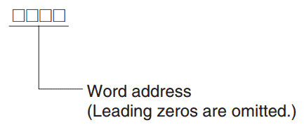
If we want to specify a word address then we leave out the period and bit information. The address is then understood to be all 16 bits.
Note: Instructions used in the controller will control how the memory area is to be interpreted. This could be Binary (Hex), BCD, Floating-Point, etc.
Please refer to the following post for information on numbering systems used in PLC systems.
What Everybody Ought to Know about PLC (Programmable Logic Controller) Numbering Systems
There is also a good summary of numbering systems in the following manual in section ‘1-1-6 Data Formats’.
W451 – SYSMAC CP Series CP1H CPU Unit Programming Manual
Prefix Symbols – Omron Numbering Systems
The Omron CP1H can determine the type of numbering system to use depending on either the instruction being executed or the prefix in front of the number. Here if the list of prefix symbols and the meaning for all 16 or 32 bit constants:
# – Unsigned binary – Range #0000 to #FFFF, #00000000 to #FFFFFFFF
+/- – Signed decimal – Range -32768 to +32767, -2147483648 to +2147483647
& – Unsigned decimal – Range – &0 to &65535, &0 to &429467295
# – BCD (Binary Coded Decimal) – Range – #0000 to #9999, #00000000 to #99999999
Memory Areas – Omron Numbering Systems
The CP1H has several memory areas that are pre-assigned in the PLC. These areas are identified in the address by the letter(s) before the word address.
Example:
Holding Area first word is addressed H0
Holding Area first word, first bit is addressed H0.00
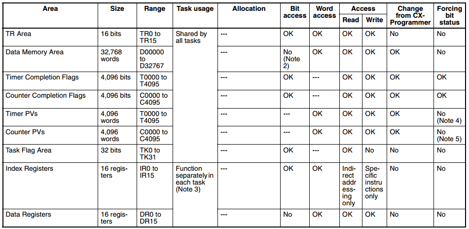
Here is a list of the memory areas in the CP1H controller.
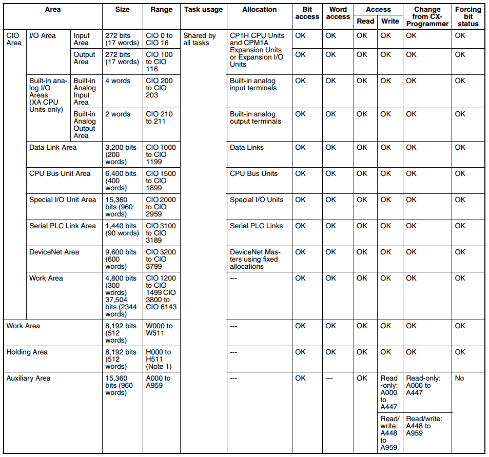
Note: CIO (Core Inputs Outputs) do not have a letter in front of the word address. This is understood to be part of the CIO area.
Example: 100.00 is the first output word bit 0.
Note: Leading zeros are omitted for the word address.
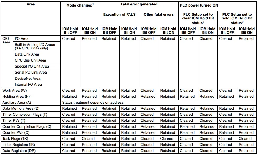
The above charts give an overview of the memory areas. These bits and words can be used in your program logic. You use these individual areas depending on what you need to accomplish. Example: If you need the bit information to be remembered in a power outage then use the Holding Register area.
The following chart explains what is memory retentive and non-memory retentive.
Indirect addressing – Omron Numbering Systems
Indirect addressing is the ability to get or send information via a pointer. The CP1H can use the DM or CIO areas for indirect addressing. Let’s look at a few ways that this PLC can address indirectly.
Note: Bits 21.00 to 21.06 are internal bits so we can trigger when our examples happen. See the YouTube video below to see this in action.
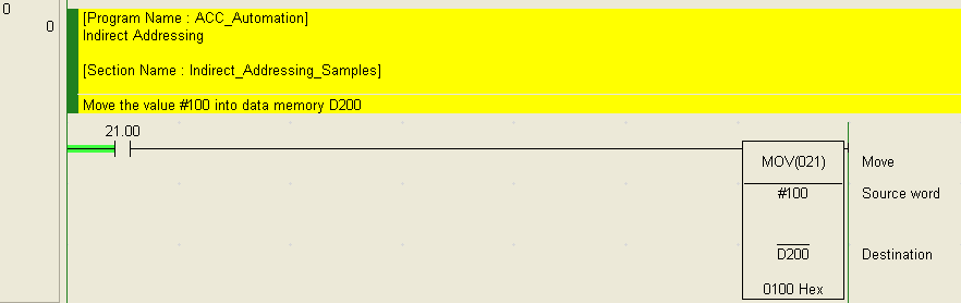
Moving the value #100 into data memory D200 will set up the register as a pointer.
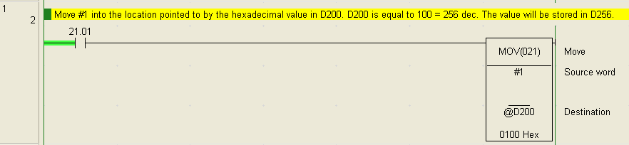
Move #1 into the location pointed to by the hexadecimal value in D200. D200 contains the number #100 which is equivalent to 256 decimal. The value will be stored in D256.
Note: The @ sign in front of the data memory address indicates binary indirect move.
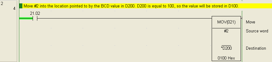
Move #2 into the location pointed to by the BCD value in D200. D200 contains the number #100. The value will be stored in D100.
Note: The * sign in front of the data memory address indicates BCD indirect move.
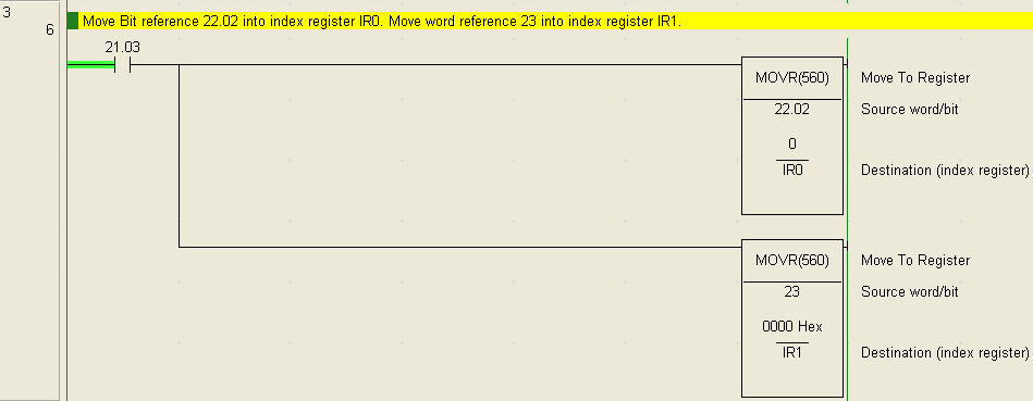
We now move bit reference 22.02 into index register IR0. A word reference is moved into index register IR1. Index Registers (IR) and Data Registers (DR) are used for indirect addressing of the CIO area.
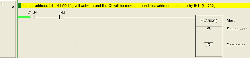
Bit ,IR0 is addressed indirectly. This will turn on when the bit in ,IR0 (CIO 22.02) is turned on. The #3 will be moved indirectly into the address pointed to by ,IR1 (CIO 23).
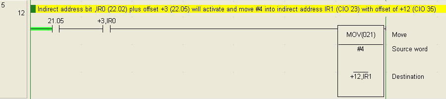
Offsets can be added to the indirect address. This includes the bits as well as the words. +3,IR0 input refers to ,IR0 (CIO 22.02) plus offset +3 (CIO 22.05).
+12,IR1 means that we will add 12 to the location in ,IR1 (CIO 23). The value will be placed in CIO 23 + 12 = 35.
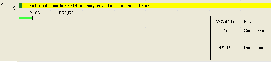
Indirect offsets can also be specified by using the data registers. This can be done again with both the bit and word level. It works similar to the specified offset but the value comes from the DR register specified.
CX programmer can help us out in understanding the memory areas in the PLC. If you look in the project tree you will see Memory. This is the memory available in the controller specified. (CP1H)
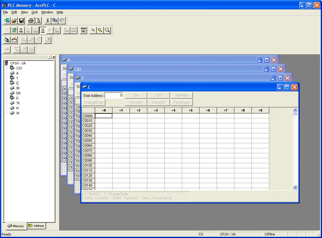
This will quickly tell you the size of the area. You can also go online and monitor this area.
See addressing and numbering systems in the CP1H PLC by watching the YouTube video below.
The following is a list of manuals associated with the CP1H programmable logic controller. See the descriptions for each of these manuals in the first post: Omron CP1H System Hardware
W450 – SYSMAC CP Series CP1H CPU Unit Operation Manual
W451 – SYSMAC CP Series CP1H CPU Unit Programming Manual
W342 – SYSMAC CS/CJseries Communications Commands Reference Manual
W446 – SYSMAC CX-Programmer Ver. 6.1 Operation Manual
W447 – SYSMAC CX-Programmer Ver. 6.1 Operation Manual Function Blocks
W444 – CX-One FA Integrated Tool Package Setup Manual
W445 – CX-Integrator Operation Manual
W344 – CX-Protocol Operation Manual
You can download the PLC program as discussed above here.
Next time we will look at timers in the Omron CP1H PLC.
Watch on YouTube : Omron CP1H Numbering Systems and Addressing
Watch on YouTube : Wiring (Testing) Analog PLC Input Omron CP1H
If you have any questions or need further information please contact me.
Thank you,
Garry
If you’re like most of my readers, you’re committed to learning about technology. Numbering systems used in PLC’s are not difficult to learn and understand. We will walk through the numbering systems used in PLCs. This includes Bits, Decimal, Hexadecimal, ASCII and Floating Point.
To get this free article, subscribe to my free email newsletter.
Use the information to inform other people how numbering systems work. Sign up now.

The ‘Robust Data Logging for Free’ eBook is also available as a free download. The link is included when you subscribe to ACC Automation.