We will apply the five steps to PLC program development to a pick and place robot example. The example will use a BRX PLC communicating to Factory IO (3D Software Simulator). Developing the PLC program is a process that can be clearly defined. In our series on the five steps to PLC program development, we have done some similar practical examples.
Five Steps to PLC Program Development – Press
PLC Programming Examples:
– Process Mixer
– Shift Register (Conveyor Reject)
– Paint Spraying
– Delay Starting of 7 Motors
Define the task: (1) – Pick and Place Programming Example
Watch the sequence of operation video below.
Watch on YouTube : PLC Programming Example – Pick and Place Testing
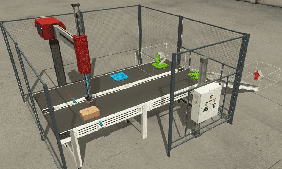
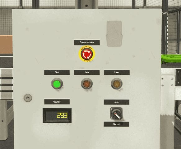
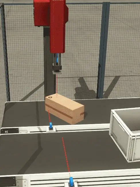
A normally open start and normally closed stop pushbuttons are used to start and stop the process in automatic mode. Upon starting the entry conveyor will bring a part to the item at the entry sensor. The conveyor will then stop. A robot arm will move down, detect the part, and then activate a grabber. It will then return to the up position. When it reaches the top it will extend the arm over the opposite exit conveyor. The exit conveyor will be stopped as the arm lowers the part to the conveyor. It releases the gripper and moves back up. The exit conveyor can then start. The arm returns to the entry conveyor. The entry conveyor will start again, to continue the same cycle. Upon a box being sensed from the item at the exit sensor, a counter will keep track of the number of complete cycles.
The reset input will reset the cycle counter and the machine. All items are removed off of the conveyor belts.
The manual mode will allow the function of the robot arm to step through the sequence without the conveyors running.
If the sequence stops for any reason, an error number will be displayed indicating where to look for the error on the machine.
Define the Inputs and Outputs: (2) – Pick and Place Programming Example
Inputs:
Item at Entry – Sensor – On/Off
Item at Exit – Sensor – On/Off
Moving X – Sensor – On/Off
Moving Z – Sensor – On/Off
Item detected – Sensor – On/Off
Start Pushbutton – Normally Open – On/Off
Reset Pushbutton – Normally Open – On/Off
Stop Pushbutton – Normally Closed – On/Off
Emergency Stop – Normally Closed – On/Off
Auto / Manual – Switch – On/Off
Outputs:
Entry Conveyor – Contactor – On/Off
Exit Conveyor – Contactor – On/Off
Move X – Contactor – On/Off
Move Z – Contactor – On/Off
Grap – Contactor – On/Off
Start Light – Contactor – On/Off
Reset Light – Contactor – On/Off
Stop Light – Contactor – On/Off
Counter – Register – 16 bits
Develop a logical sequence of operation: (3) – Pick and Place Programming Example
A flow chart or sequence table is used to fully understand the process the needs to be controlled. It must also answer questions like the following:
What happens when electrical power and/or pneumatic air is lost? What happens when the input / output devices fail? Do we need redundancy?
This step is where you can save yourself allot of work by understanding everything about the operation. It will help prevent you from continuously re-writing the PLC logic. Knowing all of these answers upfront is vital in the development of the PLC program.
Here is our sequence of operation for our pick and place application.
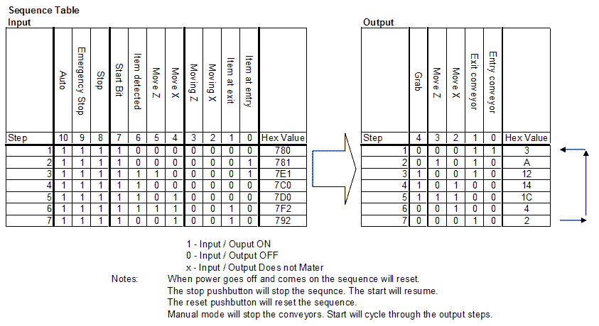
If our input conditions are true then the outputs are set. It will then look at the next step for the input conditions to set the outputs. Etc.
Develop the PLC program: (4) – Pick and Place Programming Example
Writing the code for the PLC will be the next step in our program development. A quick review can be seen on our post: Buiding A PLC Program That You Can Be Proud Of
(This series takes you through using discrete inputs and outputs to control traffic lights and cylinders. As we progress we introduce additional methods to solve logic. We look at sequencers in a new way and learn how to write programs to allow users to teach the new sequence.)
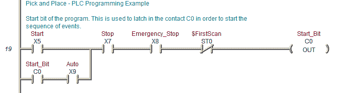
The first thing in our program is to control the start and stop functions. This is done through a latching circuit. You will see in the sequence table that I have included a start bit. This is because the start pushbutton is momentary.
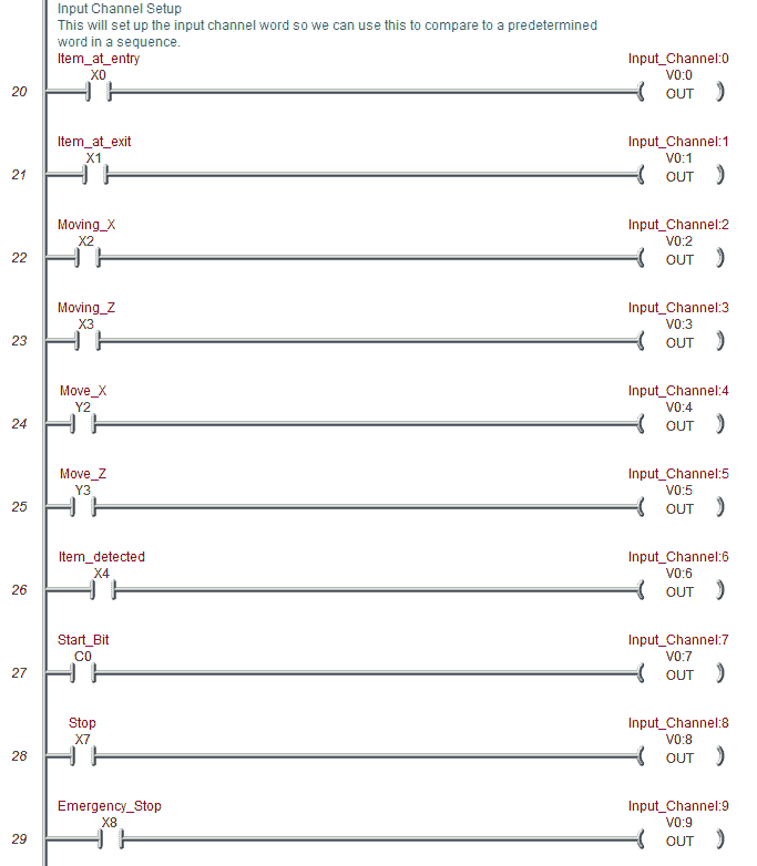
Inputs to our input word will now be programmed. This will allow us to view a register and compare it to a predetermined list.
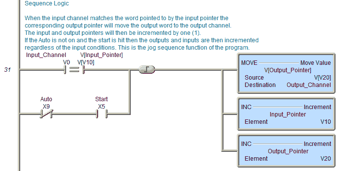
When the input channel matches the word pointed to by the input pointer the corresponding output pointer will move the output word to the output channel.
The input and output pointers will then be incremented by one (1).
If the Auto is not on and the start is hit then the outputs and inputs are then incremented regardless of the input conditions. This is the jog sequence function of the program.
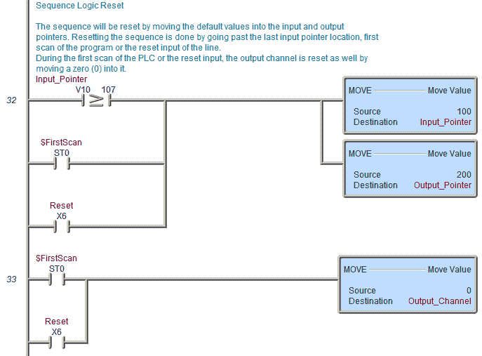
The sequence will be reset by moving the default values into the input and output pointers. Resetting the sequence is done by going past the last input pointer location, first scan of the program or the reset input of the line.
During the first scan of the PLC or the reset input, the output channel is reset as well by moving a zero (0) into it.
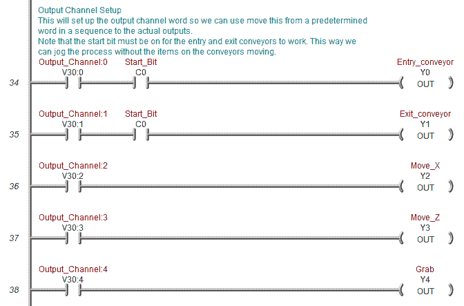
Output Channel Setup
This will set up the output channel word so we can use move this from a predetermined word in a sequence to the actual outputs.
Note that the start bit must be on for the entry and exit conveyors to work. This way we can jog the process without the items on the conveyors moving.
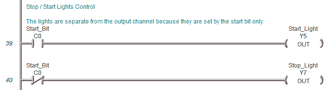
Stop / Start Lights Control
The lights are separate from the output channel because they are set by the start bit only.
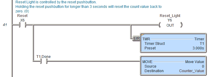
The reset light is controlled by the reset pushbutton.
Holding the reset pushbutton for longer than 3 seconds will reset the count value back to zero. (0)
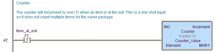
Counter
The counter will increment by one (1) when an item is at the exit. This is a one shot input so it does not count multiple items for the same package.
Error Display
When the following errors occur they relate to the following input (output) conditions. This will give the operator an idea of what the error is related to on the application.
Error Meaning
0 – Conveyor Entry
-1 – Conveyor Exit
-2 – Moving X
-3 – Moving Z
-4 – Move X
-5 – Move Z
-6 – Item Detected (Grip)
-7 – Start Bit
-8 – Stop Bit
-9 – Emergency Stop
-10 – Auto mode
When the start bit is on and the input pointer is greater than the first location, compare the input channel with the input channel table.
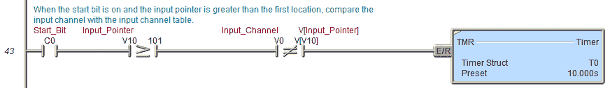
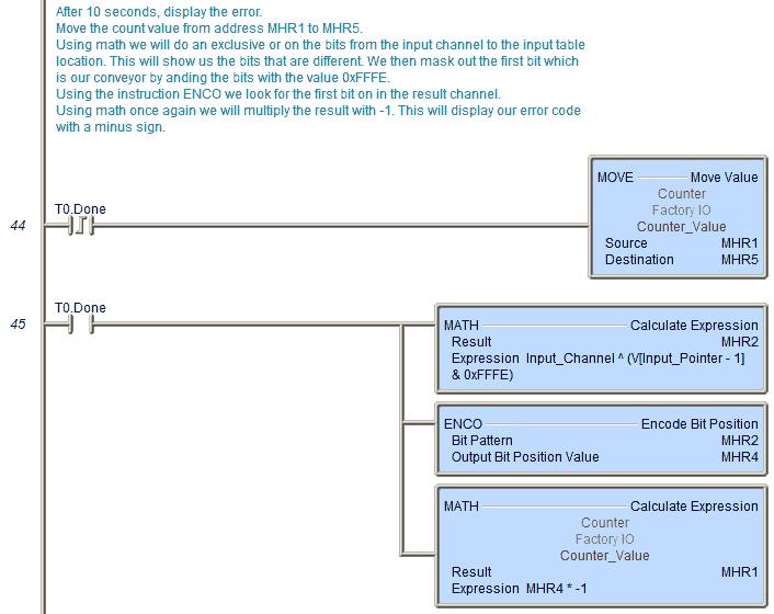
After 10 seconds, display the error.
Move the count value from address MHR1 to MHR5.
Using math we will do an exclusive or on the bits from the input channel to the input table location. This will show us the bits that are different. We then mask out the first bit which is our conveyor by anding the bits with the value 0xFFFE.
Using the instruction ENCO we look for the first bit on in the result channel.
Using math once again we will multiply the result with -1. This will display our error code with a minus sign.
When the error timer is reset, the count value is then returned to the display.
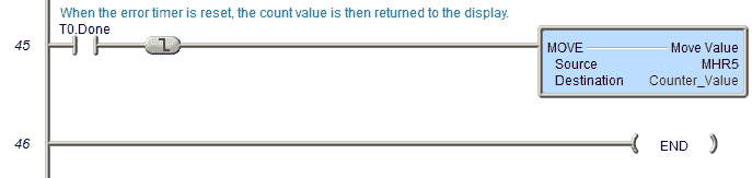
This is the end of our program.
Test the program: (5) – Pick and Place Programming Example
We will be using Factory IO to test the program. This communicates Modbus TCP Client (Master) to our BRX Series PLC (Modbus TCP Server (Slave)).
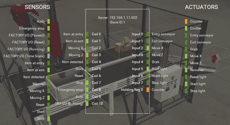
We will now add the inputs and outputs to our program for communication to our scene in Factory IO. The output coils from Factory IO will set the actual input addresses in our PLC. See the following post on Understanding the PLC Program Scan. This will demonstrate how we can set the actual PLC inputs.
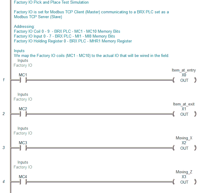
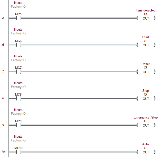
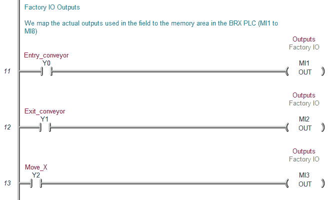
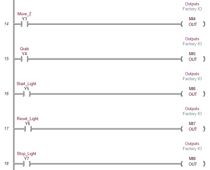
The inputs from Factory IO will be set by the actual outputs from our PLC.
The first step in testing out the program is to ensure that the inputs and outputs of the PLC are wired correctly. We would usually turn each input on manually and see the corresponding input of the PLC turn on. The same applies to the output devices. We would turn on each of the outputs to determine if they have been wired correctly.
Next, we will try our manual operations programmed into the process. If everything is working then we will start running our program in automatic mode.
Test the program for things that can go wrong. Unplug a sensor or remove a box after the sensor has seen it. The program should be able to react.
Watch the videos below to see an explanation and test of the program using Factory IO.
You can download the program and Factory IO scene here.
Watch on YouTube: PLC Programming Example – Pick and Place
If you have any questions or need further information please contact me.
Thank you,
Garry
If you’re like most of my readers, you’re committed to learning about technology. Numbering systems used in PLC’s are not difficult to learn and understand. We will walk through the numbering systems used in PLCs. This includes Bits, Decimal, Hexadecimal, ASCII and Floating Point.
To get this free article, subscribe to my free email newsletter.
Use the information to inform other people how numbering systems work. Sign up now.

The ‘Robust Data Logging for Free’ eBook is also available as a free download. The link is included when you subscribe to ACC Automation.