Traffic lights are used just about everywhere on busy roads around the world. They can help prevent traffic accidents and keep traffic flowing smoothly in the right direction by regulating the flow of cars, trucks, and other vehicles. The most common traffic light uses red, yellow, and green lights, along with arrows or flashes to indicate which lane should proceed when the lights change from green to yellow or red. Now you can visually see the 4-way traffic light by using the EasyPLC software suite. This provides an easy way of learning PLC programming.
 Using the five steps for PLC program development, we will discuss how to program this traffic light. Four traffic lights and pedestrian panels with push buttons will be used. We will be using an Automation Direct Click PLC for this application, but the general methods can be used for any PLC. Let’s get started.
Learn PLC programming the easy way. See below how to receive a 10% discount on this already cost-effective learning tool. Invest in yourself today.
Previously we have done the following:
Easy PLC Installing the Software – Video
EasyPLC Software Suite – Quick Start – Video
Click PLC – Easy Transfer Line Programming – Video
Productivity PLC Simulator – Chain Conveyor MS – Video
Do-More PLC – EasyPLC Box Selection Program – Video
Click PLC EasyPLC Gantry Simulator – Video
Click PLC Simple Conveyor EasyPLC – Video
EasyPLC Paint Line Bit Shift – BRX Do-More PLC – Video
Click PLC – EasyPLC PLC Mixer Programming – Video
Click PLC EasyPLC Warehouse Stacker Example – Video
– Operation Video
EasyPLC Machine Simulator Productivity PLC Robotic Cell – Video
EasyPLC Simulator Robotic Cell Click PLC – Video
EasyPLC Simulator Robotic Cell BRX Do-More PLC – Video
– EasyPLC Factory Editor Robotic Cell Additions Video
Define the task: (Step 1 – Easyplc Traffic Light)
The first step of PLC program development is determining what must be done. Traffic light control is an excellent way to learn PLC programming.
 The typical four-way traffic light intersection is generally well understood as what must happen. Each direction will have a red, green, and yellow light. Timers and outputs in the PLC operate in a sequence to control the operation of each light in all directions. The EasyPLC software suite contains this traffic light example in the machine simulator.
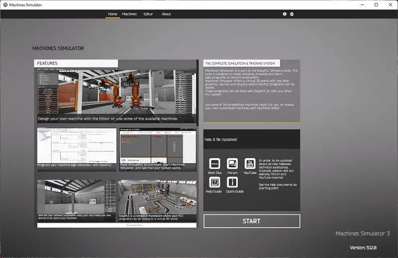
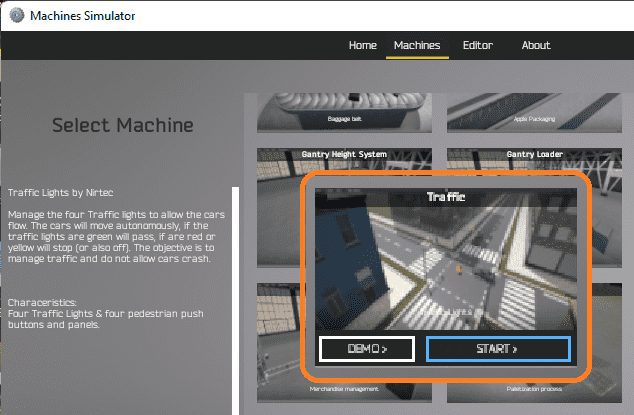
Start the EasyPLC Machine Simulator (MS). Select the start button on the main page or select machines from the menu at the machines simulator window.
 All the available machines will now be displayed. Click on the “Traffic.”
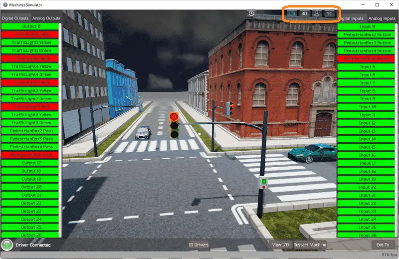
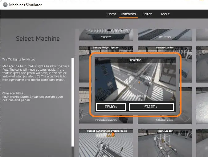 This is the example that we will be programming. To the left of the screen, information will be displayed on how the traffic lights function.
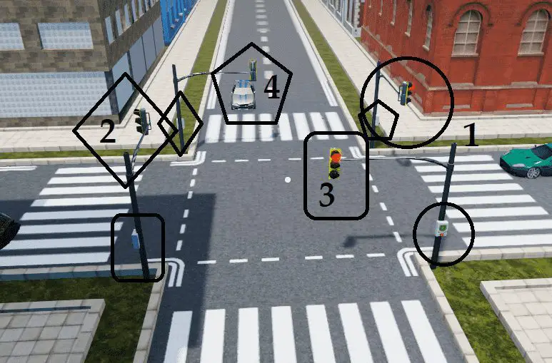
Manage the four traffic lights to allow the cars to flow. The vehicles will move autonomously; if the traffic lights are green, they will pass; if they are red or yellow, they will stop (or off); the objective is to manage traffic and not allow the cars to crash.
The machine simulator has a demo mode for the built-in machines. This will allow you to watch the operation of the robotic cell. Select the demo mode for the engine loading.
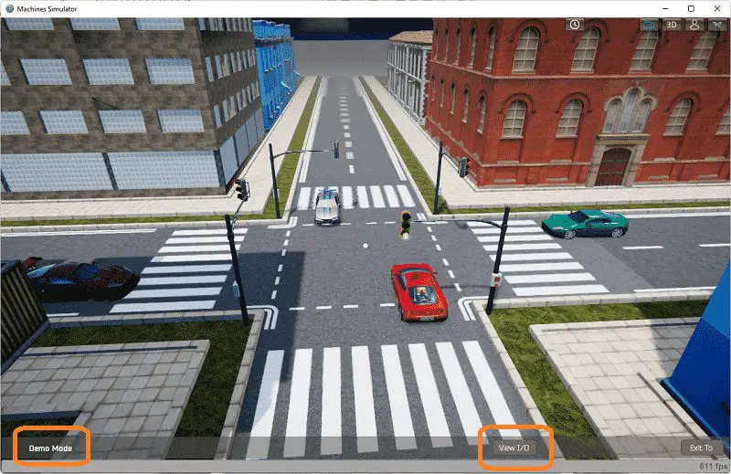 The traffic light demo mode on the machine simulator will operate, showing you the basics of operation.
Move around the 3D virtual environment. There are three icons on the top of the window that allows you to move around this 3D environment. The first icon is the default selection. This will enable you to move around without bumping into the components. The last icon will automatically show you around this virtual environment. The first-person mode will mimic a person in your 3D learning world. Once we understand what must be done, we can now move on to the next step in the PLC program development.
Define the Inputs and Outputs: (Step 2 – Easyplc Traffic Light)
At the bottom of the machine simulator window, the View IO will display the inputs and outputs required for this traffic light example. While still in demo mode, you can see the operation of the information and outcomes.
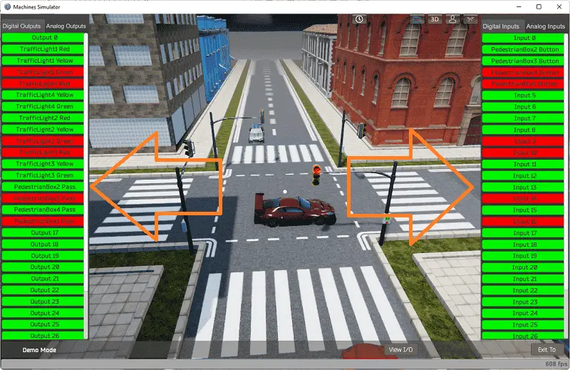 The EasyPLC 4-way traffic light example will require 16 digital inputs.
If you are unsure what output or input is doing, start the traffic light machine in Start mode.
 Select the View IO on the bottom middle of the machine simulator window. You can manually run the robotic cell without any control or PLC connected.
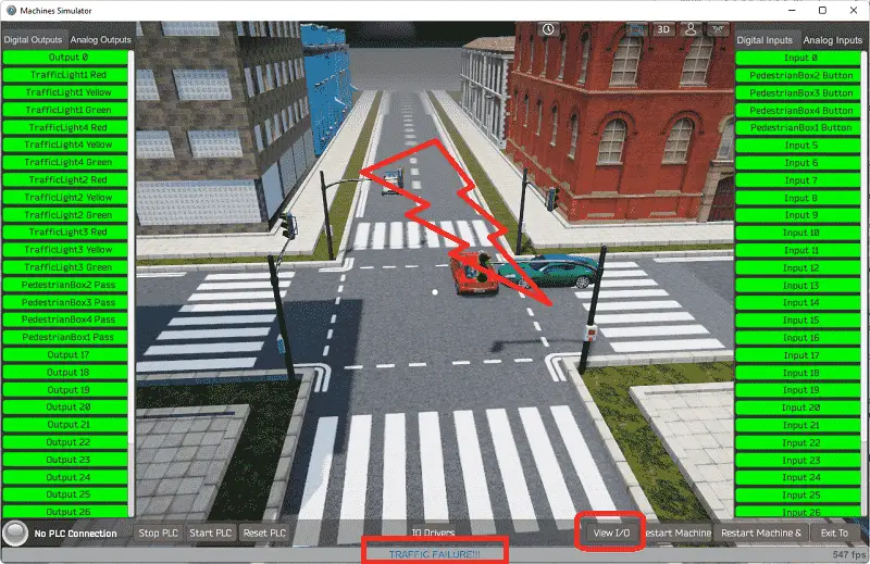 You will notice that a traffic failure will occur if you start the traffic light without manually turning on the red lights. This happens when two or more vehicles collide. The restart button on the bottom of the machine simulator window will reset the scene back to the start. Select the restart if this happens.
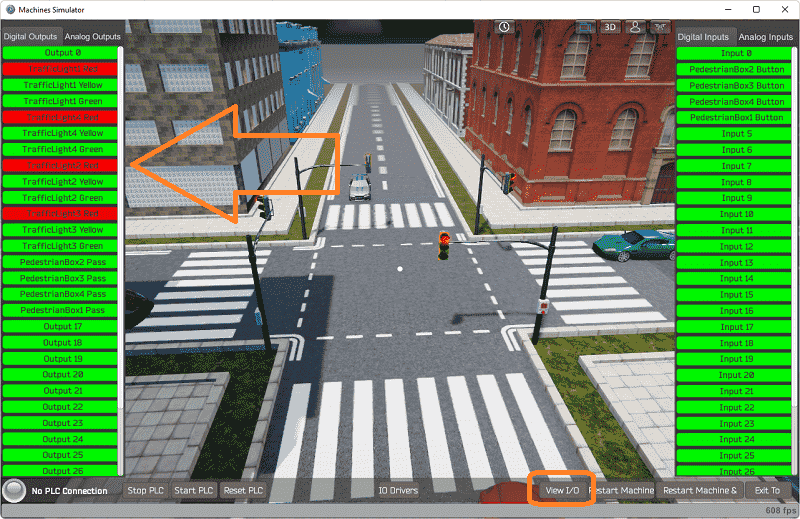 Clicking on the red light outputs will manually turn them on. Select the red lights once you have selected the view IO button. This will stop all traffic on the EasyPLC machine simulator.
Use the following PLC signals to control the traffic lights and pedestrian boxes. The following table will define the inputs and outputs (IO) and Modbus addresses in the Click PLC that we will use for this program.
| Digital Type | Description | Click PLC Modbus Address | Machine Simulator Modbus Address |
| PLC Output – MS Input | Output 0 | Y100 – 8224 | 8223 |
| PLC Output – MS Input | Traffic Light 1 Red | Y101 – 8225 | 8224 |
| PLC Output – MS Input | Traffic Light 1 Yellow | Y102 – 8226 | 8225 |
| PLC Output – MS Input | Traffic Light 1 Green | Y103 – 8227 | 8226 |
| PLC Output – MS Input | Traffic Light 4 Red | Y104 – 8228 | 8227 |
| PLC Output – MS Input | Traffic Light 4 Yellow | Y105 – 8229 | 8228 |
| PLC Output – MS Input | Traffic Light 4 Green | Y106 – 8230 | 8229 |
| PLC Output – MS Input | Traffic Light 2 Red | Y107 – 8231 | 8230 |
| PLC Output – MS Input | Traffic Light 2 Yellow | Y108 – 8232 | 8231 |
| PLC Output – MS Input | Traffic Light 2 Green | Y109 – 8233 | 8232 |
| PLC Output – MS Input | Traffic Light 3 Red | Y110 – 8234 | 8233 |
| PLC Output – MS Input | Traffic Light 3 Yellow | Y111 – 8235 | 8234 |
| PLC Output – MS Input | Traffic Light 3 Green | Y112 – 8236 | 8235 |
| PLC Output – MS Input | Pedestrian Box 2 Pass | Y113 – 8237 | 8236 |
| PLC Output – MS Input | Pedestrian Box 3 Pass | Y114 – 8238 | 8237 |
| PLC Output – MS Input | Pedestrian Box 4 Pass | Y115 – 8239 | 8238 |
| PLC Output – MS Input | Pedestrian Box 1 Pass | Y116 – 8240 | 8239 |
| PLC Input – MS Output | Input 0 | X100 – 100032 | 31 |
| PLC Input – MS Output | Pedestrian Box 2 Button | X101 – 100033 | 32 |
| PLC Input – MS Output | Pedestrian Box 3 Button | X102 – 100034 | 33 |
| PLC Input – MS Output | Pedestrian Box 4 Button | X103 – 100035 | 34 |
| PLC Input – MS Output | Pedestrian Box 1 Button | X104 – 100036 | 35 |
Note: The machine simulator will be offset by one on the Modbus Addresses.
See the video below for the demo mode and determining inputs and outputs.
Develop a logical sequence of operation: (Step 3 – Easyplc Traffic Light)
A PLC programmer must know how everything about the sequence and operation of the machine before programming. Traffic lights are an excellent way to learn to program because most people understand how they work. A flow chart or sequence table is used to understand the process that must be controlled thoroughly. It must also answer questions like the following:
What happens when electrical power and pneumatic air is lost? What happens when the input/output devices fail? Do we need redundancy?
This step is where you will spend most of your time. Understanding everything about the operation will save you time. It will help prevent you from continuously re-writing the PLC program logic. Knowing all these answers to how the system reacts is vital in developing the PLC program.
Here is the sequence table for the traffic lights.
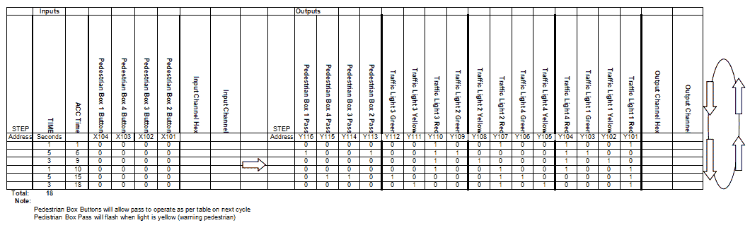 Put all inputs and outputs into the sequence table. This will allow you to determine what kind of control you will program. We can see that everything is based on time. Rearranging the sequence table, we can now use the following.
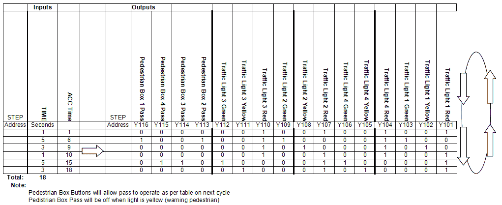 Here is the sequence table for the four-way traffic light. The input conditions are time or accumulated time. Outputs are set according to the time frame.
 The time after 18 seconds will reset back to 0 and continue timing. This will continually cycle through the table.
A PLC programmer must know how everything about the sequence and operation of the machine before programming.
Ask questions or view existing documentation to ensure that you know the logical steps to the machine operation.
Develop the Click PLC program: (Step 4 – Easyplc Traffic Light)
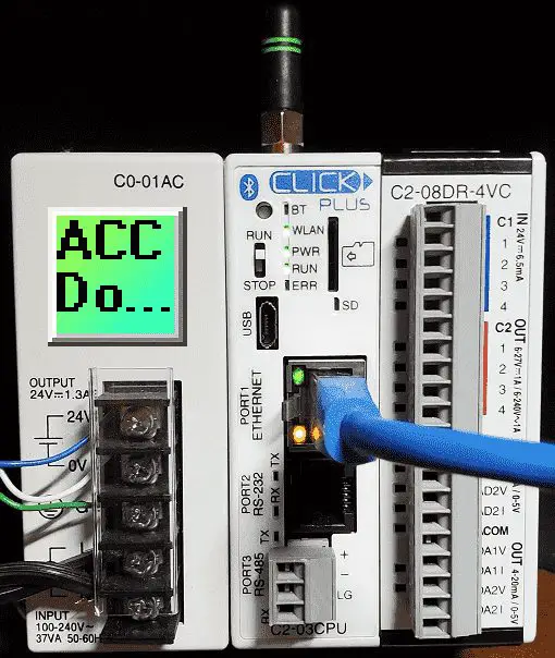
A programmable logic controller (abbreviated PLC) is an industrial computer that has been programmed to perform a variety of automated tasks based on various inputs and outputs. They are commonly used in manufacturing, construction, energy distribution, and process control applications. In basic terms: – The ladder logic programming language is used to instruct its function and operations that must be taken when a specific condition arises. Using the information from the previous step, we can now program our Click PLC. The Click / Click PLUS Series will show you details on how to use this popular modern PLC controller. This will include Click hardware, software, and ladder logic instructions. MQTT, Ethernet/IP, and Modbus are also discussed and demonstrated.
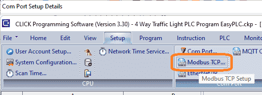
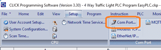 Select the Com Port under setup on the main menu. You can also call this up by selecting system configuration and clicking on the ports of the click picture.
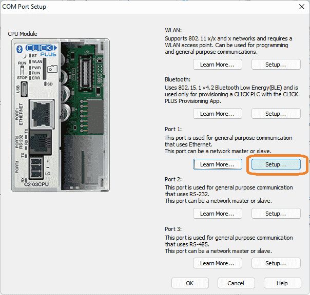 Select the setup button on the COM Port Setup window.
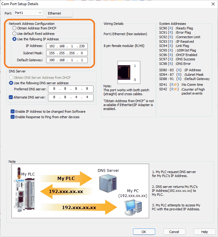 We will use a static IP address for the Ethernet port. Here are our settings for the Ethernet port.
 Select Modbus TCP to select the enable Modbus / TCP Server.
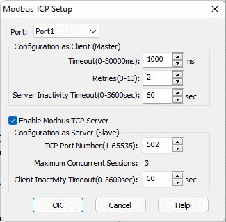 Our PLC is now set up as a Modbus TCP Server to the EasyPLC Modbus TCP Client. This is on by default, with port 502 as the default number. Everything is left as the default. We can change some of these settings if communication is not established reliably. Please note the static IP address that we are using for the BRX Do-More PLC. This will be used later to connect to the EasyPLC machine simulator.
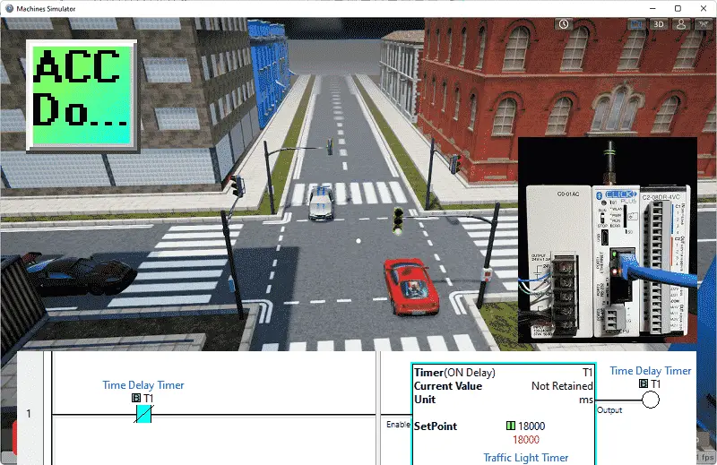
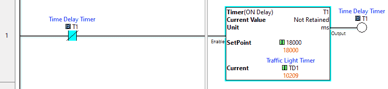 The first rung of the program will set up a self-resetting timer. Using a time base rate of milliseconds, the timer is set for 18,000 ms, 18 seconds. As soon as the timer reaches the set value, the timer bit will turn on. This will then reset the timer back to the set value.
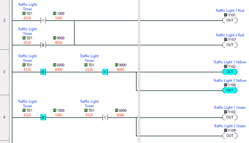 The next three rungs will control traffic lights 1 and 2. Traffic lights 1 and 2 operate simultaneously in our sequence table. This is done by comparing the timer to the times that the lights will be working. The sequence table determines the values required.
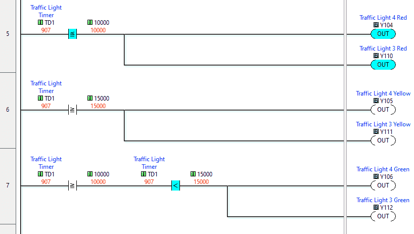 Traffic lights 3 and 4 also operate at the same time. Comparisons are again used to determine the time the lights are sequenced.
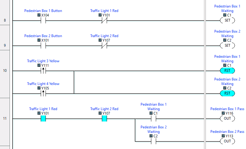 The pedestrian box will control the pass lights for that walk signal. Lights 1 and 2 are similar logic. The walk signals are handled separately. We have a pedestrian waiting signal activated when the button is pressed, and the light is not red. This ensures that the pedestrian has the entire time to cross the road. This signal is reset when the yellow traffic lights from 3 and 4 turn on. The actual pass light will turn on if traffic lights 1 and 2 are red, and the pedestrian waiting signal is activated.
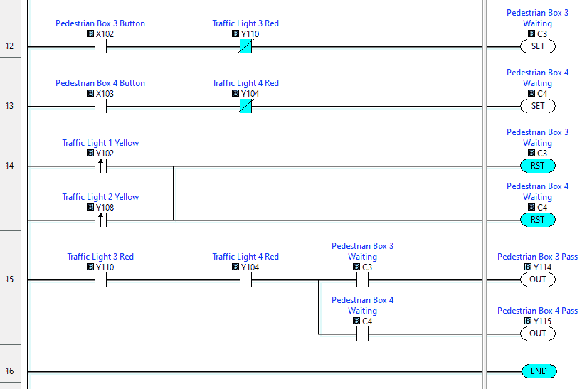 Pedestrian boxes 3 and 4 work similarly to boxes 1 and 2.
Our ladder logic program is complete. Download the program to the Click PLC. Ensure that the controller is in run mode.
Watch the video below to see this Click PLC program in action.
Test the program: (Step 5 – Easyplc Traffic Light)
We will be using Modbus TCP on our Click PLC to communicate to the EasyPLC Machine Simulator.
Call up the traffic simulator in start mode.
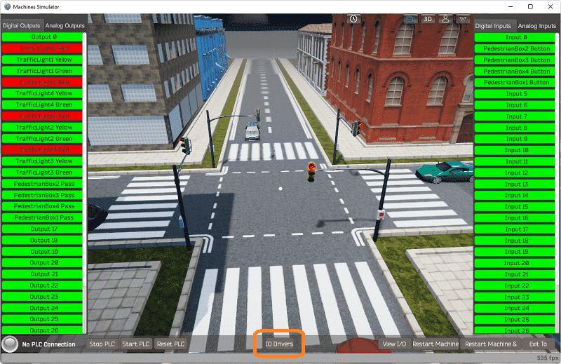 The status of the machine simulator will be along the bottom of the screen. Currently, we have no PLC connected. Select IO Drivers on the bottom middle of the screen.
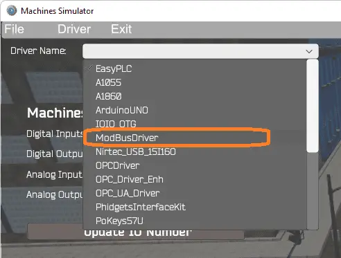 The EasyPLC driver is selected by default. Under the driver pull-down menu, select “ModBusDriver.” This driver will communicate Modbus TCP (Ethernet) and Modbus RTU (Serial). Select the down arrow on the driver’s name.
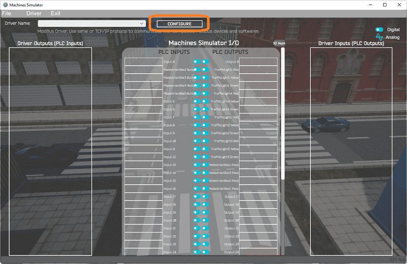 Select the configure button.
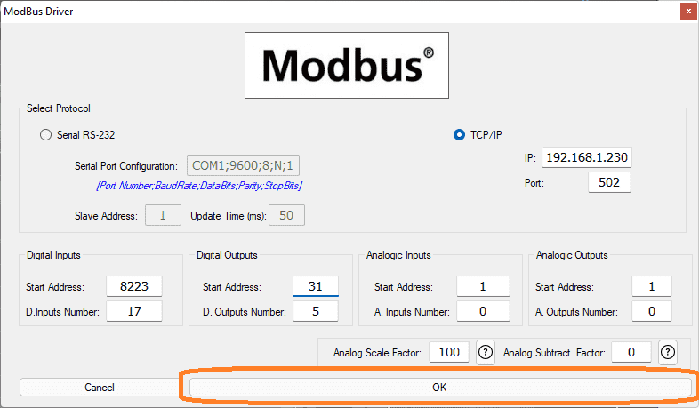 We can now enter the information for our Modbus driver. Select TCP/IP. This means the Ethernet port on the computer will communicate to the PLC.
The digital inputs from MS to the Click PLC will be Y101 to Y116. This will start at address 8223 because the offset of 1 and the first input are not used. Digital outputs from MS to the Click PLC will be X101 to X104. This will start at address 31 due to the offset of 1, and the first input is not used. Select the OK button.
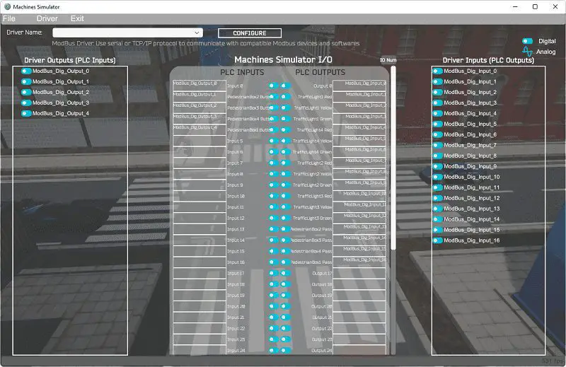
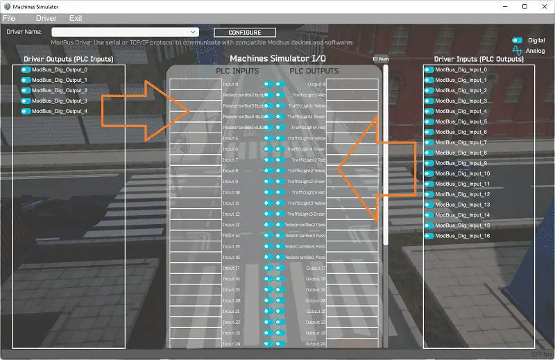 You will now see the inputs and outputs specified for the Modbus driver. We can now manually assign the driver outputs to the PLC inputs and the driver inputs to the PLC outputs. However, the automatic assignment works well and will save you time.
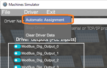 Select Automatic Assignment from the driver option in the main menu.
 This will automatically assign the PLC IO to the Machine Simulator IO.
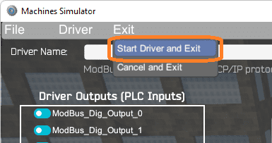 Select start driver and exit from the main menu.
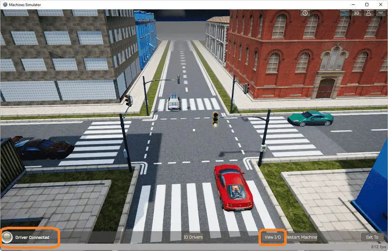 On the bottom left side of the window, you will see that the driver is communicating to the PLC by the green light. Select view IO to know the input and output status of the machine simulator.
 Ensure that the PLC is in run mode. We can see the operation of our 4 way traffic lights.
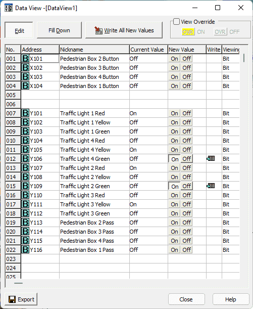 Using the Data View window of the Do-More Designer programming software, we can also watch the inputs and output operations.
Watch the video below to see this on the operation.
If your program works correctly, it’s time to move on. If not, you’ll need to debug. This can be as simple as re-downloading and re-uploading your program or redesigning your logic. When using EasyPLC, debugging is quickly done with no damage to any equipment. You may have to modify your logic several times before getting everything right! That’s okay—it’s all part of learning how a 4 way traffic light works. After all: trial and error are often easier said than done! To learn more about developing logic, check out our five steps to PLC program development.
 You can practice your modification and debug by modifying the traffic light in the following way:
– Add a 3-second flashing green for traffic lights 3. You will also have to change the pedestrian signals to ensure that you are not allowing them to pass.
Let me know how you make out in the comments below.
Download the Click PLC sample program and sequence table here.
Watch the video below to see the five steps of program development applied to the 4 way traffic lights. The machine simulator is one of the best applications to help you learn PLC programming.
EasyPLC Software Suite is a complete PLC, HMI, and Machine Simulator Software package. This PLC learning package includes the following:
Easy PLC – PLC Simulation allows programming in Ladder, Grafcet, Logic Blocks, or Script.
HMI System – Easily create a visual human-machine interface (HMI)
Machine Simulator – A virtual 3D world with real-time graphics and physical properties. PLC programs can be tested using the EasyPLC or through other interfaces. (Modbus RTU, TCP, etc.)
Machine Simulator Lite – Designed to run on Android Devices.
Machine Simulator VR – Virtual Reality comes to life so you can test, train or practice your PLC programming.
Purchase your copy of this learning package for less than USD 75 for a single computer install or less than USD 100 to allow different computers.
Receive 10% off the price by typing in ACC in the comment section when you order. http://www.nirtec.com/index.php/purchase-price/
Learn PLC programming the easy way. Invest in yourself today.
Watch on YouTube: 4 Way Traffic Light PLC Program EasyPLC
If you have any questions or need further information, please contact me.
Thank you,
Garry
If you’re like most of my readers, you’re committed to learning about technology. Numbering systems used in PLCs are not challenging to learn and understand. We will walk through the numbering systems used in PLCs. This includes Bits, Decimal, Hexadecimal, ASCII, and Floating Point.
To get this free article, subscribe to my free email newsletter.
Use the information to inform other people how numbering systems work. Sign up now.

The ‘Robust Data Logging for Free’ eBook is also available for free download. The link is included when you subscribe to ACC Automation.