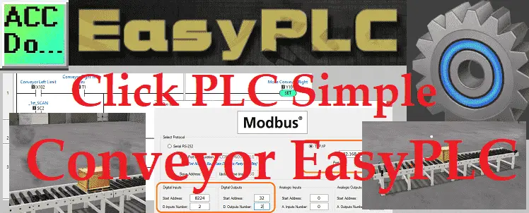
The Machine Simulator (MS) is part of the EasyPLC software suite. It has many built-in machines that can be programmed. A simple conveyor is one of these machines. This is usually the starting point for learning about the machine simulator. This conveyor example will use two digital inputs and two digital outputs. A pallet will move back and forth on the conveyor. When the pallet is detected on each end it will stop and reverse direction. If both motors are started at the same time, the motors will burn up. This will be demonstrated. The machine simulator will allow you as the programmer to make mistakes before trying your program in the physical world.
 The Click PLC will be used to program this virtual machine. Using the Click Plus PLC, we will connect the simulator to the simple conveyor machine. This will be done using Modbus TCP (Ethernet) for communications. Using the five steps for program development we will show how this is programmed. Let’s get started.
The Machine Simulator (MS) is part of the EasyPLC Software Suite. This is a complete PLC, HMI, and Machine Simulator Software package. This PLC learning package includes a Machine Simulator (MS). This virtual 3D world with real-time graphics and physical properties can communicate to several different programmable logic controllers. (PLC) See below to receive a 10% discount off of this PLC learning package. Invest in yourself today.
Previously we have done the following:
Easy PLC Installing the Software – Video
Click PLC – Easy Transfer Line Programming – Video
Productivity PLC Simulator – Chain Conveyor MS – Video
Do-More PLC – EasyPLC Box Selection Program – Video
Click PLC EasyPLC Gantry Simulator – Video
Define the task: (Step 1 – Simple Conveyor)
The first step of PLC program development is to determine what has to be done.
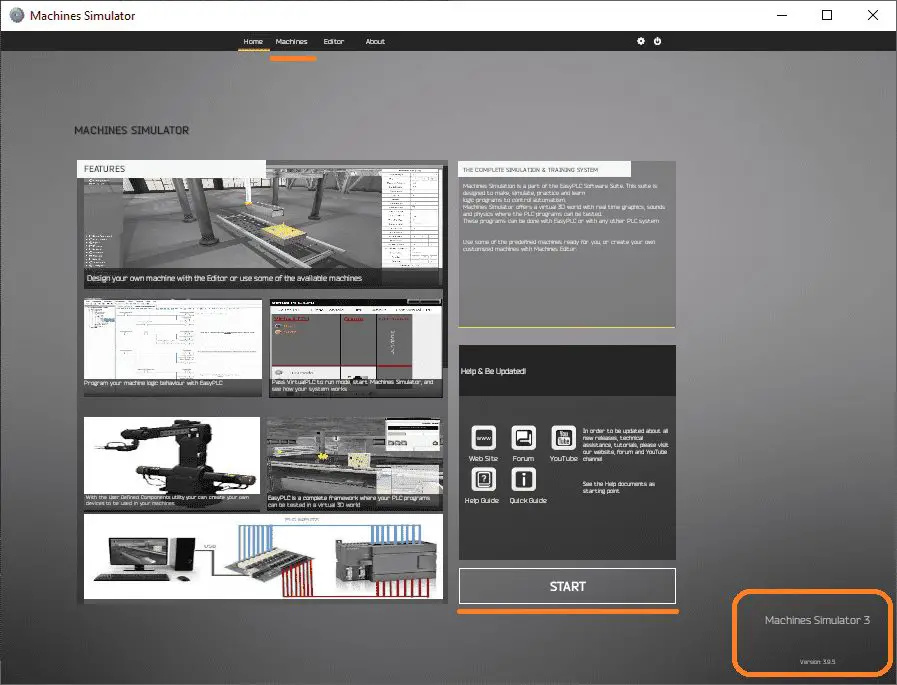 Start the EasyPLC Machine Simulator (MS). Select the start button on the main page or select machines from the main menu on the top of the machines simulator window.
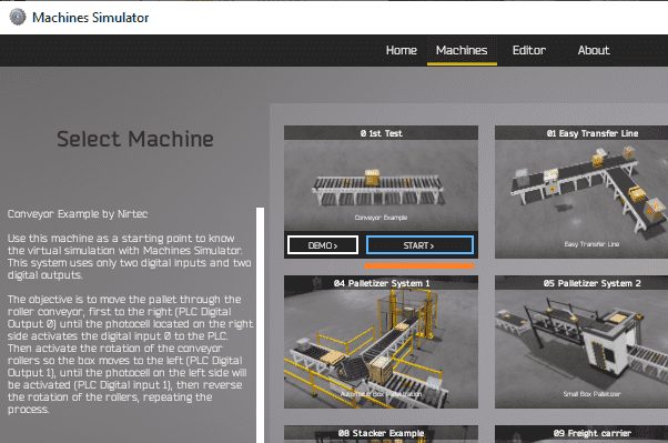 All of the available machines will now be displayed. Click on the 0 1st Test. This is the conveyor example that we will be programming. To the left of the screen, information will be displayed on what the machine needs to do as well as the inputs and outputs required for the program.
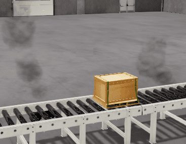
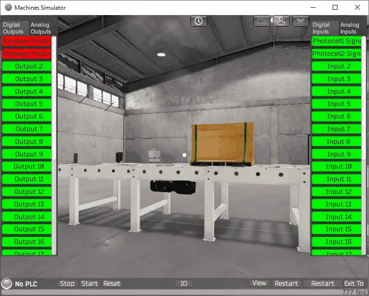
The machine simulator has a demo mode for the built-in machines. This will allow you to watch the operation of the simple conveyor. The objective is to move the pallet through the roller conveyor, first to the right (PLC Digital Output 0) until the photocell located on the right side activates the digital input 0 to the PLC. Then activate the rotation of the conveyor rollers do the box moves to the left (PLC Digital Output 1) until the photocell on the left side will be activated (PLC digital input 1), then reverse the rotation of the rollers, repeating the process.
Select the Start button for the conveyor example.
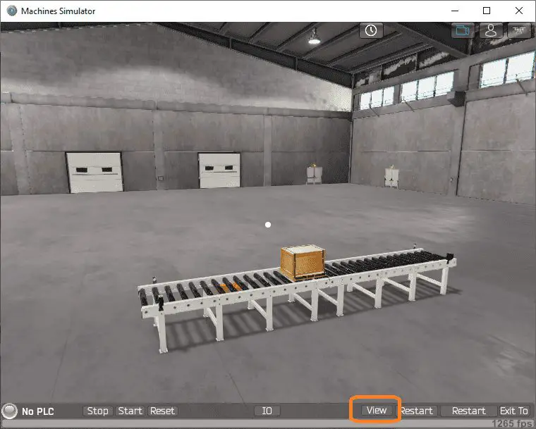 Select the View IO button located on the bottom of the machine simulator window.
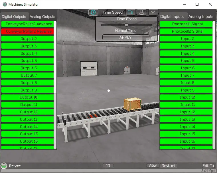
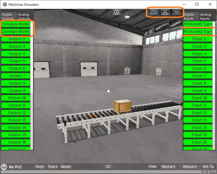 The outputs and inputs will now be displayed on the left-hand and right-hand sides of the window. There are also three icons on the top of the window that will allow you to move around this 3D environment. The first icon is the default selection. This will allow you to move around without bumping into the components. The first-person mode will mimic a person in your 3D learning world. Move around and operate your machine. The last icon will automatically show you around this virtual environment.
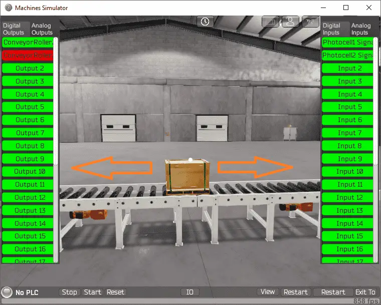 Clicking on the outputs will allow you to manually turn them on, moving the pallet. You can then monitor the inputs to see the photocells working. This manual mode will allow you to run the pallet off of the conveyor in either direction. If this happens, we can manually use the mouse to pick up and place the pallet back on the conveyor. Using the restart button on the bottom of the machine simulator window will reset the scene back to the start.
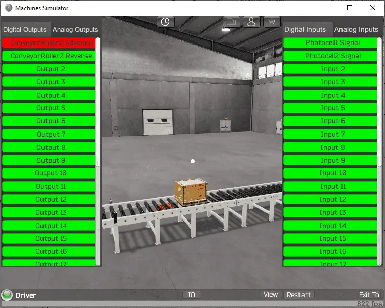
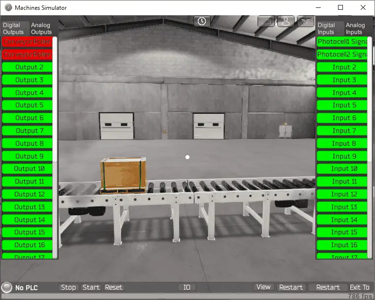 Energizing both the conveyor outputs together will cause the motors to smoke and turn black. When this happens, a reset for the MS needs to be done.
 Watch the testing of the simple conveyor video below. This will include manually running the pallet off of the end of the conveyor, moving the pallet, and burning the motors. The reset will also be demonstrated.
Define the Inputs and Outputs: (Step 2 – Simple Conveyor)
The View IO displayed the inputs and outputs required for this simple conveyor.
The conveyor example will require 2 digital outputs and 2 digital inputs.
The following table will define the inputs and outputs (IO) and Modbus addresses in the Click PLC that we will use for this program.
Digital Type Description Click Address Modbus Address MS Start Address
WorkPartCreatorPallet
ConveyorDistrib Advance
Conveyor Y101 8225 8224
Pneumatic
Start PB Light
Note: The machine simulator will be offset by one on the Modbus Addresses.
Using the address picker in the Click PLC programming software will show you the set Modbus addresses for this controller. See the video below.
Develop a logical sequence of operation: (Step 3 – Simple Conveyor)
A flow chart or sequence table is used to fully understand the process the needs to be controlled. It must also answer questions like the following:
What happens when electrical power and/or pneumatic air is lost? What happens when the input/output devices fail? Do we need redundancy?
This step is where you will spend the majority of your time. Understanding everything about the operation will save you time. It will help prevent you from continuously re-writing the PLC program logic. Knowing all of these answers upfront is vital in the development of the PLC program.
This program seems straightforward at first. We will add delays before sending the pallet in the opposite direction. 500 milliseconds will be used. A first scan flag in the PLC will also be used to start the pallet moving in one direction after a power cycle.
Future programs could track the time between the sensors to show conveyor speed. It could also keep track of run time to ensure maintenance on the conveyor is done.
A PLC programmer must know how everything about the sequence and operation of the machine before programming.
Ask questions or view existing documentation to ensure that you know the logical steps to the machine operation.
Develop the Click PLC program: (Step 4 – Simple Conveyor)
Writing the ladder logic code for the PLC example will be the next step in our program development. We will be using the Click programming software and a Click PLUS PLC.
The Click PLC Series will take you through installing the program, communicating to the controller, instructions, and addressing the controller.
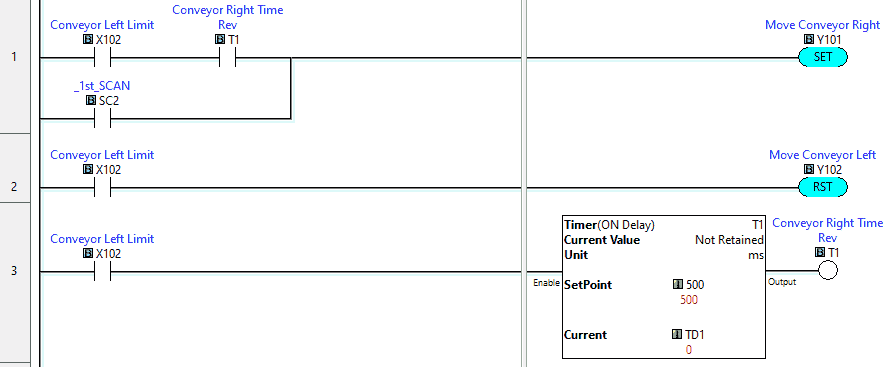 This first part of the PLC ladder logic will control the conveyor right movement. If the move left limit sensor is seen then this will stop the conveyor left movement and start a timer set for 0.5 seconds. When the timer expires then the move conveyor right is activated. The first scan of the PLC will also start the move conveyor right output.
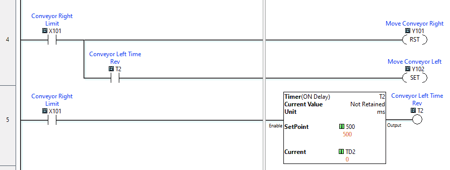 The conveyor right limit sensor will stop the conveyor right movement and start a timer for 0.5 seconds. When the timer expires then the moving conveyor left PLC output is activated.
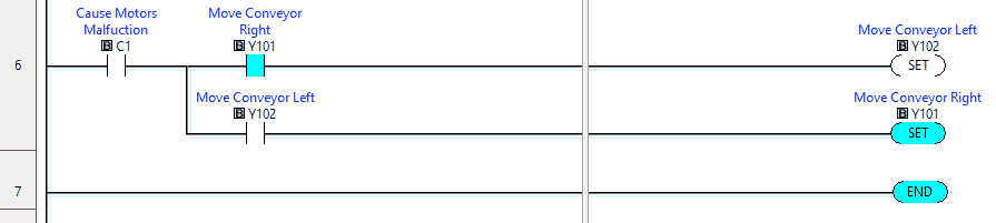 This final section of ladder logic will cause the motors to malfunction. C1 will set the other motor conveyor direction PLC output. This will cause both the left and right movements to happen at the same time. The motors will burn up, with smoke in the simulator. The EasyPLC machine simulator will then have to be reset.
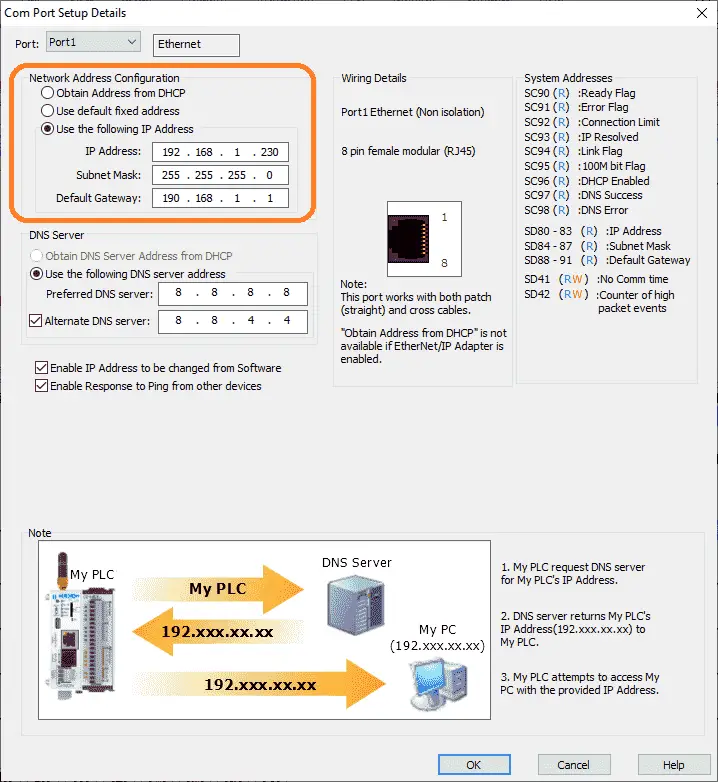 In order to communicate to the EasyPLC Machine Simulator, we must set up the Com Port in the Click PLC. Select main menu | Setup | Com Port… Alternatively, you can also select Com Port 1 Setup under the CPU Configuration on the Function tab of the Navigation window.
A static (fixed) IP address is used on the network to ensure that we know where the PLC is after power interruptions. Make a note of this address so we can enter the information in the EasyPLC simulator.
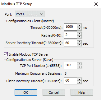 The Modbus TCP Setup can also be checked. Main menu | Setup | Modbus TCP… You can also select Modbus TCP under the Com Port Setup in the function tab of the navigation window. This enables the Modbus TCP server to be set as the default with port 502.
Save and transfer the PLC program to the Click. Ensure that the PLC is in Run mode.
Watch the video below to see this PLC program in action
Test the program: (Step 5 – Simple Conveyor)
We will be using Modbus TCP on our Click PLUS PLC to communicate to the EasyPLC Machine Simulator.
Call up the simple conveyor (0 1st Test) in start mode.
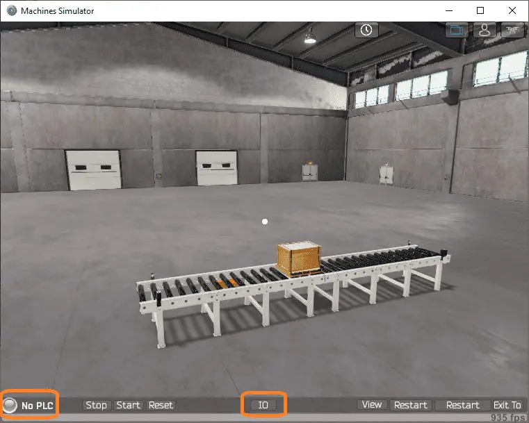 The status of the machine simulator will be along the bottom of the screen. Currently, we have no PLC connected.
 Select IO on the bottom middle of the screen.
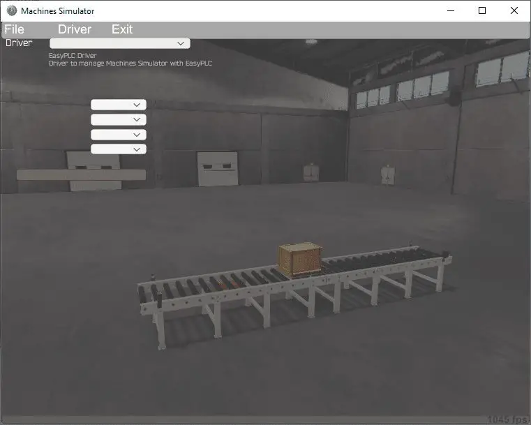
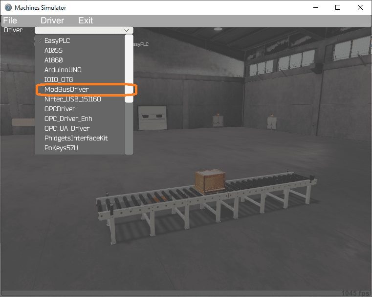 Under the driver pull-down menu, select “ModBusDriver”.
 This driver will communicate Modbus TCP (Ethernet) and Modbus RTU (Serial).
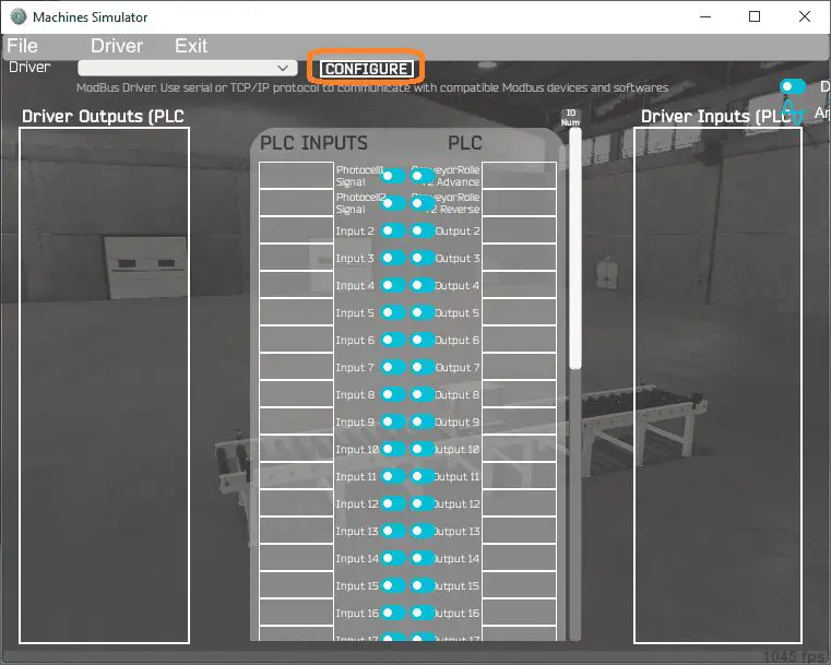
Select the configure button.
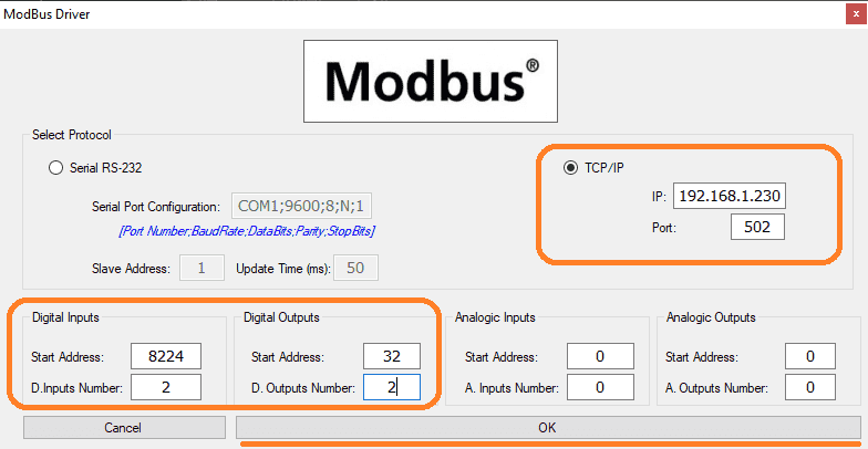 We can now enter the information for our Modbus driver. Select TCP/IP. This really means the Ethernet port on the computer will communicate to the PLC.
The digital inputs from MS to the Click PLC will be Y101 to Y102. This will start at address 8224 due to the offset of 1. Digital outputs from MS to the Click PLC will be X101 to X102. This will start at address 32 due to the offset of 1.
Select the OK button.
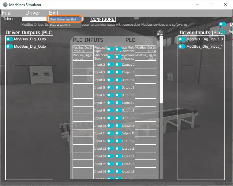
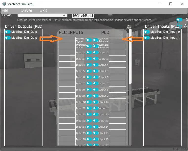 You will now see the inputs and outputs that we have specified for the Modbus driver. We can now manually assign the driver outputs to the PLC inputs and the driver inputs to the PLC outputs. However, the automatic assignment works well and will save you time.
 Select Automatic Assignment from the driver option in the main menu.
 This will automatically assign the PLC IO to the Machine Simulator IO.
Select start driver and exit from the main menu.
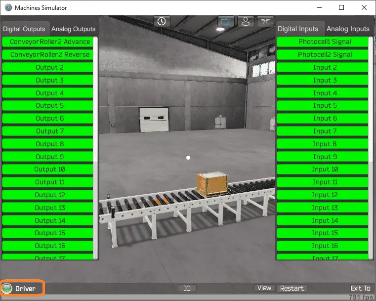 You will see on the bottom left side of the window that the driver is communicating to the PLC by the green light. Select view IO to see the input and output status of the machine simulator.
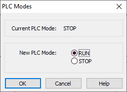 Ensure that the PLC is in run mode. We can see the operation of our simple conveyor moving the pallet.
 The digital inputs and outputs of the MS will correspond to the PLC controller.
 Using Machine Simulator (MS) to test the program will ensure that our program works.
Easy PLC machine simulator has a time frame that you can speed up or slow down the process to help you troubleshoot.
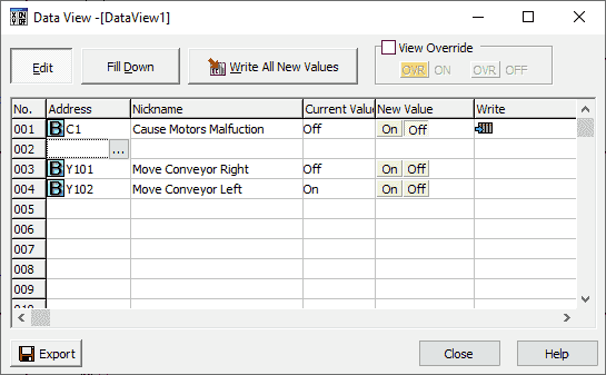 Using the Data View window of the Click programming software we can also watch the inputs and output operations.
Watch the video below to see this operation.
Download the Click PLC sample ladder logic program for the simple conveyor.
Watch the video below to see the five steps of program development applied to the simple conveyor. The machine simulator is one of the best applications to help you learn PLC programming.
EasyPLC Software Suite is a complete PLC, HMI, and Machine Simulator Software package. This PLC learning package includes the following:
Easy PLC – PLC Simulation that will allow programming in Ladder, Grafcet, Logic Blocks, or Script.
HMI System – Easily create a visual human-machine interface (HMI)
Machine Simulator – A virtual 3D world with real-time graphics and physical properties. PLC programs can be tested using the EasyPLC or through other interfaces. (Modbus RTU, TCP, etc.)
Machine Simulator Lite – Designed to run on Android Devices.
Machine Simulator VR – Virtual Reality comes to life so you can test, train or practice your PLC programming.
Purchase your copy of this learning package for less than $75 USD for a single computer install, or less than $100 USD to allow different computers.
Receive 10% off the price by typing in ACC in the comment section when you order. http://www.nirtec.com/index.php/purchase-price/
Learn PLC programming the easy way. Invest in yourself today.
Watch on YouTube: Click PLC Simple Conveyor EasyPLC
If you have any questions or need further information please contact me.
Thank you,
Garry
If you’re like most of my readers, you’re committed to learning about technology. Numbering systems used in PLCs are not difficult to learn and understand. We will walk through the numbering systems used in PLCs. This includes Bits, Decimal, Hexadecimal, ASCII, and Floating Point.
To get this free article, subscribe to my free email newsletter.
Use the information to inform other people how numbering systems work. Sign up now.

The ‘Robust Data Logging for Free’ eBook is also available as a free download. The link is included when you subscribe to ACC Automation.