The Machine Simulator (MS) is part of the EasyPLC software suite. It has many built-in machines that are used to show different programming techniques. The paint line is one of these machines. It will use a bit shift (shift register) to track bottles along a conveyor belt. All the bottles will be detected using photocells and tracked along the conveyor. Larger (taller) bottles will be painted and then pushed into a box at different sections of the conveyor belt. A control panel will be used to start and stop the paint line and display the bottle count. The paint line machine simulator is an excellent way to learn how to program shift registers (bit shift) in the PLC.
 The BRX Do-More PLC will be used to program this virtual paint line machine. Using the BRX Do-More PLC, we will connect to the paint line machine. This will be done using Modbus TCP (Ethernet) for communications. Using the five steps for program development we will show how this is programmed. Let’s get started.
Learn PLC programming the easy way. Invest in yourself today. See below on how to receive a 10% discount on this already cost-effective learning tool.
Previously we have done the following:
Easy PLC Installing the Software – Video
EasyPLC Software Suite – Quick Start – Video
Click PLC – Easy Transfer Line Programming – Video
Productivity PLC Simulator – Chain Conveyor MS – Video
Do-More PLC – EasyPLC Box Selection Program – Video
Click PLC EasyPLC Gantry Simulator – Video
Click PLC Simple Conveyor EasyPLC – Video
Define the task: (Step 1 – EasyPLC Paint Line Bit Shift)
The first step of PLC program development is to determine what has to be done. Start the EasyPLC Machine Simulator (MS). Select the start button on the main page or select machines from the main menu on the top of the machines simulator window.
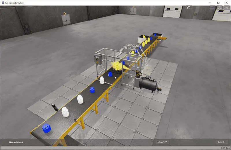
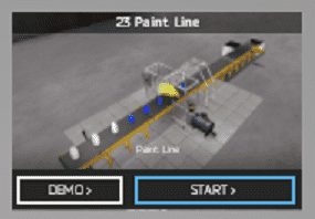
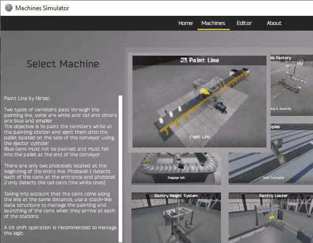 All of the available machines will now be displayed. Click on the 23 Paint Line. This is the example that we will be programming. To the left of the screen, information will be displayed on what the machine needs to do as well as some of the inputs and outputs required for the program.
Two types of canisters pass through the painting line. Some are white and tall and others are blue and smaller. The objective is to paint the canisters white at the painting station and eject them onto the pallet located on the side of the conveyor using the ejector cylinder.
Blue cans must not be painted and must fall into the pallet at the end of the conveyor.
There are only two photocells located at the beginning of the entry line. Photocell 1 detects each of the cans at the entrance and photocell 2 only detects the tall cans (white).
Taking into account the cans come along the line at the same distance, use a stack-like data structure to manage the painting and ejecting of the cans when they arrive at each of the stations. A bit shift operation is recommended to manage the logic.
 The machine simulator has a demo mode for the built-in machines. This will allow you to watch the operation of the paint line. Select the demo mode for the paint line.
 The paint line will operate showing you the basics of operation.
 Move around the 3D virtual environment. There are three icons on the top of the window that will allow you to move around this 3D environment. The first icon is the default selection. This will allow you to move around without bumping into the components. The first-person mode will mimic a person in your 3D learning world. The last icon will automatically show you around this virtual environment.
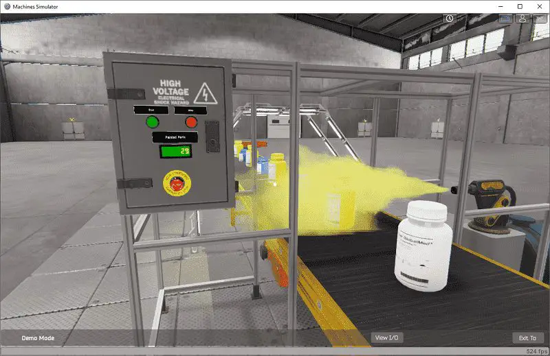
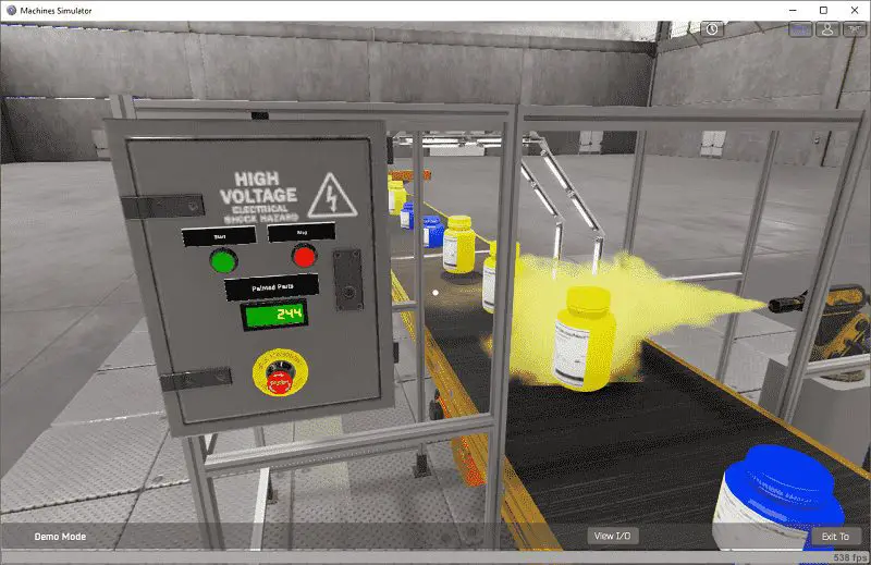
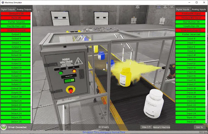
The control panel contains start, stop, and emergency stop buttons. There is a display that shows the total of the painted parts. You can see that only the taller white bottles are painted.
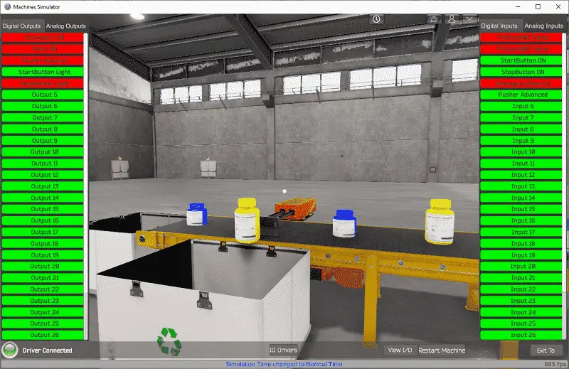
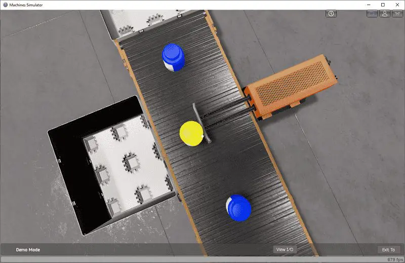 The eject station will only eject the taller white-painted bottles into the side pallet. Blue shorter bottles will continue on the conveyor, falling off into the end pallet.
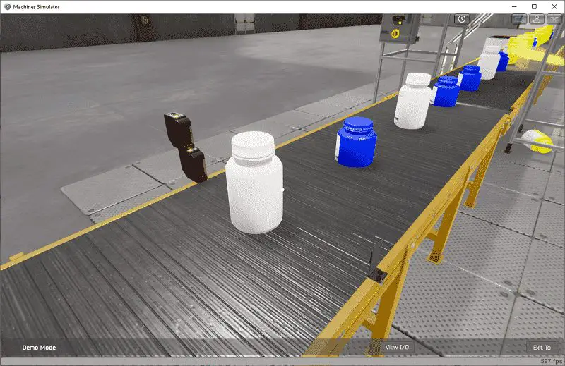 White taller bottles will activate both photocells.
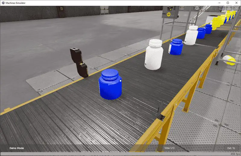 Smaller blue bottles will activate only the bottom photocell.
Once we have a good understanding of what has to be done, we can now move on to the next step in the PLC program development.
Define the BRX Do-More PLC Inputs and Outputs: (Step 2 – EasyPLC Paint Line Bit Shift)
In demo mode select View IO at the bottom of the machine simulator window. This will display the inputs and outputs required for this paint line conveyor.
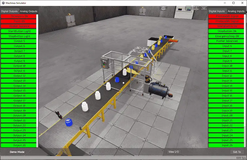 The EasyPLC paint line example will require 5 digital outputs and 6 digital inputs.
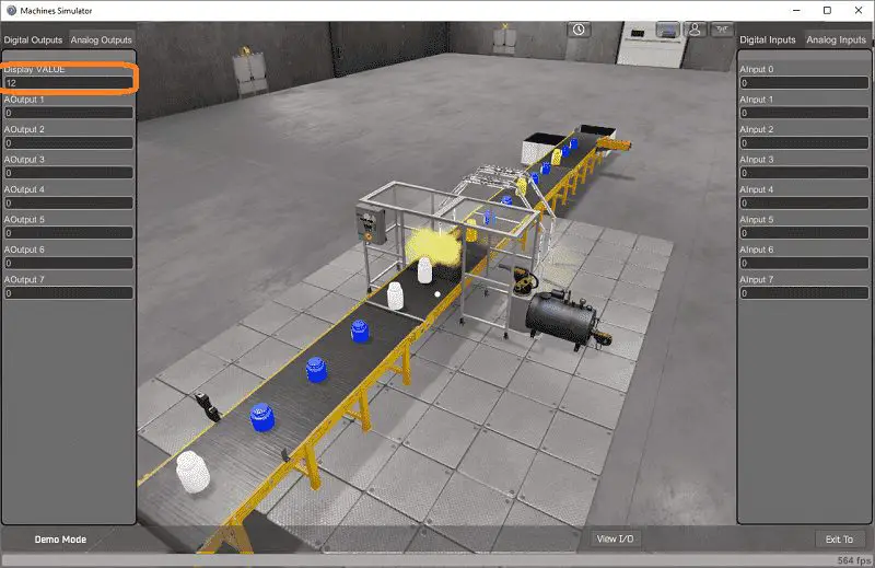 The display value will only use one analog output.
 If you are unsure as to what output or input is doing, start the paint line in Start mode. Select the View IO on the bottom middle of the machine simulator window. You can manually run the paint line without any control or PLC connected.
Clicking on the outputs will allow you to manually turn them on. You can then monitor the inputs to see their operation. Using the mouse, you can move the bottles in this 3D virtual environment. The restart button on the bottom of the machine simulator window will reset the scene back to the start.
The following table will define the inputs and outputs (IO) and Modbus addresses in the BRX Do-More PLC that we will use for this program.
| Digital Type | Description | Productivity Modbus Address | Machine Simulator Modbus Address |
| PLC Output – MS Input | Conveyor On | 10001 – MI1 | 0 |
| PLC Output – MS Input | Paint On | 10002 – MI2 | 1 |
| PLC Output – MS Input | Pusher Advance | 10003 – MI3 | 2 |
| PLC Output – MS Input | Start PB Light | 10004 – MI4 | 3 |
| PLC Output – MS Input | Stop PB Light | 10005 – MI5 | 4 |
| Analog PLC Output – MS Input | Painted Parts Count | 40001 – MHR1 | 0 |
| PLC Input – MS Output | PhotoCell 1 Signal | 1 – MC1 | 0 |
| PLC Input – MS Output | PhotoCell 2 Signal | 2 – MC2 | 1 |
| PLC Input – MS Output | Start PB On | 3 – MC3 | 2 |
| PLC Input – MS Output | Stop PB On | 4 – MC4 | 3 |
| PLC Input – MS Output | Emergency Stop | 5 – MC5 | 4 |
| PLC Input – MS Output | Pusher Advanced | 6 – MC6 | 5 |
Note: The machine simulator will be offset by one on the Modbus Addresses.
BRX Do-More PLC has a separate Modbus area. All of the Modbus addresses are dedicated to this series of controllers. See the video below.
Develop a logical sequence of operation: (Step 3 – EasyPLC Paint Line Bit Shift)
A flow chart or sequence table is used to fully understand the process the needs to be controlled. It must also answer questions like the following:
What happens when electrical power and/or pneumatic air is lost? What happens when the input/output devices fail? Do we need redundancy?
This step is where you will spend the majority of your time. Understanding everything about the operation will save you time. It will help prevent you from continuously re-writing the PLC program logic. Knowing all of these answers upfront is vital in the development of the PLC program.
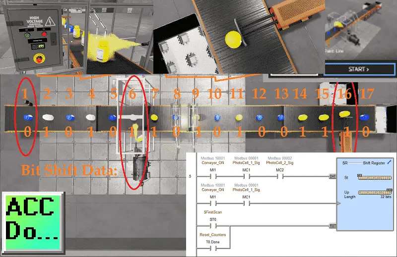
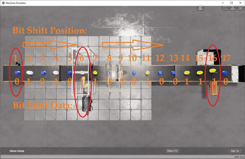 The EasyPLC paint line program will use bit shifting. Since the bottles are equally spaced on the conveyor belt, their position is fixed. This means that position 6 is the paint station and position 16 is the eject station.
Photocell 1 always detects each of the bottles. We will use this as our clock or shifting condition of the bits. It will be used to keep the timing of the shifting.
Photocell 2 will detect the tall white bottles. We will use this to put an on or 1 in our shift register. As photocell 1 shifts the register, photocell 2 indicates the tall bottle. You can see this in the picture above. A tall bottle (1 Bit) is at position 6, so the paint will operate. You will also see that a tall bottle is at position 16 (reject station) at the same time, so it will also activate.
 The green start button will start the paint line. The red stop button will stop the paint line. If the emergency stop button is activated, the paint line will not run.
If the line can be started, then the green push button light will be on. When the line is running, the red push button light will be on. If the emergency button is activated, both push-button lights will be off indicating that this must be reset.
The painted parts will be displayed on the panel. If the line is running and the start is pushed, the total blue smaller parts in the pallet will be displayed. If the line is stopped and the stop button is pushed, the total blue parts in the pallet will be displayed. Holding the stop button for more than 10 seconds will reset the blue total and painted part totals.
Future programs could track the bottle rate or ratio between the blue and white bottles. It could also keep track of run time to ensure maintenance on the conveyor is done.
A PLC programmer must know how everything about the sequence and operation of the machine before programming.
Ask questions or view existing documentation to ensure that you know the logical steps to the machine operation.
Develop the BRX Do-More PLC program: (Step 4 – EasyPLC Paint Line Bit Shift)
Writing the ladder logic code for the PLC example will be the next step in our program development. We will be using the Do-More Designer programming software and a BRX Do-More PLC.
The BRX Do-More PLC Series will take you through installing the program, communicating to the controller, instructions, and addressing the controller.
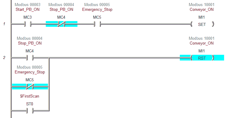 The first part of the BRX Do-More PLC ladder logic will control the conveyor. It will start if the start push button is pressed and the stop and emergency stop are in their normal state. (Not Active)
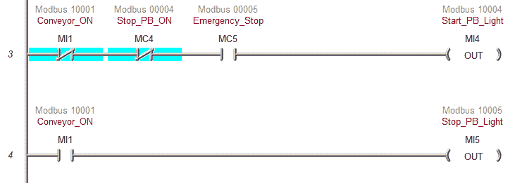 The start push button light will be on if the paint line is ready to start. In our case, the emergency stop is not in its normal state so both the start and stop lights are off. When the machine is running the stoplight is on.
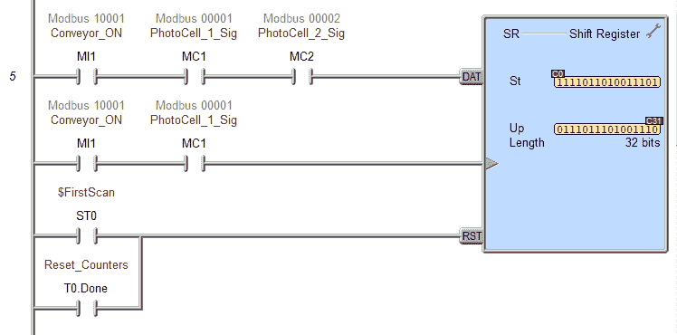 A shift register is used to control the paint line. It has three input rungs to control the bits shifting. The first one is the data. When the conveyor is on and we have both photocells, one is placed in the shift register. If it is off then a zero is placed in the shift register. The second input is the clock bit. This controls when to shift the data. (bit shift) If the conveyor is on and we have photocell 1 come on then the input is triggered. The triangle on the input of the clock is to indicate a leading-edge or one shot on the input. A reset of the shift register happens when the first scan flag is activated or the reset is done. This will zero out all of the bits (C0 to C31) of our shift registers.
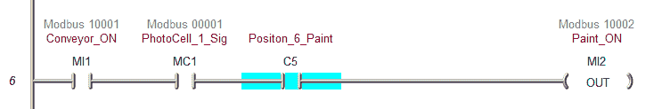 The paint output is controlled by C5 of the shift register. This is position 6 in our paint line. The paint will be on when the conveyor is running. Photocell 1 will determine the time that the paint output is on.
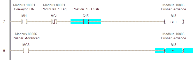 The pusher advance is controlled by C15 of the shift register. This is position 16 (bit shift) in our paint line. The conveyor must be running and the leading edge of photocell 1 with the C15 bit will set the pusher advance. Once the pusher advanced input is seen the pusher is reset.
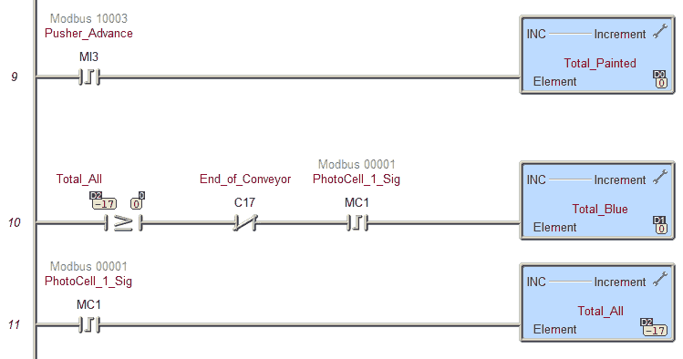 The leading edge of the pusher advance will increment our total painted amount in the pallet beside the paint line.
Our total blue bottles will be counted once we have accounted for all of the bottles on the conveyor (17). Then we look for a zero in the shift register (bit shift) at position 18 and the leading edge of photocell 1 to increment the total blue counter.
Internally we also keep track of the total amount in the pallets and from the reject forward.
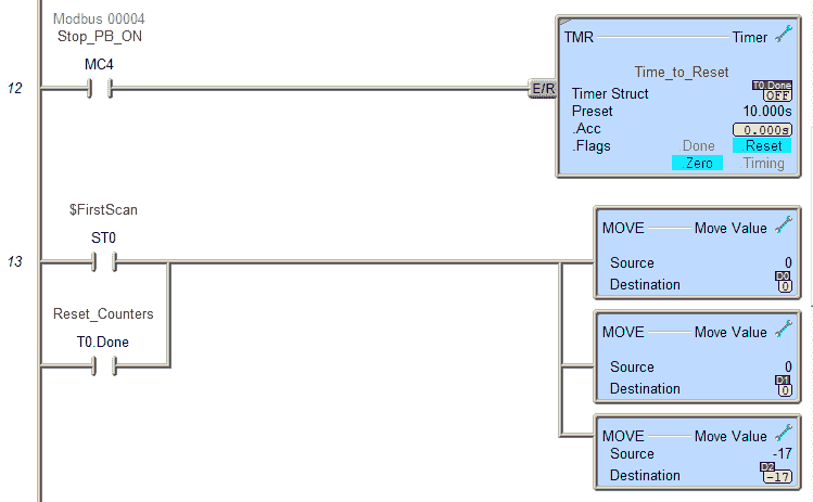 Pressing and holding the stop push button for more than 10 seconds will trigger the reset of the counters. The first scan of the BRX Do-More PLC will also perform a reset. The total bottle count will start at -17 because this is how many bottles we need until they are near the pallets.
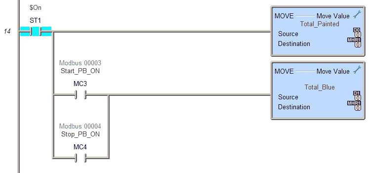 The total painted will always be displayed on the paint line control panel. If the start or stop push button is selected, the total blue in the pallet will be displayed.
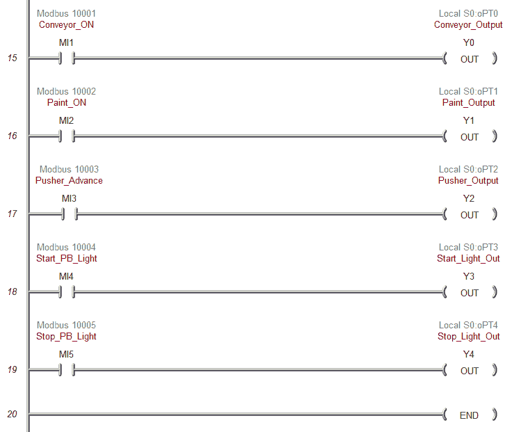 Activating the physical outputs of the BRX Do-More PLC can happen based on the control. MI1 to MI5 will control outputs Y0 to Y4. Watch the video below to see these outputs working.
In order to communicate to the EasyPLC Machine Simulator, we must set up the Ethernet Port on the BRX Do-More PLC. Select main menu | PLC | System Configuration… Alternatively, you can also select system configuration under tools in the project browser of the Do-More Designer programming software.
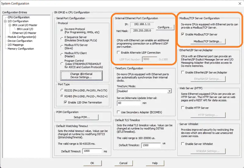 A static (fixed) IP address is used on the network to ensure that we know where the BRX Do-More PLC is after power interruptions. Make a note of this address so we can enter the information in the EasyPLC simulator. This enables the Modbus TCP server to be set as the default with port 502.
Save and transfer the PLC program to the BRX Do-More PLC. Ensure that the PLC is in Run mode.
Watch the video below to see this BRX Do-More PLC program in action
Test the program: (Step 5 – EasyPLC Paint Line Bit Shift)
We will be using Modbus TCP on our BRX Do-More PLC to communicate to the EasyPLC Machine Simulator.
Call up the paint line machine simulator in start mode.
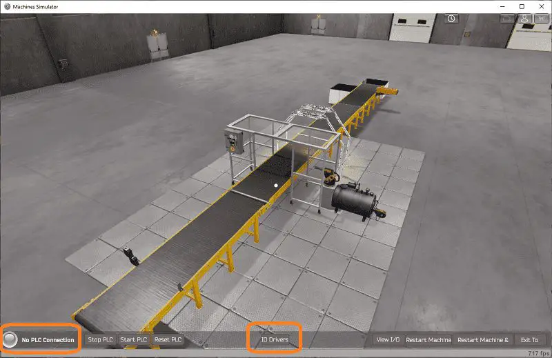 The status of the machine simulator will be along the bottom of the screen. Currently, we have no PLC connected. Select IO Drivers on the bottom middle of the screen.
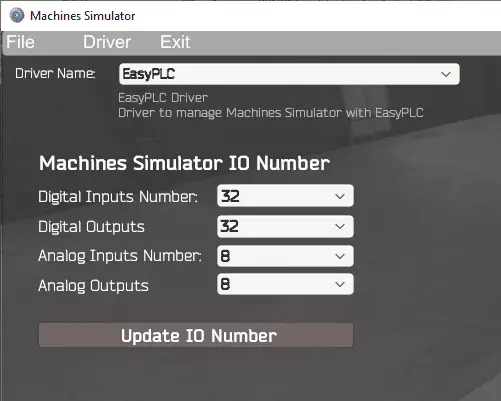 The EasyPLC driver is selected by default. Select the down arrow on the driver’s name.
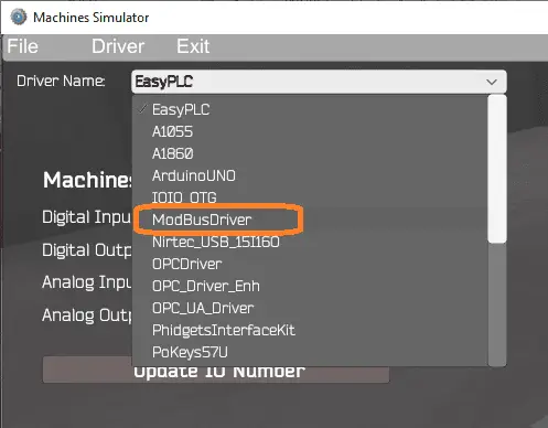 Under the driver pull-down menu, select “ModBusDriver”.
 This driver will communicate Modbus TCP (Ethernet) and Modbus RTU (Serial).
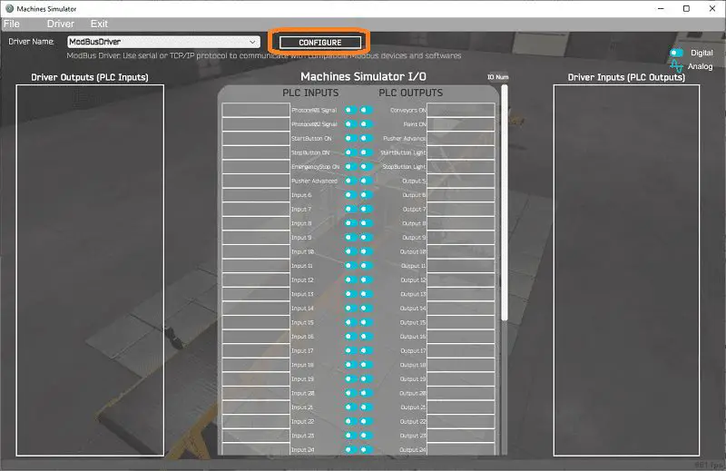
Select the configure button.
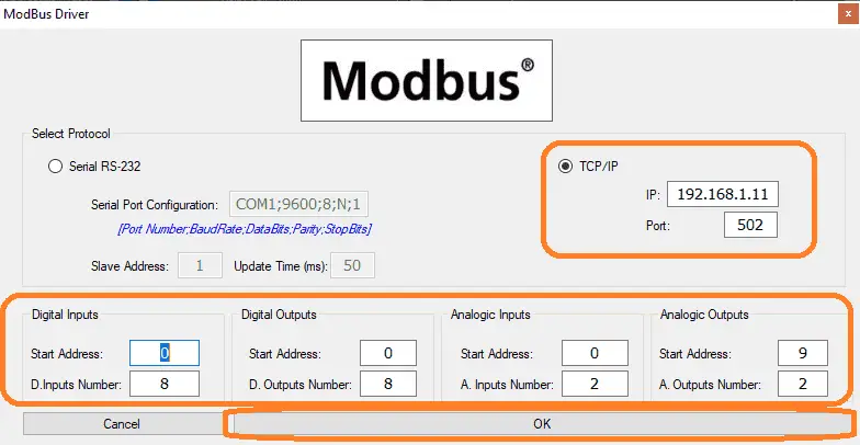 We can now enter the information for our Modbus driver. Select TCP/IP. This really means the Ethernet port on the computer will communicate to the PLC.
The digital inputs from MS to the BRX Do-More PLC will be MI1 to MI8. This will start at address 0 due to the offset of 1. Digital outputs from MS to the BRX Do-More PLC will be MC1 to MC8. This will start at address 0 due to the offset of 1. We are only using one analog input to the paint line. This will be at MHR1 in the BRX Do-More PLC.
Select the OK button.
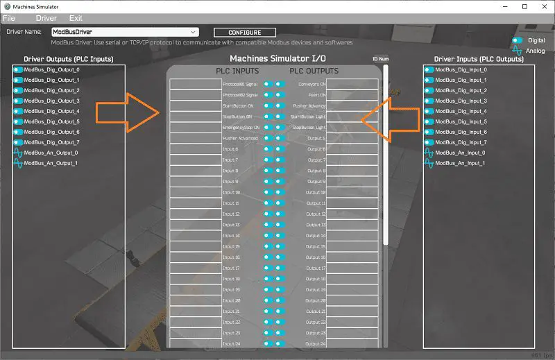 You will now see the inputs and outputs that we have specified for the Modbus driver. We can now manually assign the driver outputs to the PLC inputs and the driver inputs to the PLC outputs. However, the automatic assignment works well and will save you time.
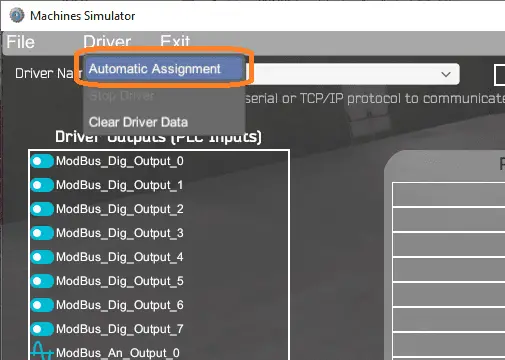 Select Automatic Assignment from the driver option in the main menu.
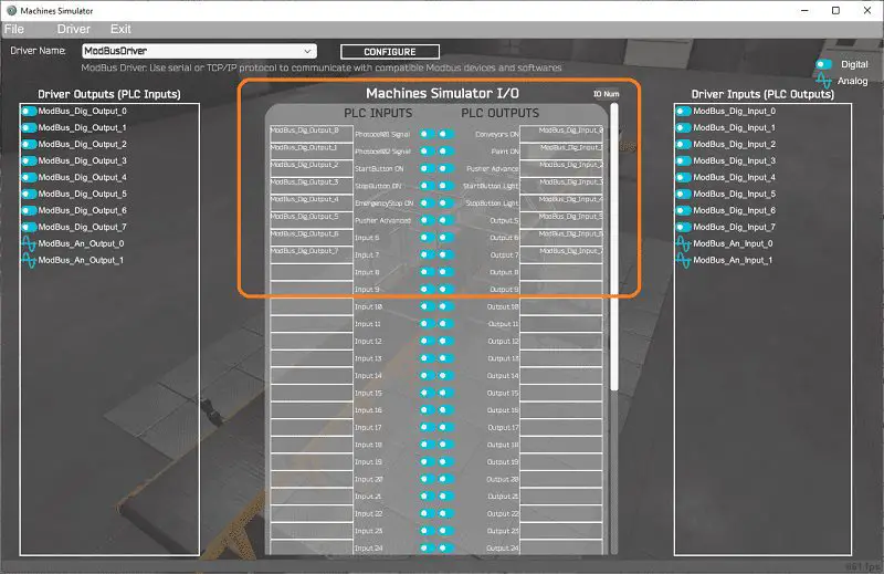 This will automatically assign the PLC IO to the Machine Simulator IO.
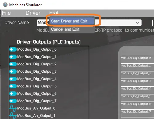 Select start driver and exit from the main menu.
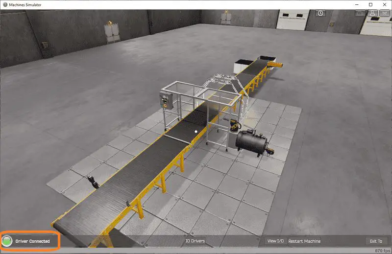 You will see on the bottom left side of the window that the driver is communicating to the PLC by the green light. Select view IO to see the input and output status of the machine simulator.
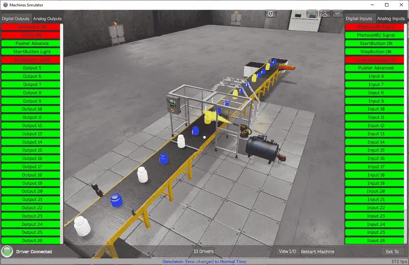
 Ensure that the BRX Do-More PLC is in run mode. We can see the operation of our simple conveyor moving the pallet. Select the start push button on the control panel.
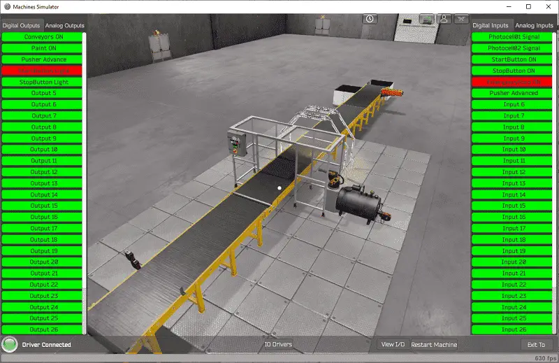
 The digital inputs and outputs of the MS will correspond to the PLC controller.
 Using Machine Simulator (MS) to test the program will ensure that our program works.
Easy PLC machine simulator has a time frame that you can speed up or slow down the process to help you troubleshoot.
 Using the Data View window of the Do-More Designer programming software we can also watch the inputs and output operations.
Watch the video below to see this operation.
Download the BRX Do-More PLC sample program and position chart for the Paint Line.
Watch the video below to see the five steps of program development applied to the paint line. The machine simulator is one of the best applications to help you learn PLC programming.
EasyPLC Software Suite is a complete PLC, HMI, and Machine Simulator Software package. This PLC learning package includes the following:
Easy PLC – PLC Simulation that will allow programming in Ladder, Grafcet, Logic Blocks, or Script.
HMI System – Easily create a visual human-machine interface (HMI)
Machine Simulator – A virtual 3D world with real-time graphics and physical properties. PLC programs can be tested using the EasyPLC or through other interfaces. (Modbus RTU, TCP, etc.)
Machine Simulator Lite – Designed to run on Android Devices.
Machine Simulator VR – Virtual Reality comes to life so you can test, train or practice your PLC programming.
Purchase your copy of this learning package for less than $75 USD for a single computer install, or less than $100 USD to allow different computers.
Receive 10% off the price by typing in ACC in the comment section when you order. http://www.nirtec.com/index.php/purchase-price/
Learn PLC programming the easy way. Invest in yourself today.
Watch on YouTube: EasyPLC Paint Line Bit Shift – BRX Do-More PLC
If you have any questions or need further information please contact me.
Thank you,
Garry
If you’re like most of my readers, you’re committed to learning about technology. Numbering systems used in PLCs are not difficult to learn and understand. We will walk through the numbering systems used in PLCs. This includes Bits, Decimal, Hexadecimal, ASCII, and Floating Point.
To get this free article, subscribe to my free email newsletter.
Use the information to inform other people how numbering systems work. Sign up now.

The ‘Robust Data Logging for Free’ eBook is also available as a free download. The link is included when you subscribe to ACC Automation.