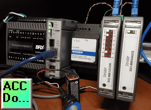
We will now look at the BRX Do-More PLC Modbus TCP remote io using Stride Field io. The BRX Do-More PLC can use remote inputs and outputs from Stride. The Stride Field I/O Modules are simple and compact. They provide an economical means to connect inputs and outputs to an Ethernet Modbus TCP communication network. Every module operates as a standalone Modbus TCP server and can be configured via a built-in web server.
Previously we looked at the Stride Field Remote IO Modules Modbus TCP Ethernet wiring and configuration.
Stride Field Remote IO Modules Modbus TCP Ethernet
– Unboxing SIO MB12CDR and SIO MB04ADS Video
– Powering and Configuring Video
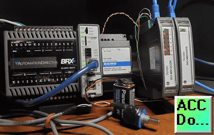
We will be connecting two Stride remote inputs and outputs to the BRX Do-More PLC. Modbus TCP will be the protocol over Ethernet to communicate to the SIO-MB12CDR and SIO-MB04ADS units.
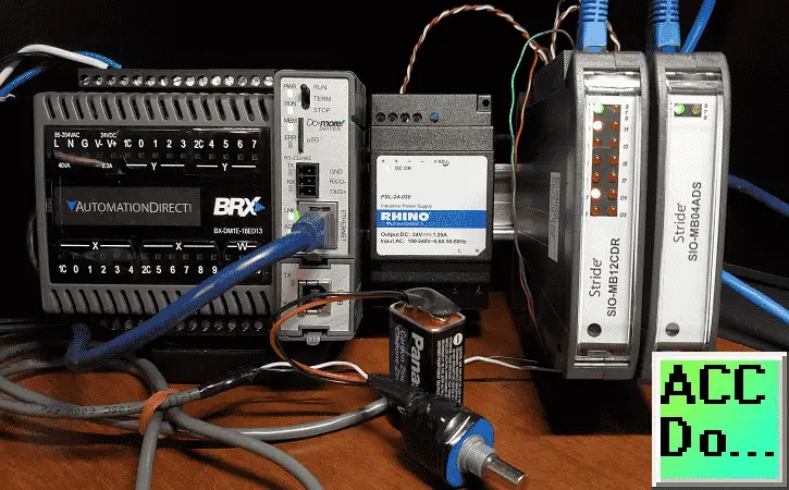
SIO-MB12CDR
– STRIDE discrete combo module, Input: 8-point, 12-24 VDC, sinking, Output: 4-point, relay, (4) Form C (SPDT) relays, 2A/point, (1) Ethernet (RJ45) port(s), Modbus TCP server.
SIO-MB04ADS
– STRIDE analog input module, 4-channel, current/voltage, 16-bit, isolated, input current signal range(s) of +/- 20 mA, input voltage signal range(s) of +/- 10 VDC, (1) Ethernet (RJ45) port(s), Modbus TCP server.
We will be reading an analog voltage into the BRX Do-More PLC from the remote IO unit. We will then set an output to pulse on and off at a time range indicated by this analog signal. The output will be on the other remote IO unit and will trigger the input to signal. We will look at the Frequency, Count, and Status of this input. Our BRX Do-More PLC program will also take into consideration watchdog (communication time out) and power-up events for the Stride remote input and output units.
Let’s get started.
Previously in this BRX series PLC, we have discussed:
System Hardware – Video
Unboxing – Video
Installing the Software – Video
Establishing Communication – Video
Firmware Update – Video
Numbering Systems and Addressing – Video
First Program – Video
Monitoring and Testing the Program – Video
Online Editing and Debug Mode – Video
Timers – Video
Counters – Video
High-Speed IO – Video
Compare Instructions – Video
Math Instructions – Video
Program Control – Video
Shifting Instructions – Video
Drum Instruction – Video
Serial Communication – Modbus RTU to Solo Process Temperature Controller – Video
Data Logging – Video
Email – Text SMS Messaging Gmail – Video
Secure Email Communication Video
AdvancedHMI Communication – Modbus TCP – Video
Analog IO – System Configuration – Video
HTTP JSON Instructions – Video
Analog Dusk to Dawn Program – Video
INC DEC 512 Registers for DMX512 – Video
PID with PWM Output – Video
PID Ramp Soak Profile – Video
Do-More Simulator MQTT Publish / Subscribe – Video
BRX Do-More PLC MQTT Communications – Video
Stride Field Remote IO Modules Modbus TCP Ethernet
– Unboxing SIO MB12CDR and SIO MB04ADS Video
– Powering and Configuring Video
Our entire series can be found here.
https://accautomation.ca/series/brx-do-more-plc/
The programming software and manuals can be downloaded from the Automation Direct website free of charge.
Watch the video below to see BRX Do-More PLC control analog and digital inputs and outputs remotely.
BRX Do-More PLC System IP Addresses
Our BRX plc will act as the Modbus Client (Master). It will communicate to the stride remote I/O which are Modbus Servers (Slaves).
Call up the COM Port Setup window by using the main menu | PLC | System Configuration…
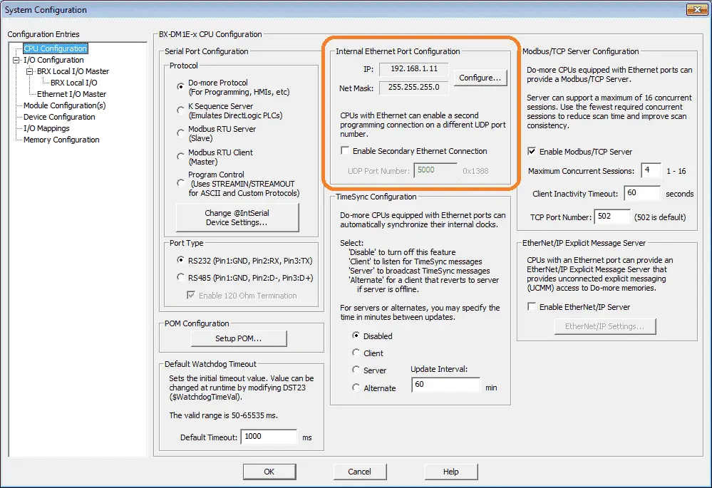
Select the CPU Configuration on the left-hand side. You will see the Internal Ethernet Port Configuration. Select the Configure… button.
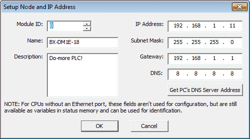
Here is where we can set our IP address for the BRX PLC Ethernet port.
We will set the Stride SIO-MB12CDR and Stride SIO-MB04ADS to 131 and 132 respectfully. This is shown in the configuration of the Stride remote IO above.
System Modbus Remote IO Wiring
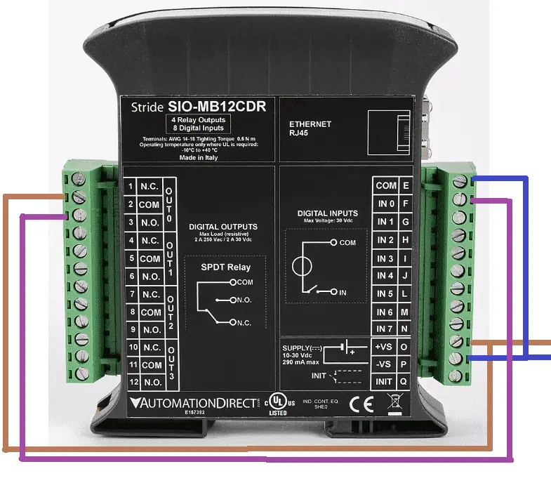
The first relay output of the Stride SIO-MB12CDR will be wired to the input of the first 24-volt sourcing input. This will allow us to see the input working and view the frequency and count values of the unit.
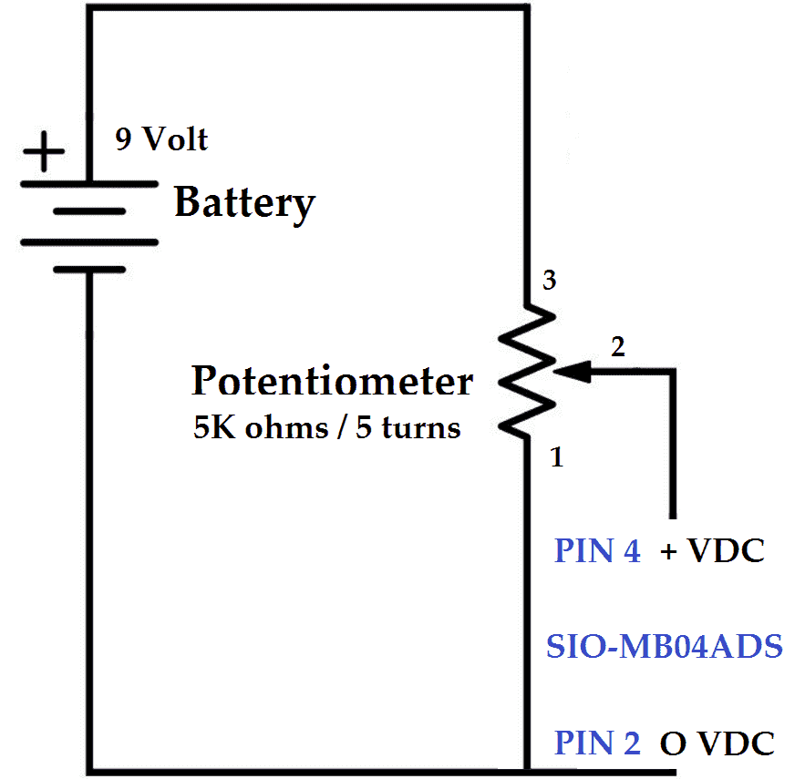
Using the voltage input tester that we created previously, we will be wiring this up to the first voltage input on the Stride SIO-MB04ADS unit.
Create an Analog Voltage Input Tester for a PLC – Video
BRX Do-More PLC Modbus Remote IO Program
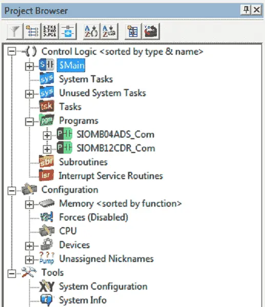
Our sample program has a Main program that will do the overall logic. It will call up two programs that will handle the communications to the stride remote inputs and outputs.
SIOMB12CDR_Com – Communications to the Stride SIO-MB12CDR (Discrete I/O)
SIOMB04ADS_Com – Communications to the Stride SIO-MB04ADS (Analog Input)
Main Modbus TCP Remote IO Program
The main program will control the call to the communication programs and handle the main logic.
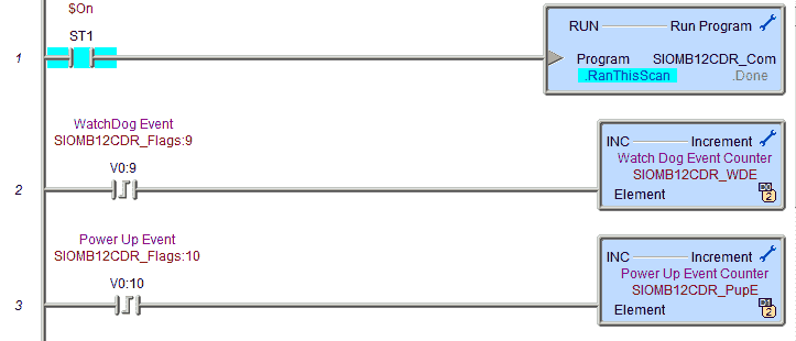
The first rung of code will call the communication subroutine for the SIO-MB12CDR. The watchdog timer event and the power-up event flags from the remote input and output unit will increment D0 and D1 respectfully.
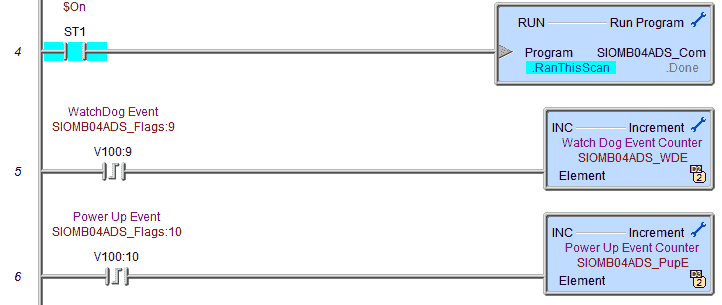
Rung four will call the communication subroutine for the SIO-MB04ADS. The watchdog timer event and the power-up event flags from the remote input and output unit will increment D2 and D3 respectfully.
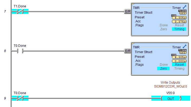
The analog input will control the on and off timer delay. This delay will control the first relay output. It will basically turn on and off based on the time set by the analog input.
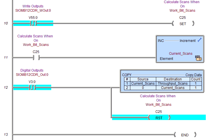
The following lines of code will count the number of scans based on the relay output for the remote turning on and then the acknowledgment that the output is on from the remote IO unit. This will give users a good idea of the throughput of the system.
Watch the video below to see this program in action.
SIO-MB12CDR Remote IO Program
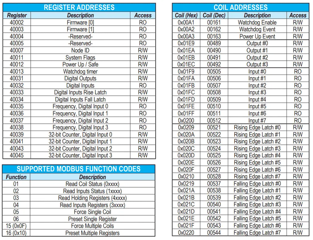
Here is the Modbus address chart for the remote IO unit.
Note: We have included all of the addresses and features of the card in our sample program. Your program may not need all of these features.
We will map the following with our program:
System Flags:
V0:8 – WatchDog Event Enable
V0:9 – WatchDog Event
V0:10 – Power Up Event
Digital Relay Outputs:
Output 1 – V3:0 – Status – V55:0 – Control
Output 2 – V3:1 – Status – V55:1 – Control
Output 3 – V3:2 – Status – V55:2 – Control
Output 4 – V3:3 – Status – V55:3 – Control
Digital Input Addresses:
Input 0 – V4:0 – Rising Edge – V5:0 – Falling Edge – V6:0
Input 1 – V4:1 – Rising Edge – V5:1 – Falling Edge – V6:1
Input 2 – V4:2 – Rising Edge – V5:2 – Falling Edge – V6:2
Input 3 – V4:3 – Rising Edge – V5:3 – Falling Edge – V6:3
Input 4 – V4:4 – Rising Edge – V5:4 – Falling Edge – V6:4
Input 5 – V4:5 – Rising Edge – V5:5 – Falling Edge – V6:5
Input 6 – V4:6 – Rising Edge – V5:6 – Falling Edge – V6:6
Input 7 – V4:7 – Rising Edge – V5:7 – Falling Edge – V6:7
V53 – Reset Rising Edge Flags – 0x0000
V54 – Reset Falling Edge Flags – 0x0000
Input 0 Frequency – V7
Input 1 Frequency – V8
Input 2 Frequency – V9
Input 3 Frequency – V10
Input 0 32-bit Counter – V11 V12
Input 1 32-bit Counter – V13 V14
Input 2 32-bit Counter – V15 V16
Input 3 32-bit Counter – V17 V18
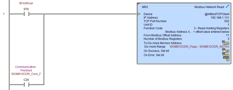
Upon the first scan of the PLC or when the communication has completed for the unit, we will start our communication. We will read the system flags, power up / safe, and watchdog timer.
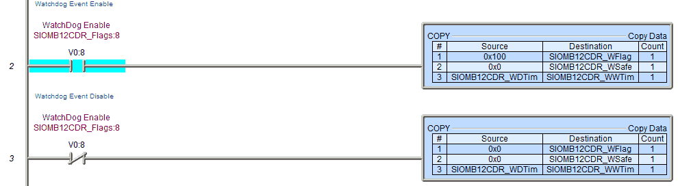
If the watchdog event is enabled then keep it enabled with the write data to the system flags. This will also clear the power-up and watchdog event flags.
Power Up / Safe Bits for Outputs
Upon power-up, the four outputs automatically are either on/off according to Bits 08, 09, 10, or 11 in V0. Upon the watchdog event happening the four outputs automatically are either on/off according to Bits 00, 01, 02, or 03.
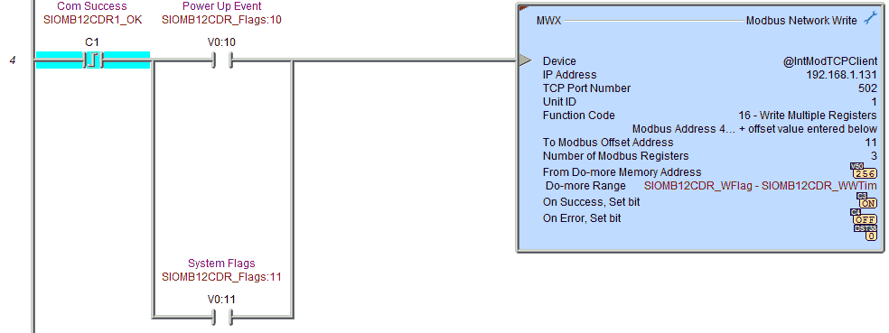
Write the following information:
System Flags – Clearing any watchdog or power-up event flags.
Power up / Safe – Status of outputs on the remote IO when the unit powers up or when the watchdog event happens.
WatchDog Timer – Set the watchdog timer.
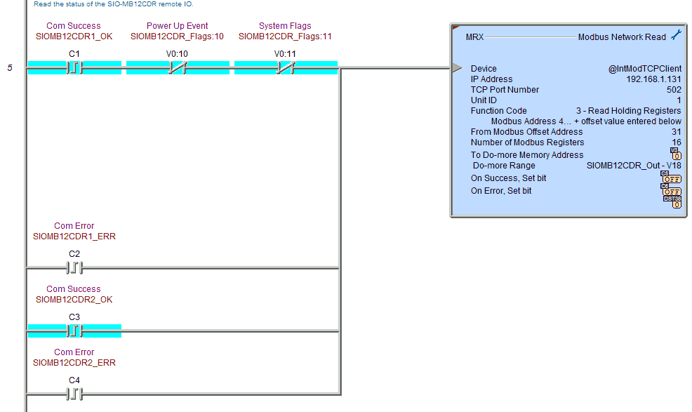
Read the status of the SIO-MB12CDR remote IO.
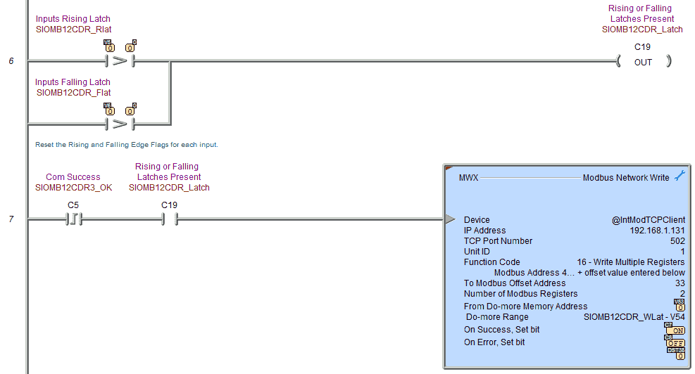
Determine if there are rising or falling edge inputs that need to be reset.
Reset the rising and falling edge flags for each input. This is done by writing a register that contains the value of 0 to each of the memory locations.
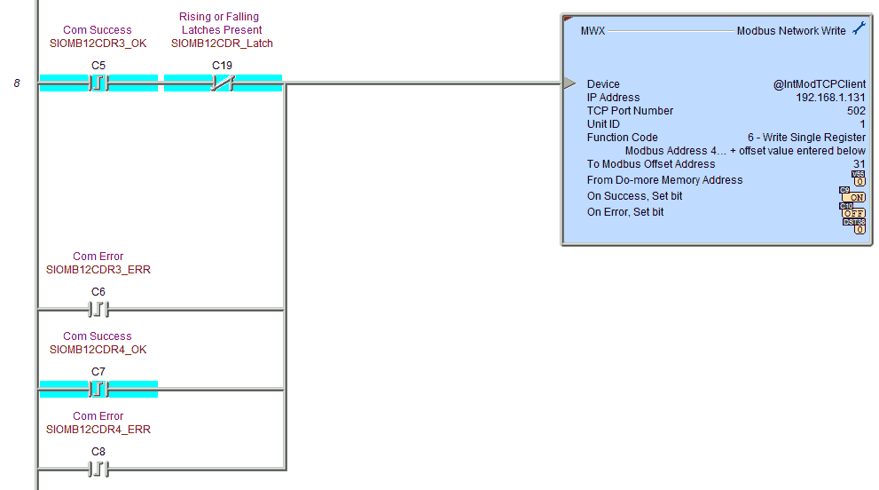
Write the outputs to the four relays to control the output relays.
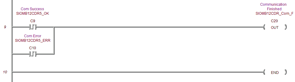
A flag is set to indicate that the update for the SIO-MB12CDR is now complete. Communication with this card can now start over again.
SIO-MB04ADS Program
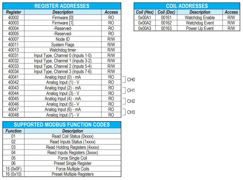
Here is the Modbus address chart for the remote IO unit.
We will map the following with our program:
System Flags:
V100:8 – WatchDog Event Enable
V100:9 – WatchDog Event
V100:10 – Power Up Event
Analog Input Types:
Disabled = 00h, Volt = 02h, mA = 03h
Input Type CH0 – V103 – #1 #0
Input Type CH1 – V104 – #3 #2
Input Type CH2 – V105 – #5 #4
Input Type CH3 – V106 – #7 #6
Analog Input Addresses:
Analog In #0 – V107
Analog In #1 – V108
Analog In #2 – V109
Analog In #3 – V110
Analog In #4 – V111
Analog In #5 – V112
Analog In #6 – V113
Analog In #7 – V114
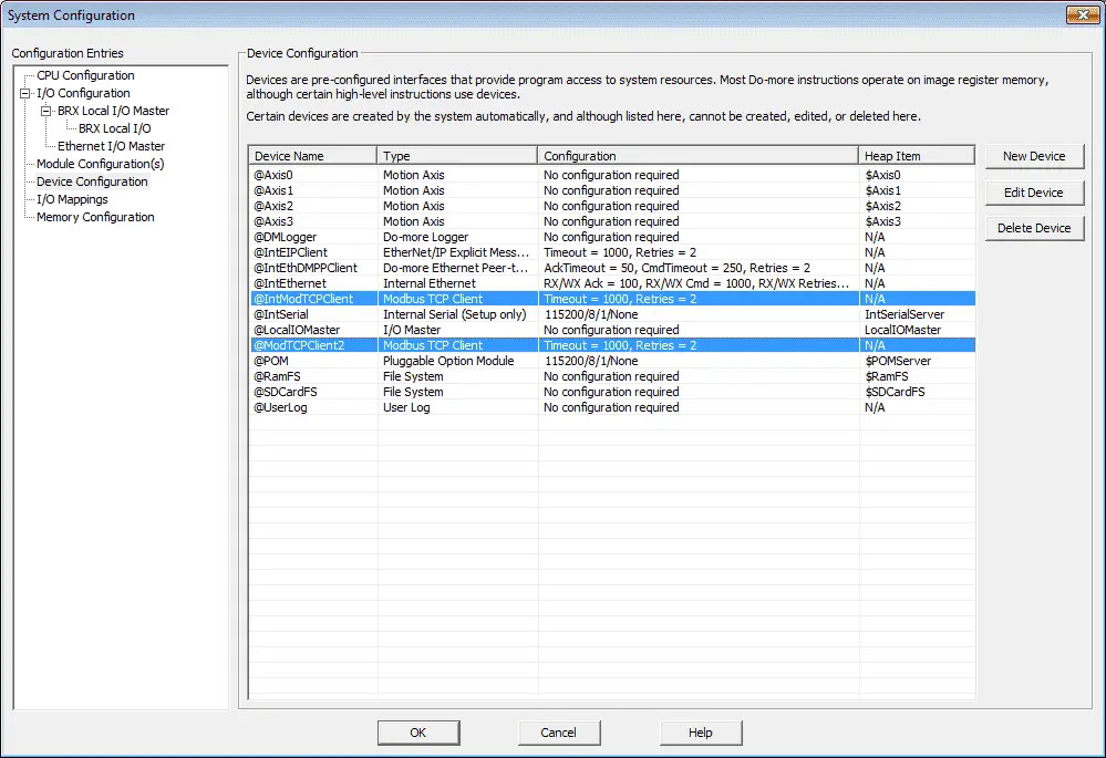
We will add another Modbus TCP client to our devices. Each of the remote input and output units will have their own device. Timing for communication will be done by the BRX CPU unit. Our new device will be called @ModTCPClient2.
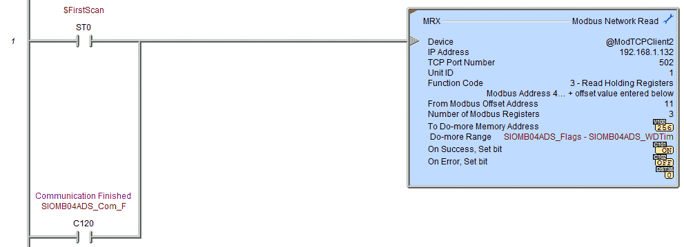
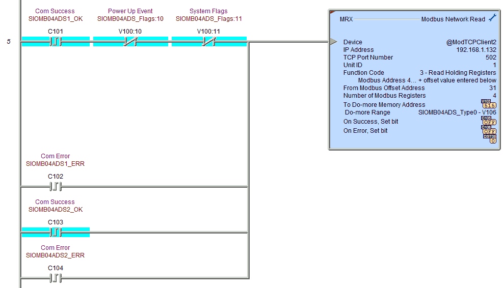
The first Modbus read will read the system flags and watchdog timer.
These registers will be placed in V100 and V102.
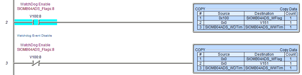
If the watchdog event is enabled then keep it enabled with the write data to the system flags. This will also clear the power-up and watchdog event flags.
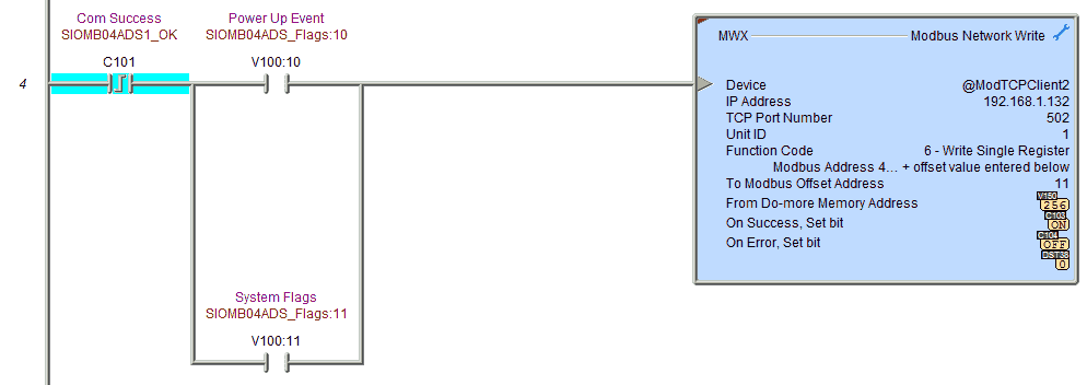
Write the following information:
System Flags – Clearing any watchdog or power-up event flags.
Read the input type of the SIO-MB04ADS remote IO.
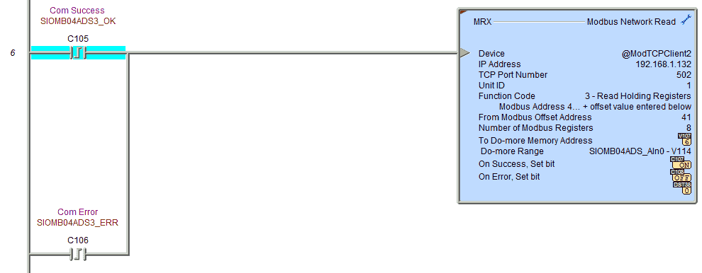
Read the status of the SIO-MB04ADS Analog Signals remote IO.
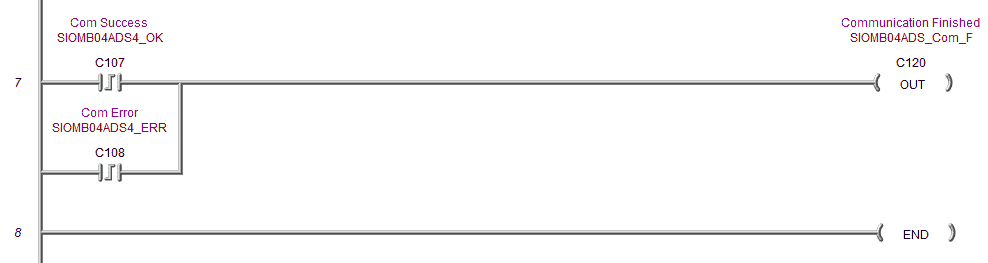
A flag is set to indicate that the update for the SIO-MB04ADS is now complete. This will trigger the communication to start again for the unit.
When we run the program, our current scan time can be monitored by using the main menu | PLC | System Information…
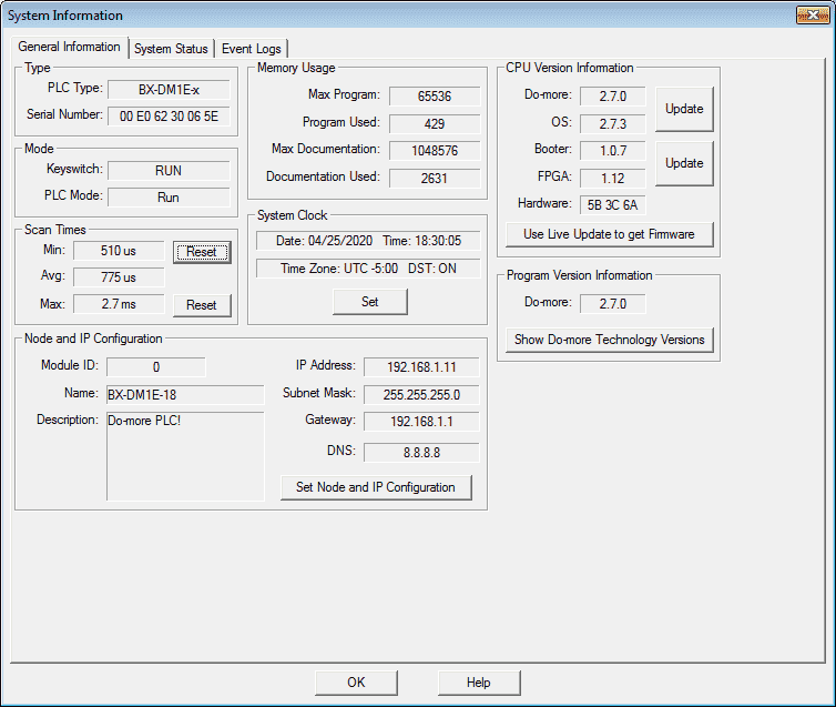
Under the heading scan times, you will see the minimum (Min), average (Avg), and maximum (Max) scan times for the BRX. You can reset the minimum and maximum times while you are connected online. Using this information, you can calculate roughly the throughput of your system. See the video below.
Watch the video below to see the Stride remote inputs and outputs in action on our BRX D0-More PLC.
Download the BRX D0-More PLC program here.
BRX Series PLC from Automation Direct – Power to deliver
Overview Link (Configure and purchase a system)
Manuals and Product Inserts (Installation and Setup Instruction)
Do-More Designer Software v2.7.3 (Free Download Link) – The software will contain all of the instruction sets and help files for the BRX Series PLC.
Stride Field Remote IO Modules Modbus TCP Ethernet Links:
Stride Remote Field IO Overview
Stride Field IO Modules Specifications
SIO-MB12CDR – Discrete Combination Module
SIO-MB12CDR User Manual
SIO-MB04ADS – Analog Input Module
SIO-MB04ADS User Manual
Modbus Learning Links:
Simply Modbus Frequently Asked Questions
Modbus TCP/IP Overview – Real-Time Automation
All You Need to Know About Modbus RTU – Video
Watch on YouTube: BRX Do-More PLC to Stride Field IO Modbus TCP
If you have any questions or need further information please contact me. Thank you, Garry
If you’re like most of my readers, you’re committed to learning about technology. Numbering systems used in PLC’s are not difficult to learn and understand. We will walk through the numbering systems used in PLCs. This includes Bits, Decimal, Hexadecimal, ASCII and Floating Point. To get this free article, subscribe to my free email newsletter.
 The ‘Robust Data Logging for Free’ eBook is also available as a free download. The link is included when you subscribe to ACC Automation.