The Click PLC retentive data memory registers are not included in the program file by default. All Click PLC CPUs are included. This option must be selected to include the C, CT, DS, DD, DH, DF, CTD, and TXT memory in the Click project file.
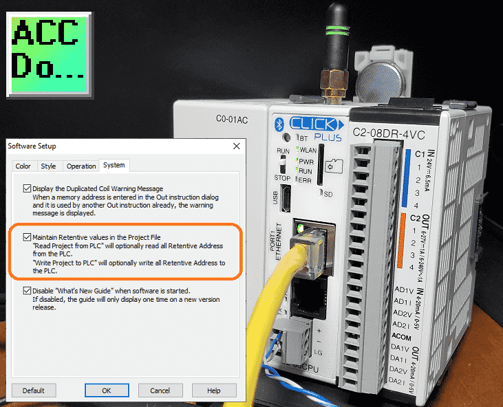 We will be enabling the option to include the retentive data memory in the Click program file from the Click programming software. We will also be installing a battery and programming an expiry date. This will indicate when the battery will need to be replaced. Let’s get started.
Our entire Click series can be found here. All of the previous information for the Click PLC can be applied to the Click PLUS.
Previously we looked at the following:
Software Installation – Video
Click Software Establish Communication – Video
MQTT Communication – Video
Data Logging – Video
Click Plus Real-Time Clock – Video
Serial Communication Timing – Video
The programming software and manuals can be downloaded from the Automation Direct website free of charge.
Watch the video below to see the storage of your retentive data in the program file of the Click PLC. Also, watch the installation and setting of an expiry date for the battery in the Click PLC using the Click programming software.
Maintain Retentive Values in the Project File
Normally, a Click project file only includes Initial Values for registers. We can change this to save the retentive values. In the Click Programming Software select software setup…
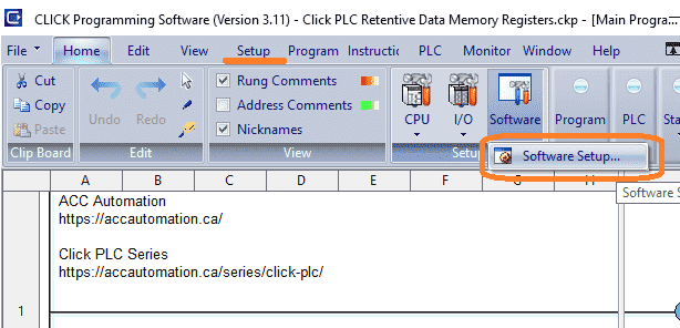 This is located under the main menu | Setup | Software Setup… You can also reach this by selecting Software Setup under the Software on the Home tab.
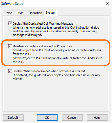 Selecting this option (Enabling) will prompt you during project transfers to either retrieve or write the values of the retentive registers. This includes C, CT, DS, DD, DH, DF, CTD, and TXT memory in all the Click PLC CPU units.
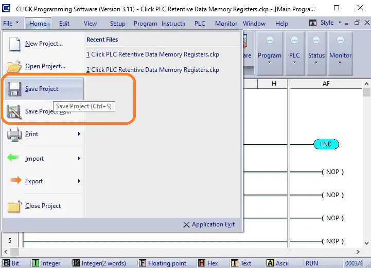 Saving the project file will prompt you to upload the current retentive values to the Click PLC project.
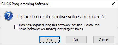 Select yes or no to upload the retentive memory. Cancel will stop saving the Click project file. You can select the don’t ask this software session. This will then ensure that the same answer will be used for subsequent project saves.
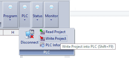 Writing the project file to the Click plc will prompt you to download the retentive values to the controller.
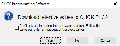 Selecting yes will write the values from the program file. This will save you manually initializing the memory values.
Watch the video below showing the setting of this option in the Click programming software.
Click PLC – SRAM Memory Retention
All Click and Click Plus PLC units make use of the data register to store values and conditions. These values as shown above can be stored in the project file on your computer as shown above.
The data is stored in the SRAM memory of the Click PLC. This volatile memory is backed up by a supercapacitor. The supercapacitor is a special type of capacitor that is designed to provide power to volatile memory like the SRAM when the power to the PLC is off.
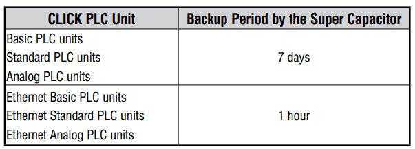 With power off to the Click PLC, the basic, standard and analog CPU units will store the data for 7 days using the supercapacitor. The Ethernet and Click PLUS CPU units will store the SRAM for 1 hour. Once the supercapacitor is discharged, all data in the SRAM is cleared.
To prevent the loss of SRAM memory during power down, the Click PLCs have a battery backup feature that will retain data in the SRAM for three years.
D0-MC-BAT (CR2032) is the battery for the Click PLUS PLC.
D2-BAT-1 (CR2354) is the battery for all the other Click PLCs.
Click PLC Battery Installation
To install or replace the D0-MC-BAT (CR 2032) battery:
1. Power up the CPU for at least 10 minutes to charge the CPU’s capacitor prior to removing the battery. This will retain function memories. It is recommended you backup data memory before replacing the battery. Plan to complete the battery replacement within 10 minutes of power off.
2. Power off the CPU.
3. Pull out the battery holder on the Click Plus CPU. (This may require a small screwdriver to push in the tab and lift it when the unit is mounted.)
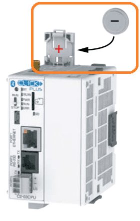 On all other Click CPU units, pull up the battery tab.
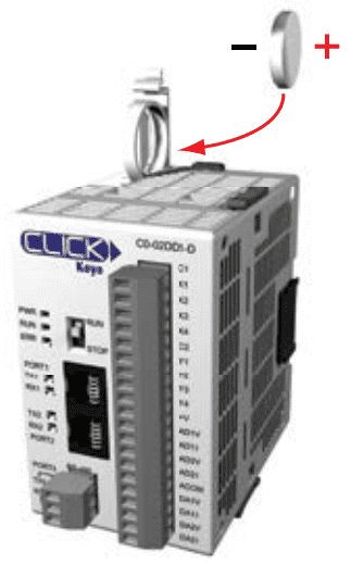 4. Put in a new battery, with the positive (+) polarity side facing the battery holder. This should snap into place. The (-) polarity side will face the battery holder on all other Click CPU units.
5. Insert the battery holder into the CPU and push it all the way in.
6. Power on the CPU.
7. Make a note of the date the battery was installed. (Battery life is about 3 years.) The battery backup is now available.
Watch the video below to see the installation of the CR2032 battery for the Click PLUS PLC.
Click PLC Programming Battery Replacement Date
The CLICK PLC has a feature that indicates the pre-scheduled battery replacement date has passed. This will activate an error light on the CPU.
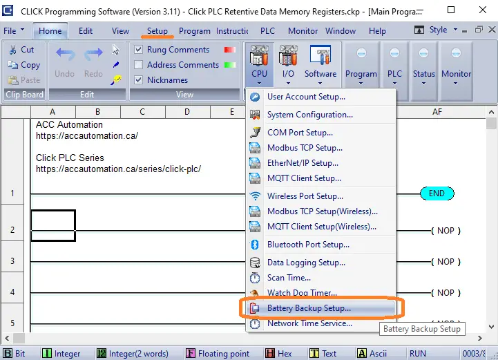 In the CLICK programming software, go to the pull-down menu: Setup | Battery backup Setup
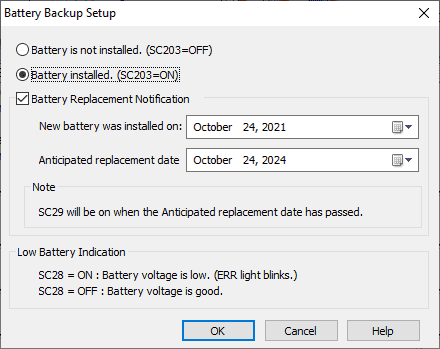 Select the Battery Installed option (SC203). This will enable the low battery (SC28) detection feature of the CPU.
Select the Battery Replacement Notification. Enter the dates depending on what battery you are installing. The Click batteries are good for at least three years.
Select OK and download the project file to the PLC. The ERR light on the CPU module (SC29) will start flickering when the Anticipated Date has passed.
Watch the video below to see the programming battery replacement date on the Click controller.
Click PLC Support Links
The Click PLC can be programmed using free Click programming software from Automation Direct. Here is a link to the software.
Version 3.00
Version 2.60
The entire Click PLC series prior to the Click PLUS release can be found here.
All previous posts and information are still valid with the Click PLC line-up.
YouTube Click Playlist
YouTube Click PLUS Playlist
Click and Click PLUS PLC Overview
Click and Click PLUS PLC Videos from Automation Direct
Modbus Learning Links:
Simply Modbus Frequently Asked Questions
Modbus TCP/IP Overview – Real-Time Automation
All You Need to Know About Modbus RTU – Video
Watch on YouTube: Click PLC Retentive Data Memory Registers
If you have any questions or need further information please contact me.
Thank you,
Garry
If you’re like most of my readers, you’re committed to learning about technology. Numbering systems used in PLCs are not difficult to learn and understand. We will walk through the numbering systems used in PLCs. This includes Bits, Decimal, Hexadecimal, ASCII, and Floating Point. To get this free article, subscribe to my free email newsletter.
Use the information to inform other people how numbering systems work. Sign up now. The ‘Robust Data Logging for Free’ eBook is also available as a free download. The link is included when you subscribe to ACC Automation.

