PLC programs scan cyclically. This means that it is repeated many times and in the same order. The primary sequence of a PLC scan is reading the inputs, executing the program, diagnostics, and communication, and updating the outputs.
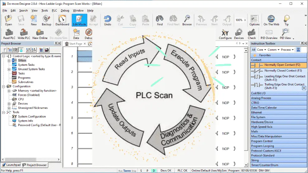 We will look at these scan items with particular attention to how the ladder logic program is executed. Let’s get started.
PLC Scan – Read Inputs
Reading the physical PLC inputs is the first thing the scan will do. A copy of the inputs is placed in the memory table.
Inputs can be push buttons, switches, proximity sensors, etc. They can be digital, on or off, or analog, giving you a range of voltage or current.
Inputs are usually optically isolated from the PLC CPU. This means they only share light, which will protect them in the industrial environment.
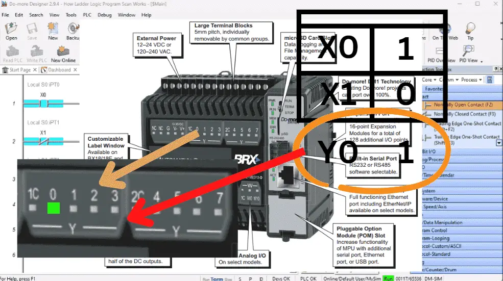
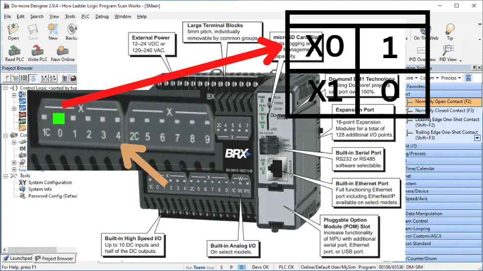 We are viewing the BRX Do-More PLC. This has the inputs built into the main unit with the CPU. (Central Processing Unit) As mentioned above, the physical inputs are copied into a memory table for each scan.
PLC Scan – Execute Program
The program will work with the memory table. All bits can be read or written in this table. This includes the inputs that have been read from the physical inputs.
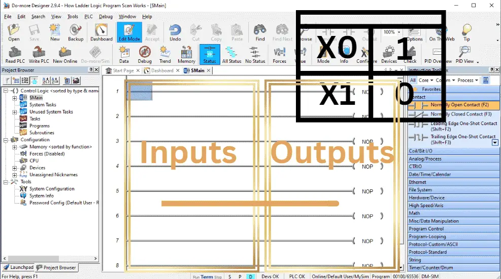 Ladder logic is similar to electrical wiring diagrams. Programs consist of rungs of ladder logic code. A rung will be made of inputs and outputs. Inputs are on the left side of the rung, and outputs are on the right side of the rung. If the input conditions are true, logic will flow from the right to the left. This will then activate or turn on the outputs for the rung. This will update the memory table.
Ladder logic is solved from left to right, top to bottom. The outputs from the previous rung are available for the next rung to use. This means that the memory table is updated as each rung of logic is solved, and the next rung will be able to use this modified information in the table. Let’s take a look at an example:
 We are using the Do-More Designer Software simulator. This is a free, fully functional PLC programming and simulation software package. See the download links below.
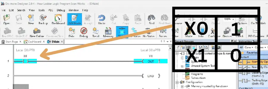
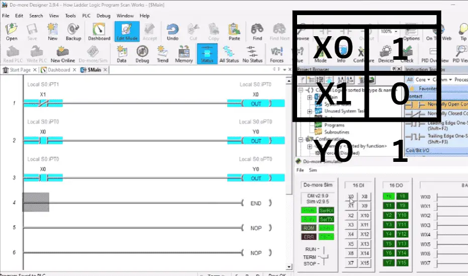
 This sample program has two rungs. When X0 is turned on, the scan will read the inputs and update the memory table. It will then execute the program. The first rung will look at the contact for X1 in the memory table. Since this is on, it will now look at the output and turn this output on in the memory table. The second rung is the END instruction. When the scan sees this, it will stop the execution of the program and move on to the next part of the scan. Remember that this scan happens several times per second.
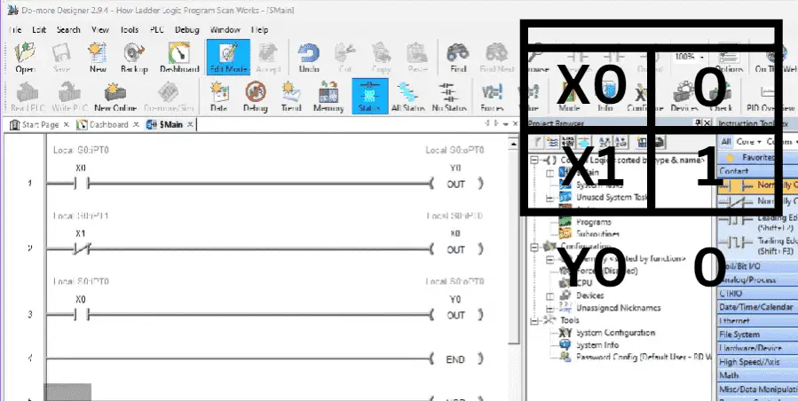 We have now added a couple more rungs to our existing program. This will demonstrate the execution of the program.
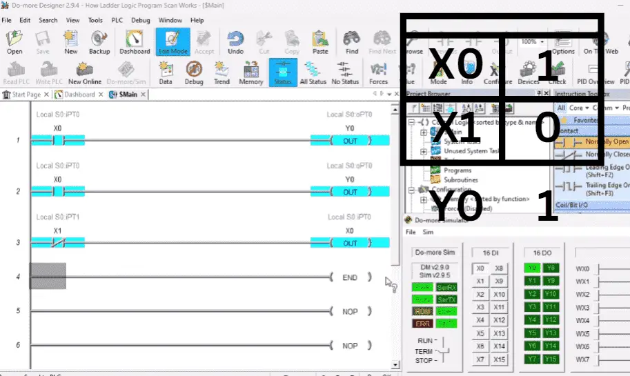
The normally closed X1 input will now set the output X0 in the memory table. The status of X0 will now control the output status of Y0 in the memory table. Rung 1 is repeated as Rung 3.
If X0 is off and X1 is on, then the first rung will turn Y0 off. The second rung will take the opposite of the memory table (normally closed), and being on it will set X0 off. Y0 will be off because X0 is off on the third rung.
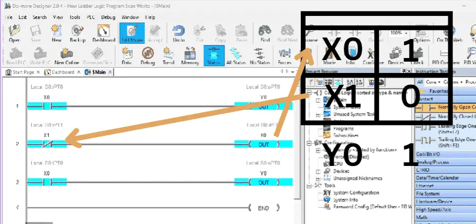 If X0 is off and X1 is off, then the first rung will turn Y0 off. The second rung will take the normally closed X1, which is on, and set X0 to on. Y0 will be on because X0 is on for the third rung.
The sequence of program execution is essential to understand when programming PLC logic.
PLC Scan – Diagnostics and Communication
Features and the number of processors will depend on the model of the programmable controller that you are using. Timing of these processors with the main logic scan will determine if the PLC uses a synchronous or asynchronous input and output (I/O) scan. The PLC scan’s diagnostics and communication part are where other PLC processors can share their data with the memory table.
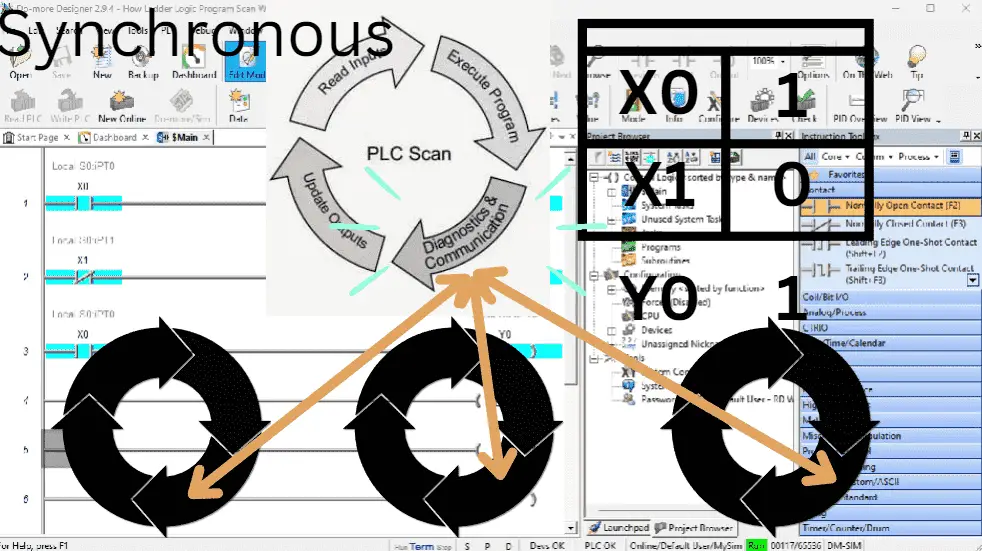 It is synchronous if the diagnostics and communication only happen once in a PLC scan.
 This is asynchronous if this occurs at any time, and the memory table gets updated anytime or multiple times during the scan.
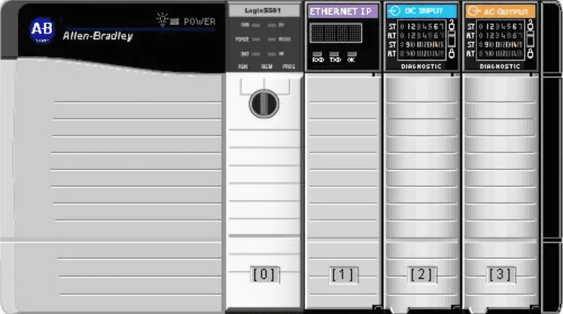 Controllers like Allen Bradley CompactLogix using the RSLogix 5000 software use asynchronous I/O scan. This means that updating the I/O memory table will happen whenever possible.
In an asynchronous I/O scan, you typically only use the actual I/O reference once in your program. Most programmers of these systems will transfer the I/O to internal memory first. They will then use the internal memory in the program code. This will now act like a synchronous, predictable scan PLC.
Please refer to your PLC manual to determine the scanning method of your controller.
PLC Scan – Update Outputs
PLC physical outputs are updated once per scan. The memory table for the outputs is copied to the physical outputs. This will activate your lights, relays, etc.
 The outputs are optically isolated from the PLC CPU unit, just like the inputs. The CPU will be protected by optical isolation. If the output is destroyed by faulty wiring or surges, usually, it is only that output or card that will need to be replaced.
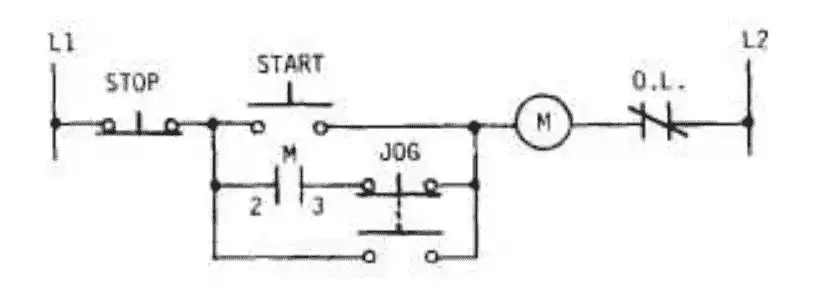
A physically wired relay is a Break-Before-Make device. When triggered, the relay will break (open) the first set of contacts before engaging (closing) the new connections. There is a time delay from breaking one circuit and engaging the next.
 Traditionally wired circuits, when replaced by a PLC, may have to change the logic slightly.
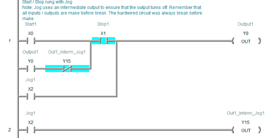 Here is an example of a start-stop jog circuit. Think of the outputs or inputs in the PLC as Make-Before-Break. Since the PLC scan will update the outputs once per scan, the normally open and normally closed contact will happen simultaneously.
The post “How to Make a Start Stop Jog Circuit” demonstrates this make-before-break.
The last rung of ladder logic code will always overwrite anything previous in the memory table. An excellent method of troubleshooting logical errors in the PLC would be to move the rung with the output to the end of the scan. This would allow the rung to be the last to update the memory table before writing to the physical outputs.
 In our example, you will see that X0 will not control the output. We will move rung 1 to the bottom of the program. The errors will show that we have duplicate outputs. We will leave this as is because we are only demonstrating. X0 will still not control the output.
 We will move the rung with output X0 now to the bottom of the program. Our program now works due to the scan of the programmable logic controller.
Watch the video below to see the operation of the PLC Scan.
Free learning and training series for PLCs.
BRX Do-More
Productivity Series
P1000
P2000
Click / Click PLUS (Koyo)
Omron CP1H Series
Horner XL4 Series
EasyPLC Software Suite – 3D training package
Purchase your copy of this learning package for less than USD 75 for a single computer install or less than USD 100 to allow different computers.
Receive 10% off the investment by typing in ACC in the comment section when you order. http://www.nirtec.com/index.php/purchase-price/
Learn PLC programming the easy way. Invest in yourself today.
C-More EA9 Series of HMI
(Webserver, FTP, Data Logging, Free Remote Apps, etc.)
Node-Red is a free IoT software hub that can communicate MQTT and many standard industrial protocols. This series will help you communicate to the PLC, create an HMI on any electronic device, log data to a database, and view the information on a spreadsheet for analysis.
Node-RED IoT enabling software
Watch on YouTube: How Ladder Logic Program Scan Works
If you have any questions or need further information, please contact me.
Thank you,
Garry
If you’re like most of my readers, you’re committed to learning about technology. Numbering systems used in PLCs are not challenging to learn and understand. We will walk through the numbering systems used in PLCs. This includes Bits, decimals, Hexadecimal, ASCII, and Floating points.
To get this free article, subscribe to my free email newsletter.
Use the information to inform other people how numbering systems work. Sign up now.

The ‘Robust Data Logging for Free’ eBook is also available for free download. The link is included when you subscribe to ACC Automation.